
How To Create A 3d Corkscrew Using 3d Modelling Software

Made by simran-khuntia / 3D Printing / Artificial intelligence / Augmented Reality / Home Automation / Retro Tech
About the project
In this tutorial blog, we will learn the stepwise process to design a 3D corkscrew in SelfCAD
Project info
Difficulty: Easy
Platforms: Amazon Alexa, Android, Bosch, Google, Microsoft
Estimated time: 2 hours
License: Apache License 2.0 (Apache-2.0)
Items used in this project


Story
3D designing is becoming well known in many fields. Previously, it was just an expertise being mastered by experts in structural designing, mechanical designing, and different callings. Be that as it may, with the appearance of simple-to-utilise programs like SelfCAD, everybody, no matter what their experience, can get everything rolling with the product no sweat. What makes SelfCAD extraordinary is that as well as being not difficult to utilise, it's additionally adequately strong to be utilised to make complex designs. Its point of interaction is uncommonly regular, and exceptionally expected for self-understanding. It has a wide combination of tools, including express devices expected to manage the model for genuine 3D printing.
In this article, we will design a 3D corkscrew in SelfCAD. We will completely go through the cycles and clarification of every single step.
You can also go through our website and check our other such articles for example, how to design a 3D screwdriver!
We should get moving!
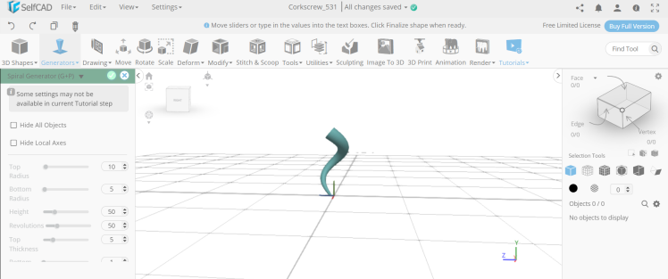
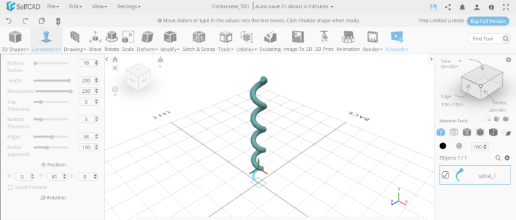
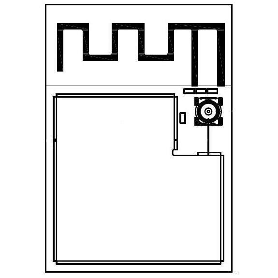
Step1: Insert two spiral generators of different dimensions
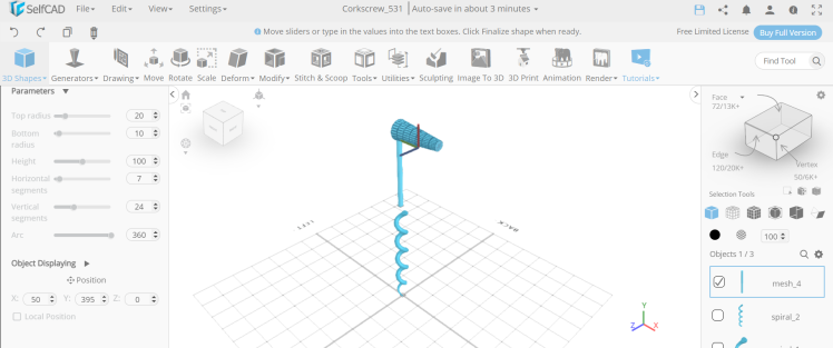
First of all, from the 3D shapes category insert a spiral generator. Set top radius to 10, bottom radius to 5, bottom thickness to 1, and edge to 34. Then insert another spiral generator and set its top radius to 10, bottom radius to 10, height to 200, revolutions to 200 to 1, edges to 34 and position y to 41.
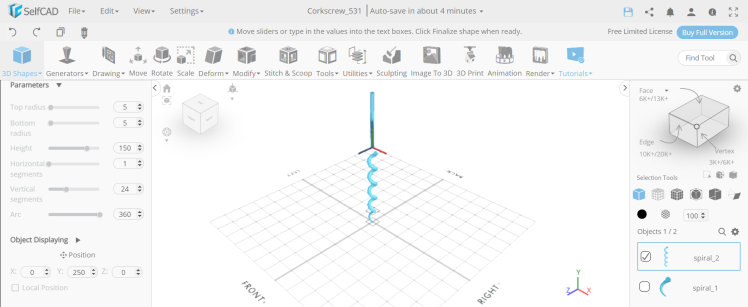
Step2: Insert two different cylinders
Next, insert a cylinder and set its top radius to 5, bottom radius to 5, height to 150, and position y to 250. Then insert a cylinder and set its top radius to 20, bottom radius to 20, horizontal segments to 7, position x to 50, and position y to 395, and rotation z to 90.
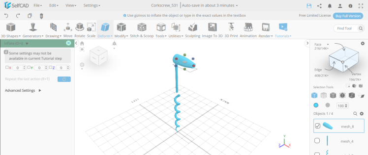
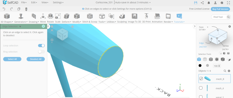
Step3: Inflate the object and select the edges
Now, from the deform category select the inflate tool. Set symmetry to true, y to 3, and z to 3. Then opt for edge selection, set loop selection to true and select the smaller circular edge of the cylinder.
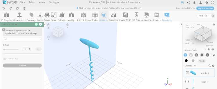
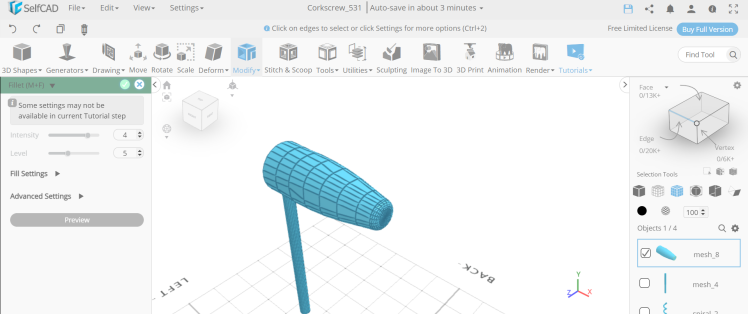
Step4: Fillet the edges and select the object
Next, from the modify category select the fillet tool. Set intensity to 4 and level to 5. Then from the utilities category choose the mirror option. Set create copy to true, direction to left.
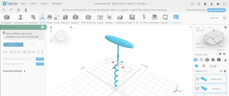
Step5: Position all the objects correctly and make them a union
Now, select all the objects except the spiral one. Select the move tool and set y to 233, x to 10 and z to -2. Then select all the objects, go to stitch and scoop and make them a union.

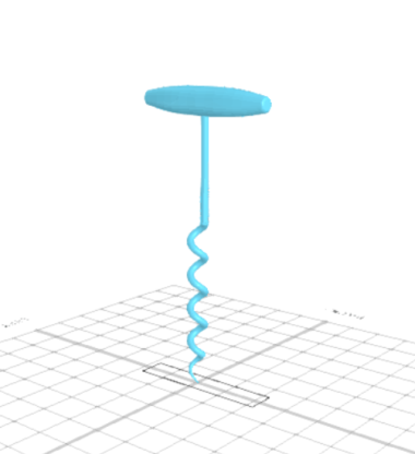
Conclusion: Hence, we have created a 3D corkscrew in SelfCAD
The means are smooth and can be effortlessly executed. As we probably are aware, SelfCAD simplifies the interaction, so it will be fascinating to plan more 3D designs like this. Moreover, it's a genuinely sensible web-based plan with an extensive number of clients. SelfCAD is currently being used in schools, homes, and associations all over the world.
Credits


Leave your feedback...