
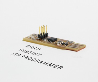
How To Build A Usbtiny Isp Programmer

Made by suhail_jr / Communication / Sensors
About the project
The best way to use CNC milling machines to build your PCB. PCB milling machines give you good quality PCB and it takes less time, less resource and cheapest way to produce PCB prototypes!So, let's build a USBtiny ISP programmer by utilizing a CNC milling machine!Without further do, let's get started!
Items used in this project
Hardware components

View all
Hand tools and fabrication machines
Story
Step 1: You Don't Want to Be Rich!
Really! you don't want to purchase a PCB milling machine. Most of us don't have the budget to buy an expensive machine like this. I don't even have one.
So, how I get access to a machine?Simply, I just go to a fablab, makerspace or a hackerspace in my locality!In my case, I just go to a fablab and use the machine for a cheap price. So, find a place like fablab or a makerspace in your locality. For me, the price is 48¢/hour for using PCB milling machine. The price may vary in your locality.So, like I said you don't want to be rich!
Step 2: Bill of Materials
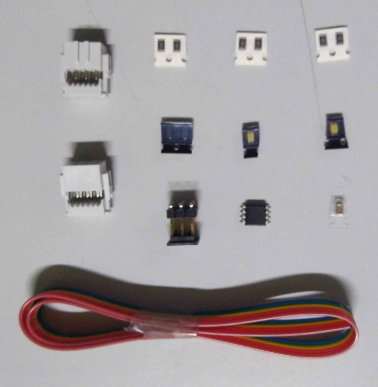
Components list
- 1 x Attiny 45/85 microcontroller (SOIC package)
- 2 x 499 Ohms
- 2 x 49 Ohms
- 2 x 1K
- 2 x 3.3 Zener diode
- 1 x 0.1mf capacitor
- 1 x Blue led
- 1 x Green led
- 1 x 2x3 Male header pins (smd)
- 1 x 20cm 6wire Ribbon cable
- 2 x 2x3 Female Header IDC Ribbon Cable Transition Connector
- 1x 4cm x 8cm FR4 Copper Clad
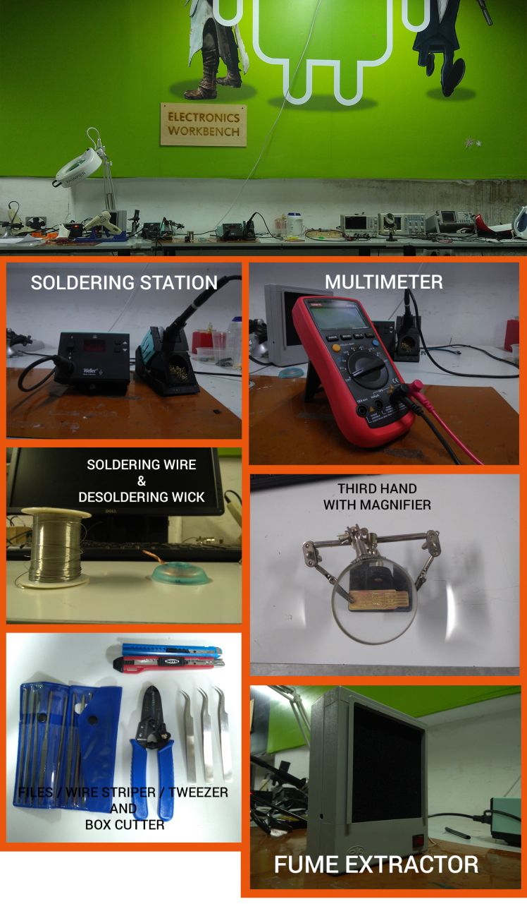
Tools requirements
- Soldering station or soldering iron (Micro tip)
- Soldering Lead wire
- Tweezer (microtip)
- Desoldering Wick
- Third-hand tool
- Multimeter
- Wire Stripper
- Fume Extractor (Optional)
Machines Requirement
- Modela MDX20 (Any PCB milling machine do the job, but the job control software will change)
Download the resources for this project!
Step 3: What Is a PCB Milling Machine?
PCB milling machine is a CNC (Computer Numerical Control) machine that used to fabricate PCB prototypes. PCB milling machines are mill away the copper parts of the copper clad to make out traces and pads of the PCB. The PCB milling machine comes with a three-axis mechanical movement (X, Y, Z). Each axis is controlled by a stepper motor for precisional movements. These axis movements are controlled by a computer program by giving G-code commands. Gcode is widely using Numerical control programming languages, most of the machines are using g-code to control the axis of the machines. A tool head (usually a milling bit) is connected to these axes will mill out the PCBs.
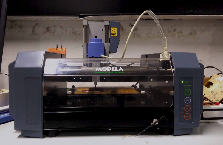
:- The machine am using is a MODELA MDX20 CNC milling machine.
Modela MDX 20 PCB Milling Machine
Modela MDX20 is PCB milling machine. Modela MDX20 is usually used to fabricate PCBs but we can also make moldings, etchings etc... Modela can mill on different materials like Plywood, Wax, Acrylic, Differents PCB materials like Fr1 Fr4 etc... The modela is lightweight and comes with small in size. We can place it on even a small desktop. The bed (milling surface) is attached to Y-axis and the tool head is attached to X and Z. That means the movement of bed is controlled by Y-axis and movement of tool head is controlled by X-axis and the tool head is controlled by Z-axis. Modela have its own computer program. But I am using a Linux program called FABModules. FABmodules communicate with Modela to control the cutting and milling process. Fab Modules never set X, Y, Z axis automatically, we need to set them manually.
Step 4: Get Started With Modela MDX20
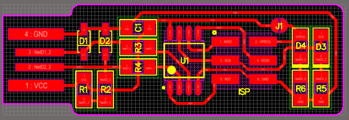
If I want to mill my PCB, in this case, a FabISP programmer. First I need a PCB design layout and a PCB outline layout. The PCB milling is a two-stage process. In the first stage, I need to mill out the traces and pads of the PCB and in the second stage, I need to cut out the PCB outline. Using fab modules we can convert .png PCB design layout to G-code. The G-code contains the coordination and tool path to mill the PCB. The .png image should be in black and white color combination. The milling machine will mill out the white portions using the tool head and the black portions will leaves as it is. So, the traces and pads should be in black color format.
General Specification
- Workspace : 203.2 x 152.4 mm
- Z-axis stroke: 60.5mm
- Spindle speed: 6500RPM
Milling Bits To use
- Milling Bit: 1/64 inch (0.4 mm) bit
- Cutting Bit: 1/32 inch (0.8 mm) bit
Step 5: What Is ISP (IN - System - Programmer)?
In System Programmer (ISP) also known as In-Circuit Serial Programmer (ICSP) is a microcontroller programmer. The ISP will read the instructions and commands from the computer USB and send to the Microcontroller through the serial peripheral interface (SPI). Simply ISP devices allow us to communicate with the microcontroller using SPI lines. SPI is the way of communication in the microcontroller. Every connected peripherals and interface communicate with microcontrollers through SPI. As an electronic enthusiast, the first thing comes to my mind when say about ISP is MISO, MOSI SCK. These three pins are the important pins.
Simply, ISP is used to burn programs to the microcontroller and also used to communicate with your microcontroller!
Step 6: USBTiny ISP : Schematics and PCB Layout
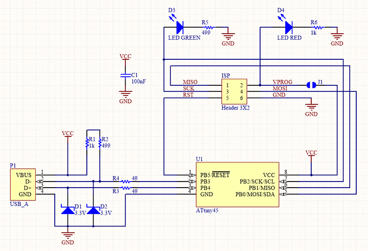
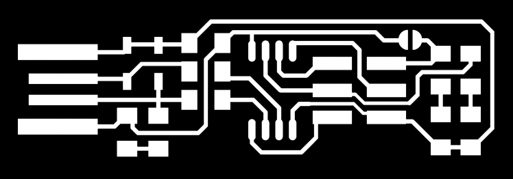

USBTiny ISP
USBTiny ISP is a simple open-source USB AVR programmer and SPI interface. It is low cost, easy to make, works great with avrdude, is AVRStudio-compatible and tested under Windows, Linux and MacOS X. Perfect for students and beginners, or as a backup programmer.
All the components are used in this projects SMD Components. The brain of the USBTinyISP is an Attiny45 microcontroller.
ATtiny 45 Microcontroller
The microcontroller that is using in USBTinyISP is Attiny 45. Attiny45 is a High performance and low power 8- bit AVR microcontroller running on RISC Architecture by Atmel (microchip acquired Atmel recently). Attiny 45 comes in an 8 pin package. Attiny 45 has 6 I/O pins, Three of them are ADC pins (10 bit ADC) and other two are Digital pins supporting PWM. It comes with a 4KM flash memory, 256 In-System Programmable EEPROM and 256B SRAM. Operating voltage around 1.8V to 5.5v 300mA. Attiny 45 support Universal Serial Interface. Both SMD version and THT versions are available in the market. Attiny 85 is a higher version of Attiny 45, They are almost the same. The only difference is in the Flash memory, Attiny 45 have 4KB flash and Attiny 85 have 8KB flash. We can choose either Attiny 45 or Attiny 85, Not a big deal but Attiny 45 is more enough to make FabTinyISP. See the official documentation from here.
Step 7: Setup the Machine
Now let us Build the PCB using the PCB milling machine. I included the Trace layout and Cut layout in the zip file, you can download the zip file from below.
Prerequestment: Please download and install the Fabmodules from this linkFabmodules only supported in Linux machines, I am using Ubuntu!
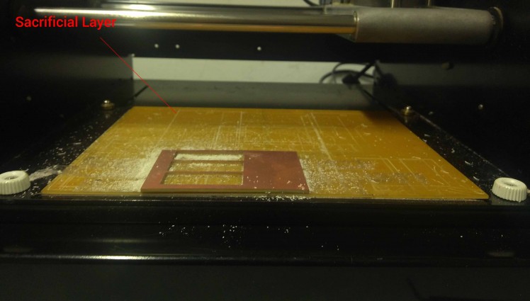
Step1: Sacrificial Layer
First of all, the work plate of the PCB milling machine (AKA milling bed) is a metal plate. It is sturdy and well builds. But in some case, it may damage while cutting in over depth by mistake. So, I place a sacrificial layer on top of the milling bed (a copper-clad placed on top of milling bed to avoid touching bits in the metal plate).
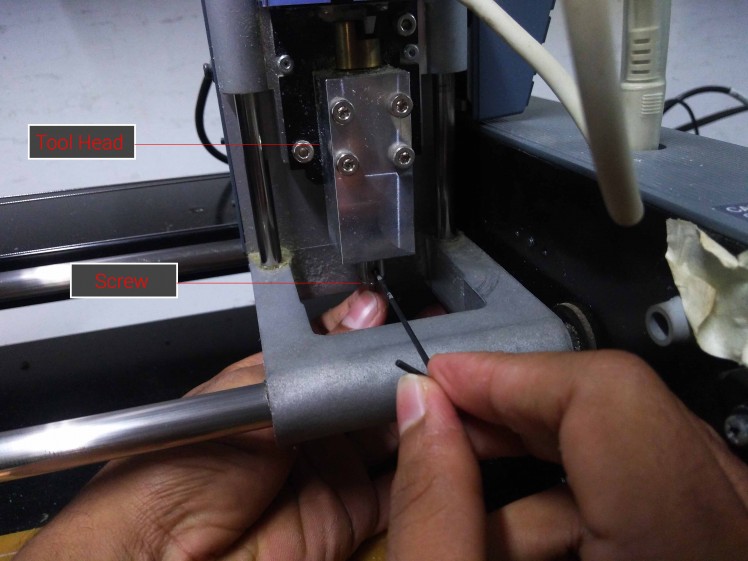
Step 2: Fix the 1/62 milling bit in the tool head
After placing the sacrificial layer, Now I need to fix the milling bit (usually used a 1/62 milling bit) in the tool head. I already explained the two-stage process of milling PCBs. For milling the traces and pads of the PCB, use a 1/64 milling bit and place it on the tool head using the Allen key. While changing the bits, always give an extra care for the bits. The bit's tip is so thin, It has more chances to break the bit while slip from our hands even it is a small fall. to overcome this situation, I placed a small piece of foam under the tool head to protect from accidental falls.
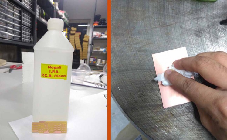
Step 3: Clean the copper clad
I am using a FR1 copper clad for this project. The FR-1 are heat resistant and more durable. But copper clads will oxidize quickly. Coppers are fingerprint magnets. So before using a copper clad even it is a new one, I recommend you to clean the PCB with a PCB cleaner or acetone before and after milling the PCB. I used a PCB cleaner to clean the PCB.
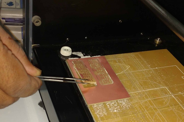
Step 4: Fix the Copper clad on the milling pad
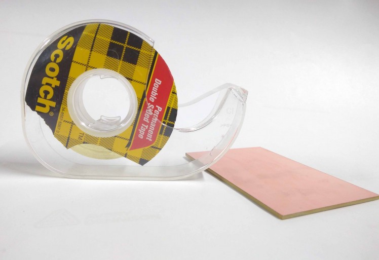
After cleaning the copper clad, place the copper clad on the top of the milling bed. I placed the copper clad on the milling pad with the help of a double sided sticky tape. The double-sided sticky tapes are so easy to remove and they are available for a cheap price. I stick the double sided tape on the top of the sacrificial layer. Then placed the copper clad on the top of the sticky tape.
Step 8: Setup Fab Modules and Milling Process
Step 1: Power the machine and Load FabModules
powered on the machine and then open the Fab module software in a Linux system (I'm using Ubuntu) by typing the below command in the Linux terminal.
fab
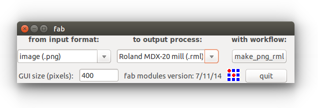
Then a new window will pop up. Select image(.png) as input file format and output format as Roland MDX-20 mill(rml). After that, click the Make_png_rml button.
Step 2: Load the PCB design Image
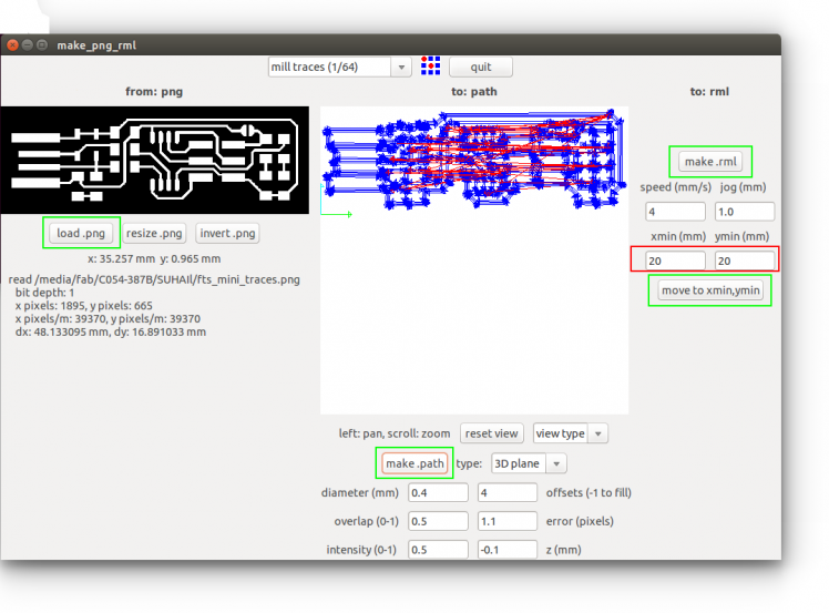
In the top of the new window select the bit that you are going to use. then load your .png format by clink Load.png button. Then click on Make.path button to generate the path to for mill. Now click the Make.rml to generate the instructions and commands for the machine. A new Send it Button will appear on the top make the Make.rml button. Do not click on the button right now.
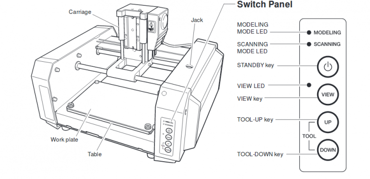
Step 3: Set X, Y & Z Axes
We are not done yet. Now press the View button on the Modela MDX20 control panel. make sure the bit is well tight. press once more the view button to get back to the default position. Now set the X, Y positions by entering the measurements (depends on your board position) in desired text boxes. I recommend you to note down the X & Y positions somewhere. If something went wrong and you need to start from first, You should need the exact X&Y positions to continue your milling process else it will mess up.
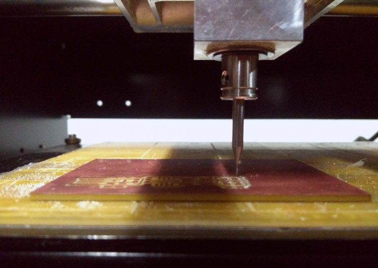
Bring down the tool head by pressing Down button. Stop when the Tool head reaches near to the copper clad. Then lose the tool head screw and bring down the bit a little bit down until it touches the copper layer of the copper clad. Then tighten the screw back again and bring back the tool head to the home position by pressing View button. Now we all set. Close the safety Lid of the Modela and click Send it button. The modela will start the milling process.
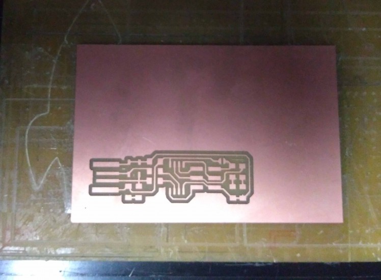
It shall take a minimum of 10 to 13 minute to mill the traces and pads. After finishing the milling I got a good result.
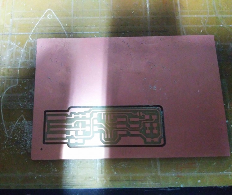
Step 4: Cutting the Outline layout
After finishing the Trace milling, Cut out the PCB outline layout(simply shape of the PCB). The process is almost the same. For cutting the layout, Change the 1/64 bit to 1/32 bit in tool head. Then load the cutting layout .png file to fab modules and select the cutting bit(1/32) in the tools menu. Then continue the same procedures that idid earlier. Take out the completed PCB from the bed.
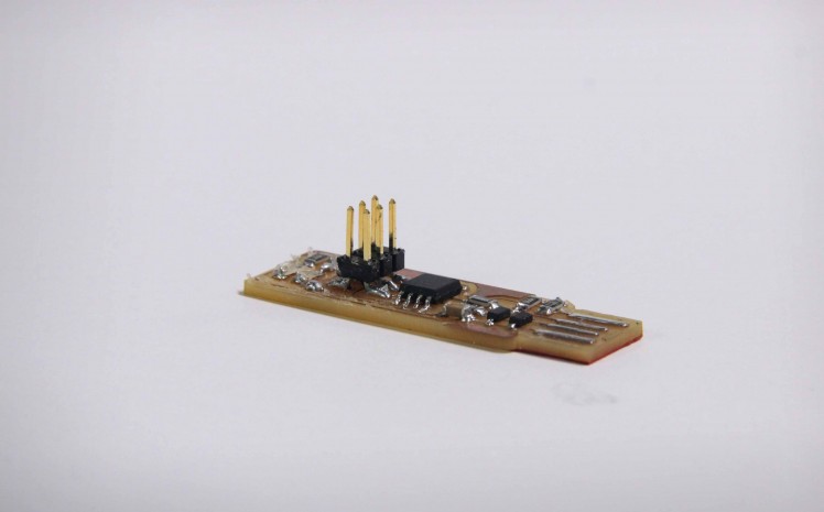
Step 9: Finished PCB
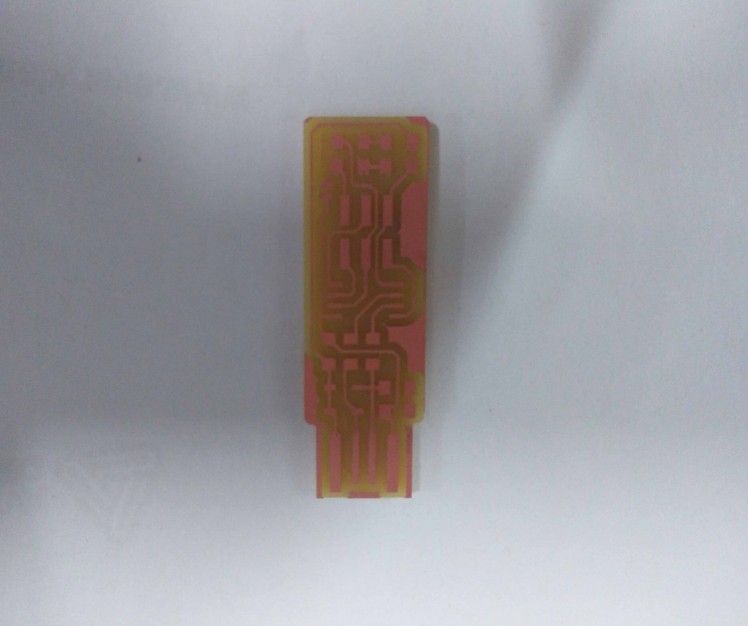
Here is the PCB after the milling process!
Step 10: Soldering the Components on PCB
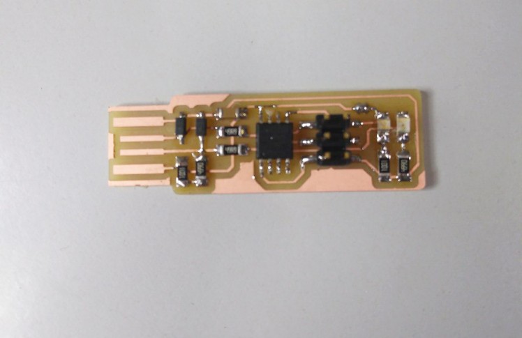
Now I have a finished PCB. all I need to do is solder the components on the PCB. For me, it is a fun and easy task.
When it comes to soldering, Through-hole components are so easy to solder when comparing with SMD components. SMD components are small in their footprints. it is a little bit difficult to solder for beginners. There are a lot of chances to make mistakes like cold solders misplacements of components and the most common thing or make bridges in between traces and pads. But everyone has their own soldering tips and tricks, that they were learned from their own experiences. this will make this task fun and easy. So take your time to solder the components!
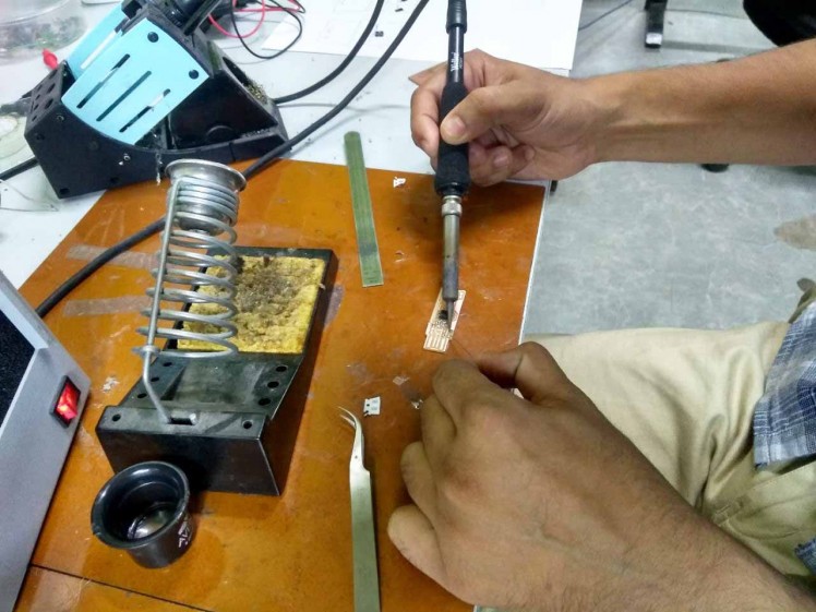
Here How I Do Soldering!
I usually solder Microcontrollers and Other ICs first. Then I solder small components like resistors and capacitors etc...
At last through-hole components, wires and header pins. To solder my USBTinyISP, I follow the same steps. To solder SMDs easily, First, I heat up the soldering iron to a 350°C. Then add some solder flux on pads. Then heat up the pad which I want to solder the components, then I add a little amount of solder to a single pad of the component pad. Using tweezers, pluck the component and place on the pad and heat up the pad for 2-4 second. After that, solder the remaining pads. If you make bridges between pins and traces or gives a lot of solder to a component, used the solder wick ribbon to remove the unwanted solder. I continue the same steps until the PCB fully soldered without any problem. If something went wrong, first I carefully check all traces and components having breaks or bridges using a magnifier and multimeter. If I found, then I rectify it!
Step 11: Making the ISP Cable
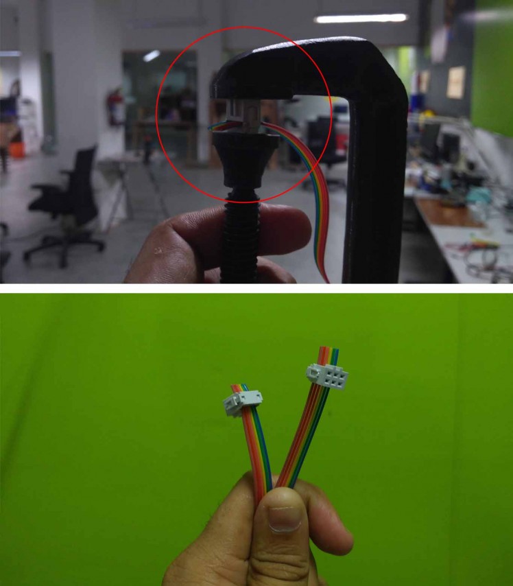
To connect the microcontroller or another ISP programmer to flash the firmware. we need a six line ribon ribon wire with two 2x3 female wire conector. I used a 4/3 feet 6 channel ribbon wire and carefully connected the female header on both sides. To do nicely I used a G clamp. see the picture.
Step 12: Flashing Firmware
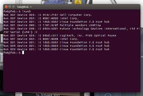
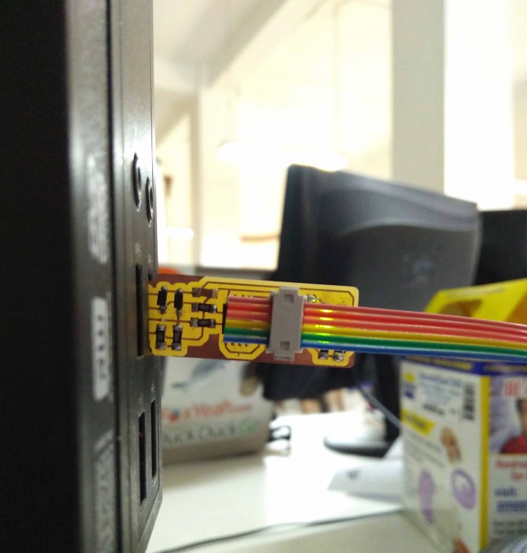
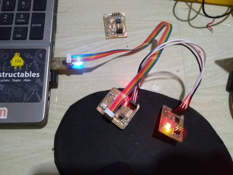
Now we can flash the firmware to our ISP. To do that we need another ISP programmer. I used another USBTinyISP, But you can use an Arduino as ISP to do this task. Connect both the ISPs using the ISP connector that we previously made. Then connect USBinyISP(The one we are using for programming) to the computer. Make sure the ISP is detected in your system by typing the below command in the Linux terminal.
lsusb
Step 1: Install AVR GCC tool chain
First of all, we need to install the tool chain. To do that, open a Linux terminal and type.
sudo apt-get install avrdude gcc-avr avr-libc make
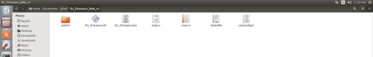
Step 2: Download and unzip the firmware
Now download and unzip the firmware files. You can download it from here. After downloading the zip file, extract into a good location that you can find easily (to avoid unnecessary confusions).
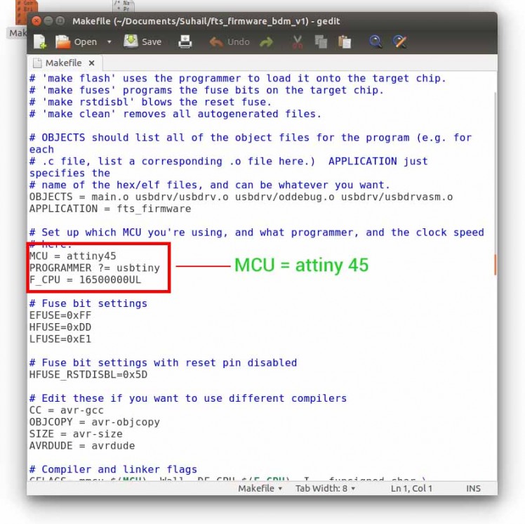
Step 3: Make file
Before burning the firmware. we need to ensure the makefile is configured for the Attiny microcontrollers. To do this open the Makefile in any text editor. then confirm MCU = Attiny45. See the image below.
Step 4: Flash the firmware
Now we can flash the firmware to our ISP. To do that we need another ISP programmer, as I said earlier. I used a FabTinyISP, that I made earlier. But you can use any ISP or use an Arduino as ISP programmer. Connect both the ISPs using ISP connector that I previously made. Then connect FabTinyISP (the one I using to program my ISP) to the computer. Make sure the Isp is detected in your system by typing the below command in the Linux terminal.
lsusb
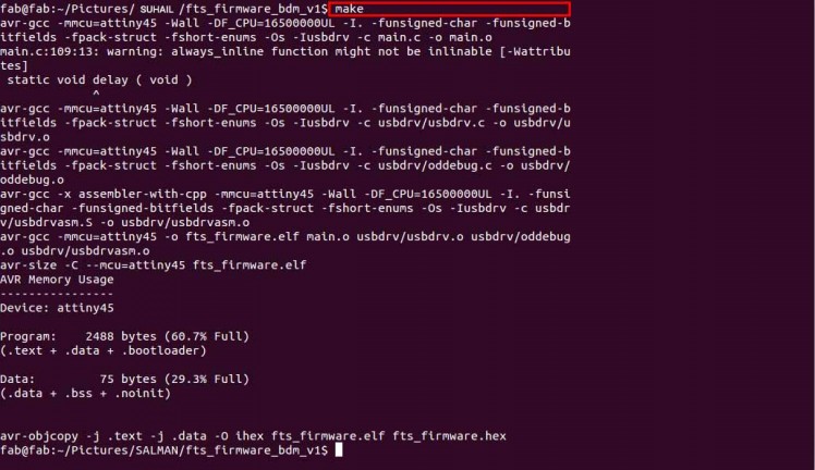
Now we are ready to flash. Open the terminal in the folder path of the firmware located and type "make" to make the .hex file. This will generate a .hex file that we need to burn into the Attiny 45.
Type the below command in Linux terminal to flash the firmware to the microcontroller.
make flash
Step 5: Enabling Fusebit
That's it we are done flashing the firmware. But we need to activate the fuse. Just type inmake fuse
the terminal to activate internal fuse.
Now we need to either remove the jumper or disable the reset pin. Removing jumper connection is not mandatory, we can disable the reset pin. It is up to you. I choose to disable the reset pin.
Please note:- If you disable the reset pin, then the Reset pin will be disconnected internally. Means you can't program it anymore after disabling the reset pin.If you want to disable the reset pin, then type make the below command in terminal.
rstdisbl
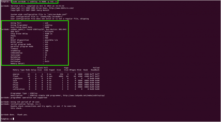
You will get a success message. After uploading the firmware successfully i need to check the USBTinyISP is working correctly, to do that you need to enter a command in terminal
sudo avrdude -c usbtiny -b9600 -p t45 -v
After entering the command, will get the return feedback in the terminal window.
Step 13: We Are Done
Now you can remove both devices from the computer and use the USBtiny that built right now to programme you microcontrollers from now on. I am using this ISP to flash my Arduino sketches.
Credits
suhail_jr
I am a maker and hardware enthusiast from India. I provide workshops on IoT and opensource hardware. I am the organizer of several hardware communities in India. Hardware community Kerala, and Fablab Kerala are the most remarkable. Now working as Technology innovation fellow @ Kerala startup mission and Fablab Kerala
Related products


Leave your feedback...