

Hiking Tracker

Made by electrouser805 / Environmental Sensing
About the project
Tracks compass heading, altitude, temperature, pressure, humidity, time, travel distance and GPS location during a hike.
Project info
Difficulty: Easy
Platforms: Adafruit, Arduino, Intel
Estimated time: 1 hour
License: GNU Lesser General Public License version 3 or later (LGPL3+)
Items used in this project
Hardware components


View all

Story
What is Hiking Tracker ?
Hiking Tracker is a device to sense the change in surrounding environment of a hiker during hiking.
The idea is to observe the change in temperature, pressure, humidity, altitude, location, direction etc. It gives some interesting insight of hiking.
On the mountains where it is cold, dry, low density air compared to lower lands, many people find it hard to breath. Some experience dry skin irritation. This device lets people interested in hiking to know their limits. There is also the fun of going to high altitude places. Being able to know the altitude is a fun thing !
Not only the mountains but also exploring swamps, deserts, forests - with each has its unique environmental profile, being able to monitor the environment on the go is a better way to understand the nature.
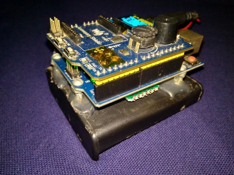 Stacked layers
Video Demonstration
Sensors dataStep 1 : Hardware, which for what ?
There are lots of sensing going around with this project
The accessory shield comes with some I2C devices on board :
- LM 75B temperature sensor for sensing ambient temperature
- ADXL345 3-axis accelerometer for sensing tilt and gravity
- DS3231 high-precision RTC for sensing time
- HMC5883 3-axis magnetic sensor for sensing compass heading
- AM2320 humidity sensor for sensing % RH of air
- BMP180 pressure sensor for sensing atmospheric pressure and altitude
- MTK3339 GPS sensor for sensing location and walked distance
On the Arduino Uno:
- 3.9k + 22k voltage divider for sensing 4 AA battery voltage
- 1306 OLED for viewing data
- Buzzer for alarm beep
- RGB LED is not needed for this project
- XBee interface is not used but Arduino D2, D3, D9, D10 can be brought out from this interface for other projects, D2 is connected to reset, which allows resetting the Arduino from code !
- 5-way joystick is not used
- 101 pot is not used
Step 2 : Modifying & Connecting the Hardware
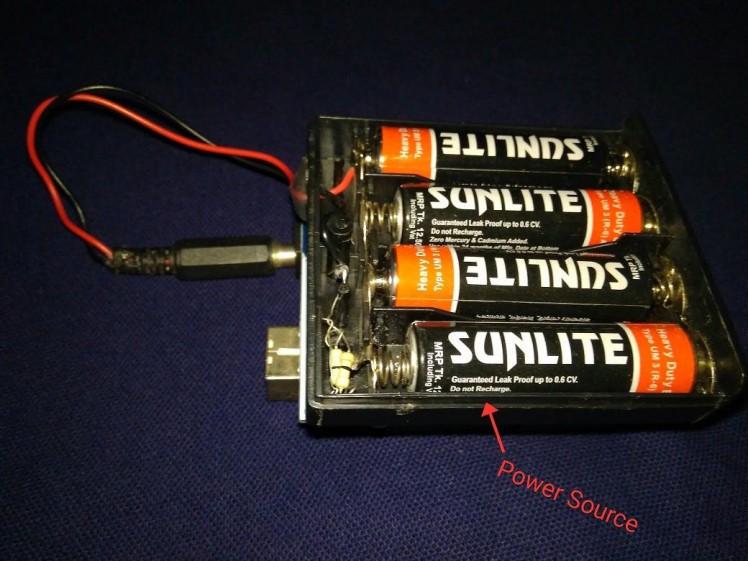
Few modifications are made on the Arduino Uno. It is mounted on a 4 AA Battery holder with screw standoffs and hot glue.
; ;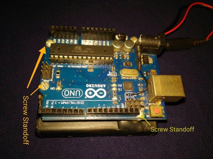 1 / 2 • Arduino on top of Battery Holder
4 AA and CR1220 (for RTC) are installed on battery holders.
; ; 1 / 2 • 4 AA with holder
There is a space between the battery holder and Arduino Uno board where the pressure, humidity, magnetic and GPS sensor can be placed.
; ;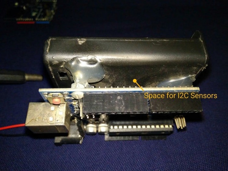 1 / 2 • Space for sensor
I2C sensors are soldered together on a piece of pref board and placed in this space
; ;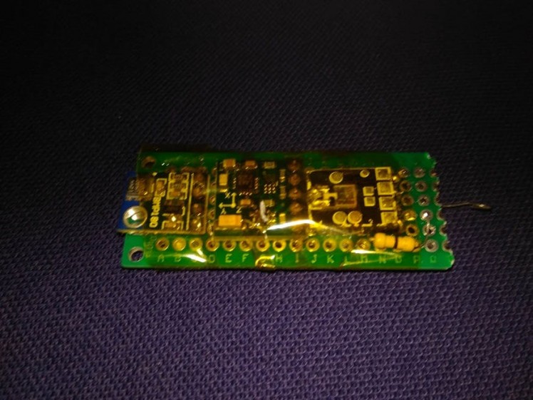 1 / 2 • Pressure, Humidity, Magnetic sensors are tied together on a I2C lane
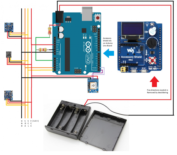
These sensors are connected to Arduino Uno from the bottom side :
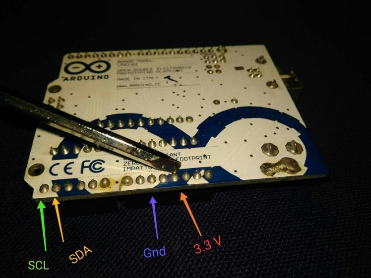 I2C connection and power for the sensors (will be soldered)
A voltage divider is added to measure battery voltage of 4 AA batteries.
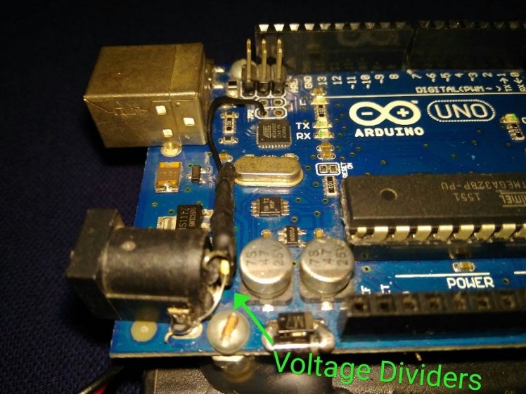 voltage divider soldered on power barrel connector
The AA battery pack voltage sense line goes to ADC A1 :
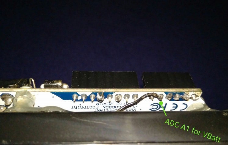 Voltage divider to ADC A1
The joystick of the shield is mapped to the ACD pin A1 through pin A5. That is why the joy stick is desoldered and removed.
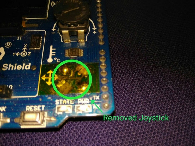 5 way Joystick removed
By connecting some pad on the Accessory Shield (for schematic see reference) with solder bridge D2 (for soft reset), D3, D9, D10 pins of Arduino are made available on Xbee interface.
; ;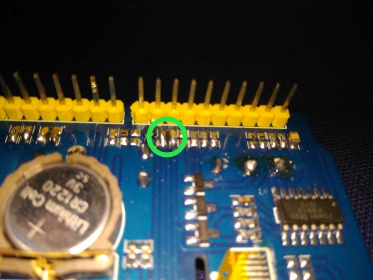 1 / 2 • D9, D10 pin breakout solder bridges
The components stack like this:
 Putting it all together !
- Top Layer : Accessory Shield on Arduino
- Middle Layer: Other Sensors and GPS will go between Uno and Battery Case
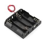
- Bottom Layer: 4 AA Battery Holder with batteries
And the connections look like this:
 Internonnections
Step 3 : Programming the Device
Arduino IDEBuild 1.8.5 is used to program the device. First all the following libraries are included or downloaded using the library manager.
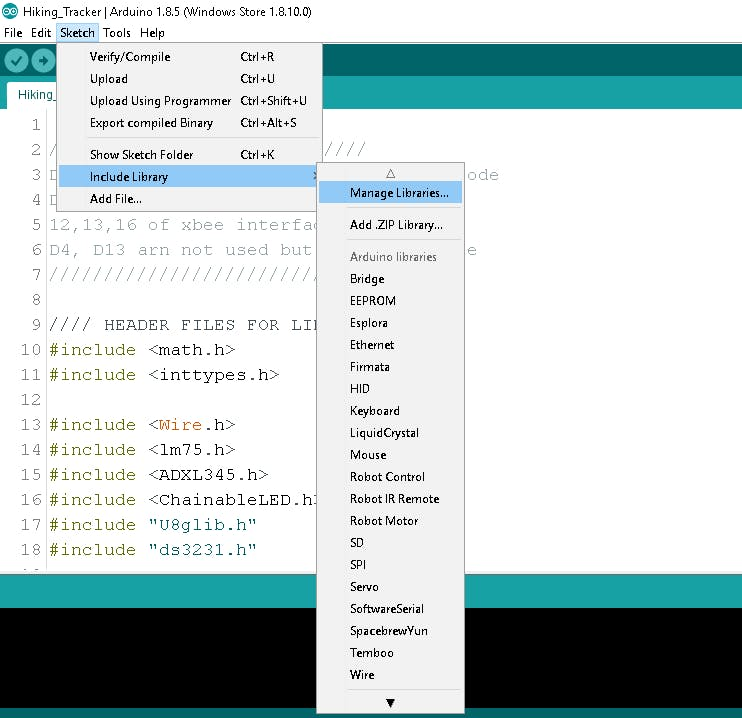 Adding Libraries
By typing the name of the sensor on the search box of library manager, appropriate libraries will appear.
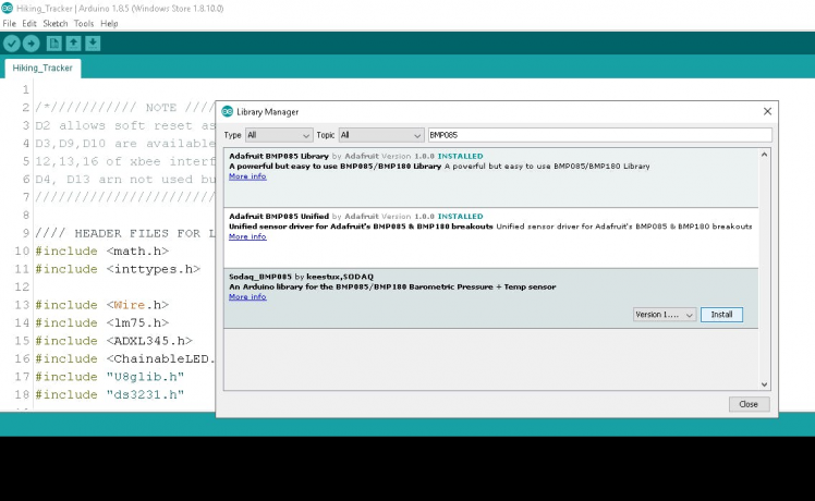 Click install to add new library
Some of the Accessory Shield libraries (see reference) are added through zip.file option
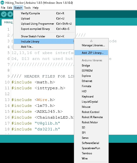 Adding library manually with library zip
After adding necessary libraries, example codes for each sensor is reviewed to find out the APIs for associated sensors.
Next, all the library headers are included in one empty Arduino sketch.
List of Header files
math.h,inttypes.h,Wire.h,lm75.h,ADXL345.h,ChainableLED.h,U8glib.h,ds3231.h,Adafruit_Sensor.h,Adafruit_AM2320.h,Adafruit_BMP085_U.h,Adafruit_HMC5883_U.h,Adafruit_GPS.h
After multiple edit, compile and debug ( including loose connection, where I discovered the BMP180 works without Vcc due to leakage power for I2C pins maybe ) and upload - finally the code was ready.
The Caveats
- Altitude calculation is based on Air Pressure Drop, applicable only during normal weather condition.
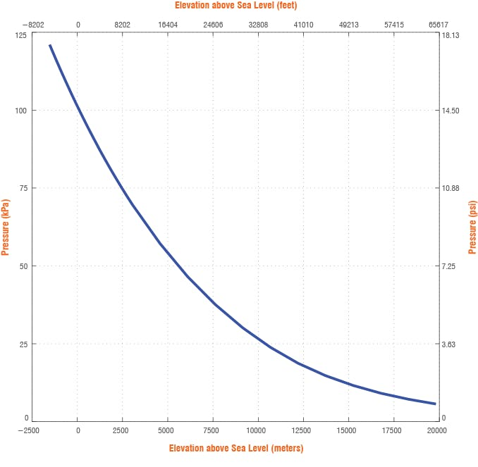 Air Pressure vs Altitude
- Compass code is not tilt compensated in software, device must be held in a level plane. There is a fixed compass circle, in which there is another variable radius circle. When the device is tilted, the inner circle will increase. When it is in a leveled position ( i.e. both x and y component of acceleromere is almost 0 ) the inner circle will reduce to a point. This is when the compass heading is more accurate.
- Compass pointer declination angle depends on location and variation of Earth's magnetic field. Which may get affected by Solar storm. If declination angle is not included, compass heading will be off by few degrees.
Find declination for your area : http://www.magnetic-declination.com
- Compass heading is prone to nearby magnetic objects, like presence of strong magnetic minerals on mountains.
- Device minimum operating voltage is about 4.5 volts. This is when AA batteries should be replaced.
- Time and Date is programmed from code, If time is needed to change the coin cell battery must be unplugged and plugged. A fresh program upload with new time in the code will change the time.
- During development GPS module was not available. Hence, demo coordinates are placed in Lat-Long. If someone wishes to replicate this project, it is required to include GPS library and associated codes.
- XY plane of Accelerometer and Magnetometer are subject to placement on PCB. Code is required to be adjustment accordingly.
- Accelerometer reading accuracy is prone to vibration. It is advised to use the device on stand still condition.
Scope of Improvement
Improvements can be done from the firmware side for few more features:
- Periodic logging of parameters on EEPROM
- Buzzer alarm beep on reaching altitude/location milestone
- Drink water reminder
- Take a break reminder
- Low battery alarm
- Low temperature, humidity alert
- Compass software calibration for tilt compensation (lots of trigonometry stuff)
- Auto fetch declination using GPS and IoT connectivity through Gateway app
As for the hardware part of improvement :
- User input switches for setting time, declination etc.
- Custom 3D case for the device
- Using Rechargeable LiPo Battery
- Single board compact PCB design for more portability
Conclusion
Traveling & Hiking is cool, when you can check the change in surrounding environment, it makes things more interesting. Specially, checking the altitude, humidity, pressure and temperature changes within hours while hiking. This device lets you know at what height you feel altitude sickness, what humidity level makes your skin dry - stuffs like that. Although there is room for improvement in both circuit layout and code to deal with the caveats, it's still cool to have a gadget like this while going into the wilderness!
External Resources
https://www.waveshare.com/wiki/Accessory_Shield
Recommended Hardware for a better version of this Project
Schematics, diagrams and documents
Code
Credits
Related products


Leave your feedback...