

Helium Air Quality Sensor

Made by Jade7272 / Environmental Sensing
About the project
A Helium-based air quality sensor and solar setup.
Project info
Difficulty: Difficult
Platforms: Adafruit, Maxim Integrated, Raspberry Pi, SparkFun
Estimated time: 7 days
Items used in this project
Hardware components


Story
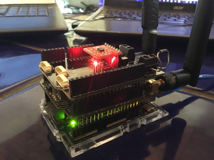 What a beautiful sight
As environmental concerns and awareness increase, I decided to build and deploy an array of wireless, self-contained, weather-resistant, solar-powered air quality sensors, also known as WSPAQS. The sensor array measures CO2 levels and VOCs. (What's a VOC, you ask? See below as it's rather long.) It also has a voltage/current sensor to keep track of the solar charge.
We will be using an Arduino Uno, a Raspberry Pi 3, Helium Starter Kit, my board, an Adafruit 6 volt solar panel a 24 VAC/VDC portable power converter to USB board (design files attached), and a hacked portable battery pack to build an awesome sensor setup that will transmit the data to Librato.
 Real-time monitoring anywhere in the world
Step 1: Hack apart a battery pack and test it for compatibility witth your system
Step 2: Add solar panel and put it in the sun
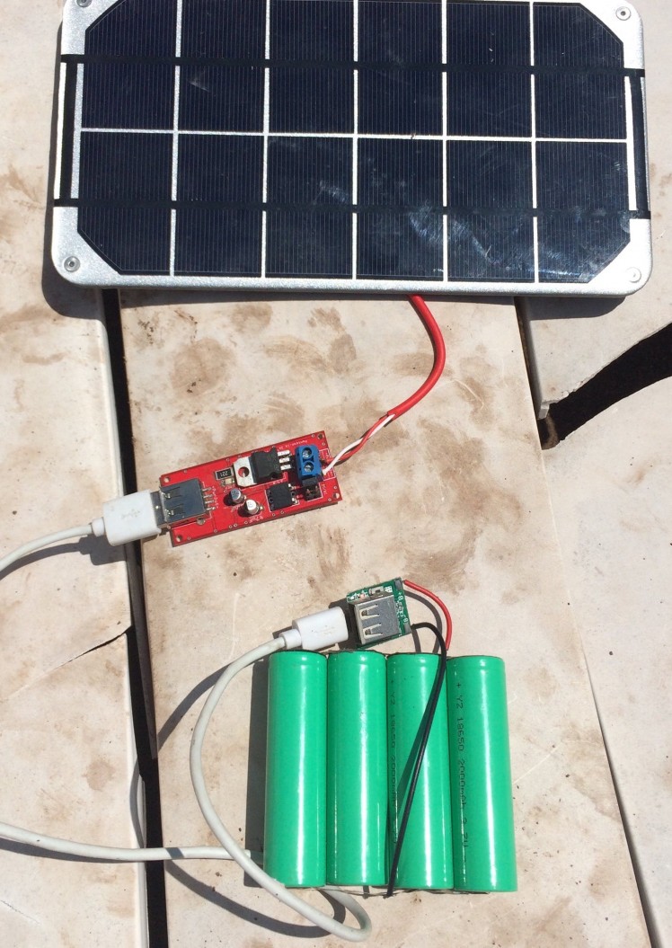 Solar Panel and charger setup working
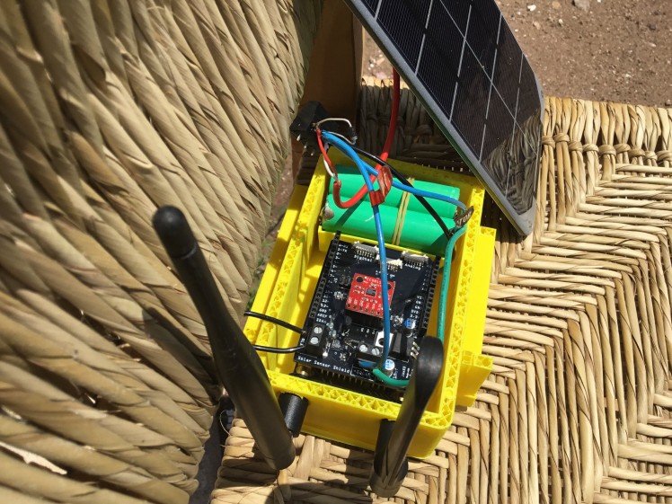
Step 3: Modify the battery pack to power the sensor array and so it fits into the box a bit easier
I cut the pack in 2 pieces and re-soldered them together, then soldered 2 wires to the power output for powering the Helium and Arduino sensor board array....the WSPAQS.
 Ground side of re-solder
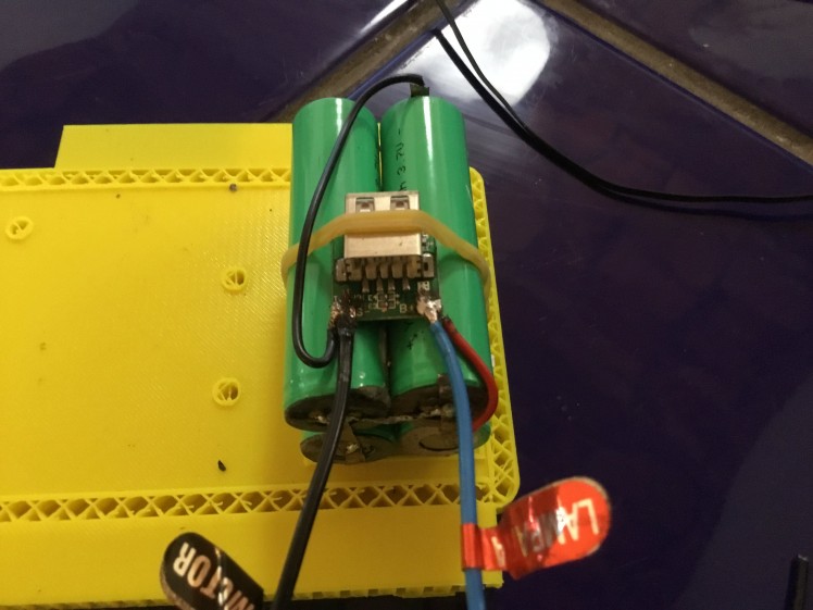 Positive side with charge module on top
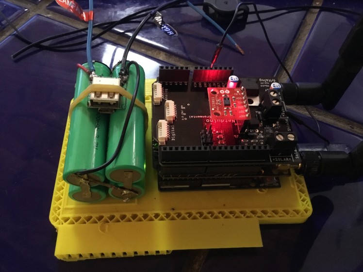 Mock-up placement
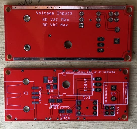
Step 4: Your board
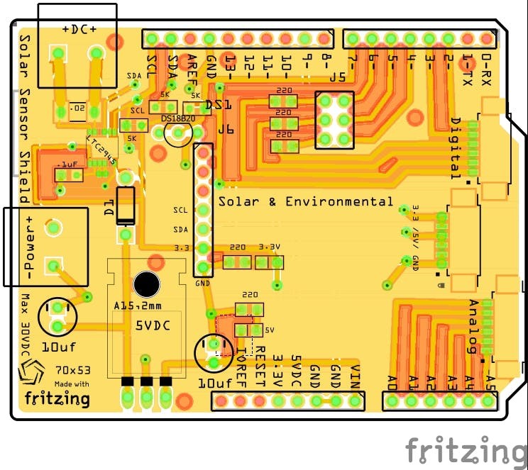 The Fritzing drawing of the board
These boards can be ordered through PCBWay: http://pcbway.com. There is a Gerber file in the tutorial that you can upload and pay $5.00. You'll then have it in 7 days.
Step 5: Solder your board starting with the SMD parts first
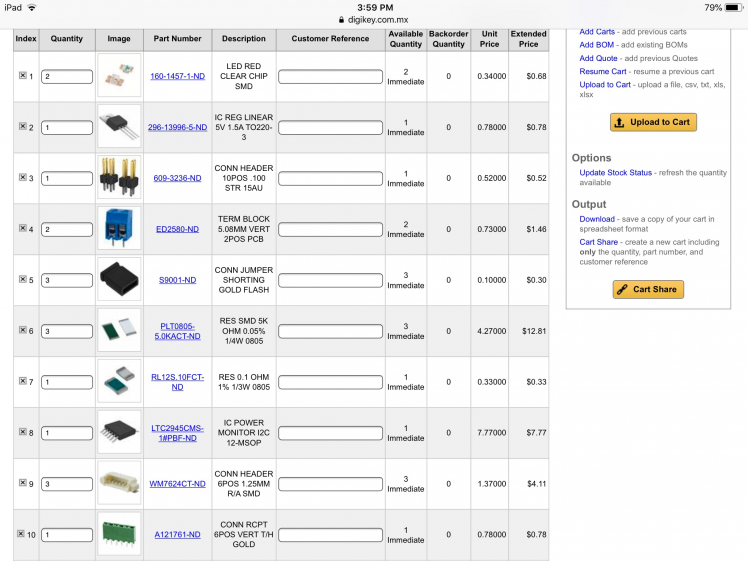
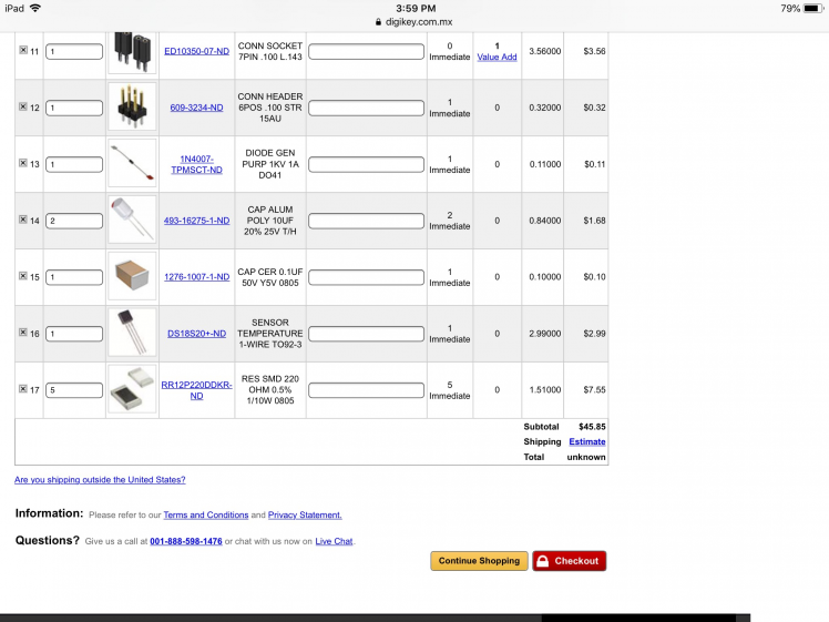
Parts List
http://www.digikey.com.mx/short/j5p41f
 Part 1
 Part 2
The Stackable Arduino pins can be purchased from SparkFun for around $4.
Tip: Buy a good low temperature solder paste... and steal your wife's toaster oven for a while.... There are plenty of tutorials out there on how to solder with reflow paste, It’s really easy you will also need some de-soldering braid to clean up the solder a bit. As well as a good small diameter solder.
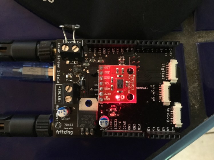 Top
Top
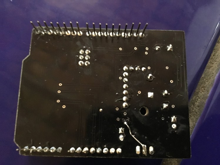 Bottom
Test your setup
Care should be taken in testing to make sure you don’t burn something out... but luck is on my side and it works flawlessly.
To make this project totally viable and actually for real world
I noticed was that the board needs minimum a solar panel of putting out at least 6 volts under full sun and it has to run for at least 8 hours without sun... If needed a larger battery bank or solar panel would be recommended. I also did some power analytics and found that under full broadcast @ 7 volts DC input, the setup draws .525 to 1 amp with fan running so it's using 144 Watt/hours per day, so you need a minimum setup of 12 Volt 5.2 Watt solar panel. The system wouldn't even start broadcasting until it received 7 VDC. So a minimum battery size would be 12 VDC...
Getting connected to Your helium account
 Sign up or log in
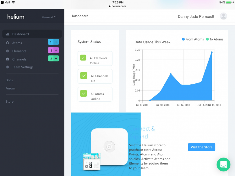 You should have everything talking one atom ,one element ,one getaway
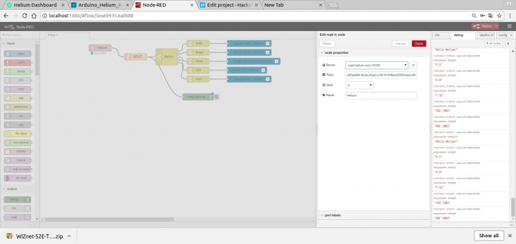
 Click on Helium MQTT
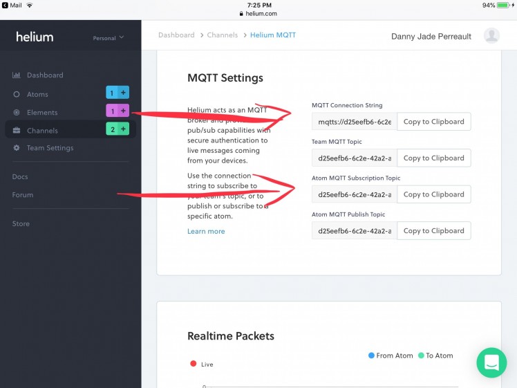 You MQTT connection information
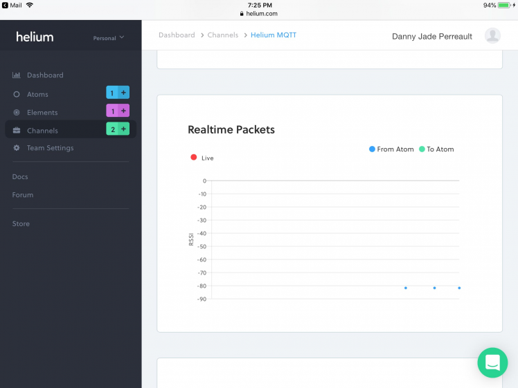 Packets coming out ..If you haven’t uploaded the sketch from Arduino do it now
 Solar calculator
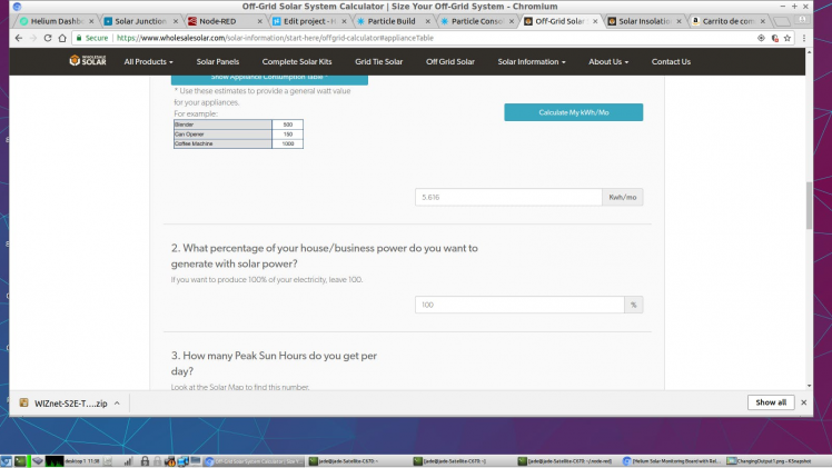 Page 2
Wiring Diagram
- A charge controller isn't really needed for a lead acid battery when your not pulling huge amps or inputting large voltages the Panel can only put so much into the system ..Your panel should only be large enough to charge the Battery..About 2 to 5 Volts over battery voltage unconnected
- the fan is attached to one side of the voltage sensor in order to accurately measure Amps and volts used..The Board can take 24 VDC max so there is lots of room for capacity.
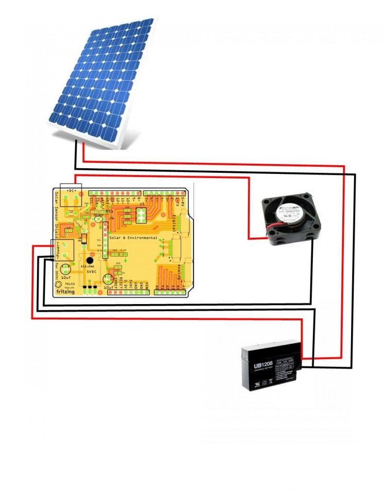 Wiring Diagram
 Testing the board under full sun
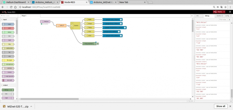
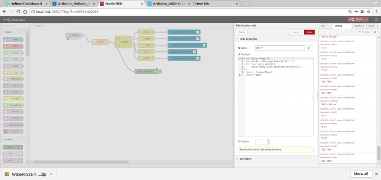
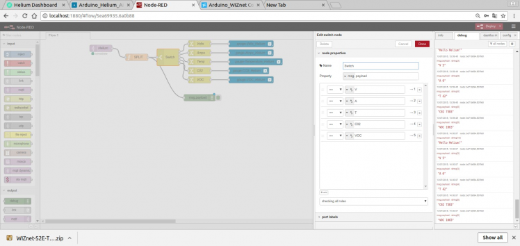
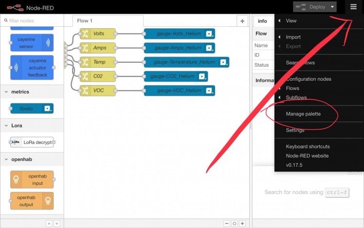
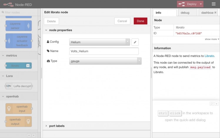
Raspberry Pi Node-RED Programming
I have always said I am definitely not a programmer and design is my forte but here is a simple work around to split you code up and send it to Librato, and as always a picture says a 1,000 words.
Data Analytics Option 1: Librato and Node-RED
When the data comes out of Helium's MQTT it comes out as a string (V 6 : A 2 :T 30: C02 555: VOC 7293) that has to be separated into separate entities before it goes out to Librato and the V:A:T etc has to be stripped out as well and given a label. So no errors are generated. Node-RED is definitely a solution for this...
 Total setup
 Helium setup
 Split configuration
 Separating configuration
Librato setup is extremely easy. First get an account and follow the pictures.
1. After logging in go to Integrations and click on API Tokens
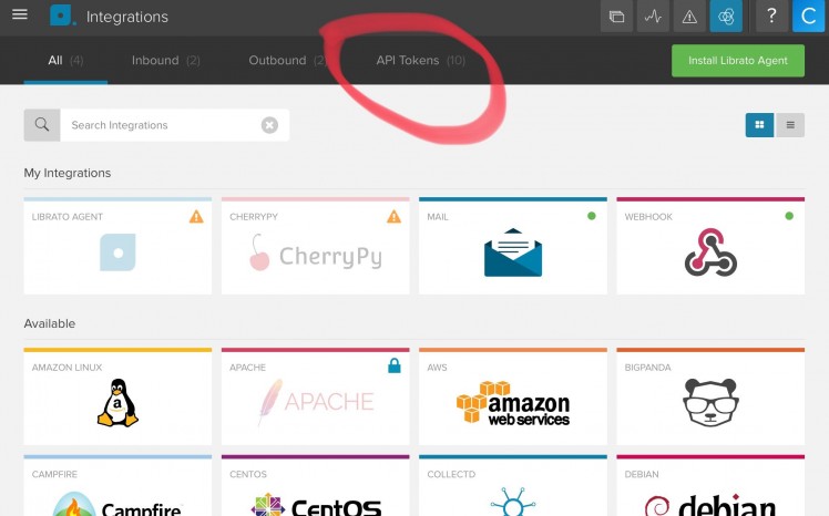 Integrations
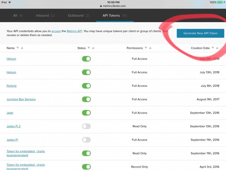
2. In API Tokens click on Generate new API Token
3. Name your integration
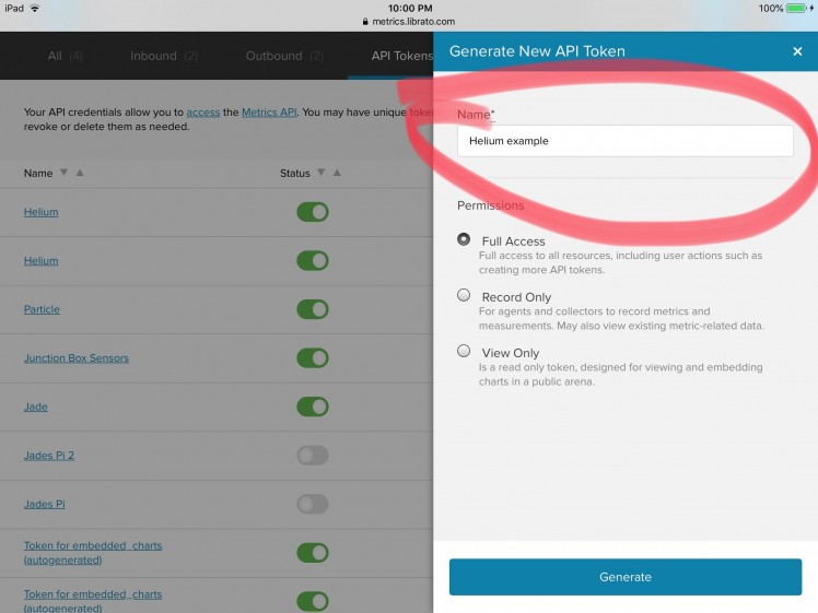 Make up a name
4. Generate your code you will need to copy (CNTL C) the token and make note of the email address above it for the next step.
 Copy this token
 1 / 4 • Installing and configuring the Librato integration
 First line the name you made up. Second line is what going to show up in Librato, Third line is gauge.
YOU ARE DONE... STUFF WILL COME OUT OF LIBRATO.
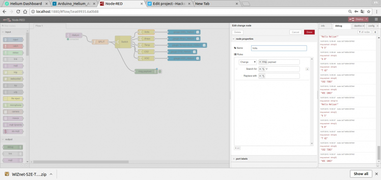 Getting rid of the V,C,A,etc
and the Librato output
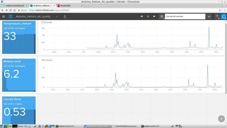 Real-time output to Librato
Putting Your Box Together (with Pictures)
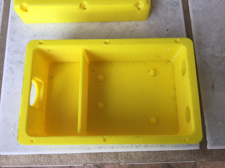
The box will come in out as 7 different parts: main base box, left and right front legs, left and right back legs, lid and solar panel mount, and small solar clips. Build the box completely before putting it all together.
First clean up the 3D print.
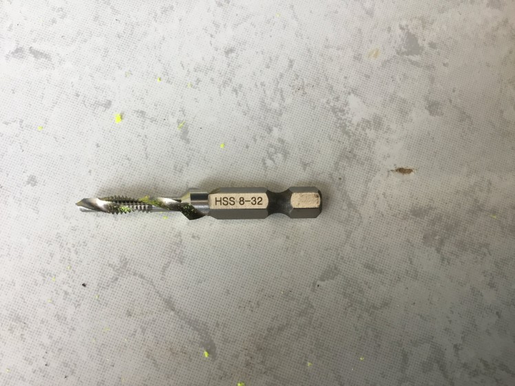 Drill Tap available on Amazon
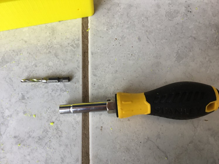
Step 1: Tap all holes with the 8-32 tap tool (by hand) since a drill is too fast. Secure the lid with 8-32 x 1" x 6 (see pictures).
 Everything done by hand
 Tapped holes top ..Untapped bottom
 Tapped holes bottom ..Untapped top ..Tap all holes
 Step 1 Complete
Step 2: Screw on support legs 8-32 x 3/4" x 8
Step 3: Place solar bracket on the top and use an 8/32 drill tap to secure it to the legs but not yet...
Take it all apart
Silicon the Fan into place
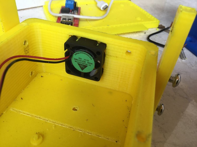 Fan is a 2.5x2.5 cm fan ..Type depends on the voltage your going to run the Fan at eg 5V or 12v
Step 4: Insert the guts and wire up.
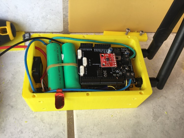 Wiring setup Diagram Below
Step 5: Once you have confirmed operation, screw on the lid with 8/32 bolts.
To make it really pop hex style bolts would be awesome ..
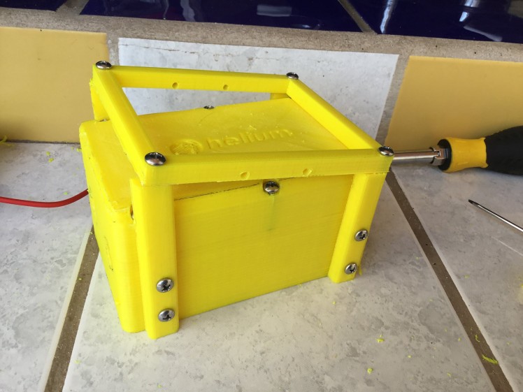
Step 6: Put solar bracket on the top and secure in place with the little brackets.
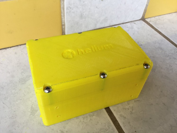
Almost ready to go!

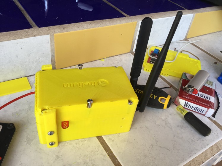
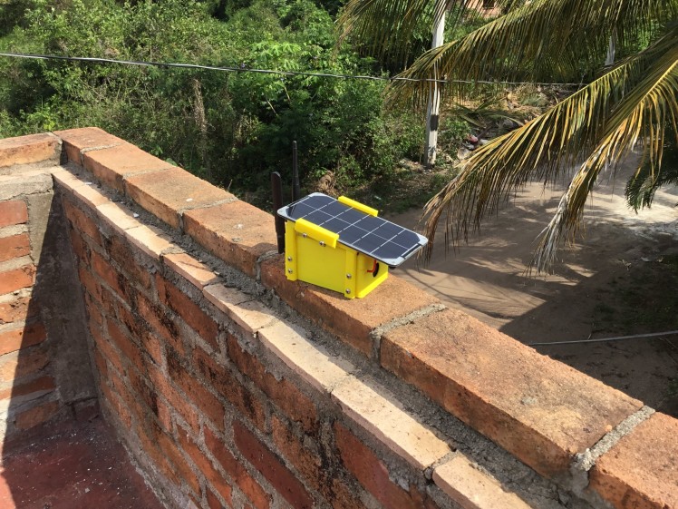 Deployed
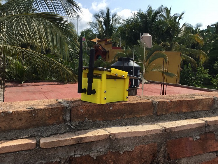 In operation
This is fairly rain tight, once you silicon the antenna holes. The solar panel acts as a rain shield for the rear fan. Let the silicon dry totally before running as silicone and sensors don’t mix. Also, the design has a built-in drain which is necessary unless you want your box to fill up with condensation.
What’s a VOC?
Excerpt From SparkFun.com:
Volatile organic compounds are more or less what they say they are: organic (carbon-containing) compounds that exhibit the property of volatility. Substances can be said to be volatile if they have a very low boiling point, and therefore tend to readily escape into the air at room temperature. The term encompasses a pretty huge collection of materials, including several produced by the human body — every time you exhale, you produce VOC's. Most of the scents and odours that you smell are VOC's, and although many are harmless in normal concentrations, there are also many that are harmful to people and/or the environment.
Day to day, we encounter the highest concentrations of VOCs indoors. Paint, carpets, cleaning materials, machines, people and pets all contain and release VOCs and they tend to accumulate in enclosed spaces without proper ventilation. Human-made (or anthropocentric) VOCs are regulated by law for just this reason.
The health effects of VOCs can be difficult to study because they tend to cause cumulative damage over years of moderate exposure. They don’t pose a significant health risk for normal people living in homes with proper ventilation, but indoor air quality is something worth thinking about. Some specialized HVAC systems even contain sensors to detect rising VOC levels and turn on fresh-air ventilation or air scrubbers.
The legal definition of VOCs, on the other hand, can be harder to nail down. They tend to encompass only a subset of chemically-defined VOCs and vary from country to country depending on the purpose of the legislation where the definition is found. In the US, for instance, many legal definitions of VOCs are concerned specifically with environmental precursors to smog, whereas in Canada the emphasis is placed more widely on substances affecting air quality.
CO2 Equivalent Units
One measurement that causes a lot of confusion is “Equivalent CO2.” The CCS811 will report equivalent CO2 in parts-per-million, but that number can be a little bit deceptive. It’s important to recognize that the CCS811 cannot measure CO2 and that the “equivalent CO2” being reported by the CCS811 has nothing to do with actual CO2 present in the area. So why the heck is it called “CO2 Equivalent Units” and why would anyone need it? The answer comes down to the use of indoor air quality sensors — like the CCS811 — in HVAC control.
Building ventilation, it turns out, is all about occupancy. The more people present in a space, the more CO2 they’re exhaling, and the more ventilation is required. Now, it’s certainly possible to design and operate an HVAC system around the design occupancy of a building or room, in other words the number of people expected to use a space. But this means that you may be wasting energy at times when the building isn’t actually occupied. To solve this problem, many HVAC systems will monitor the concentration of CO2 in a given area in order to calculate the amount of air exchange needed in a scheme called “demand-controlled ventilation.”
Makers of indoor air quality sensors that don’t detect CO2 (in an attempt to market their devices for demand-controlled ventilation systems) have correlated rising CO2 levels in certain environments to rising VOC levels. It’s important to recognize that this is a correlation of the change in levels and not a correlation of the levels themselves: High VOC concentrations are not analogous to high CO2 concentrations. But it can be said that if the VOC concentration of a given space begins to slowly climb above baseline, it probably corresponds to room occupancy and an increase in CO2 (because humans exhale both CO2 and VOCs). Therefore, the manufacturers of these devices report the “CO2 Equivalent Units” with respect to this correlation so that their devices might fit more easily into an existing demand-controlled ventilation scheme.
In my limited research, HVAC experts tend to suggest using real IR-based CO2 sensors in situations where people’s health may be at risk. This doesn’t mean, however, that VOC sensors are unsafe in properly designed systems, or that they don’t have a place alongside CO2 sensors in smart ventilation systems. For instance, VOC sensors can react quickly to non-occupant-related VOC sources and leaking environmental contaminants.
Schematics, diagrams and documents
CAD, enclosures and custom parts
Code
Credits
Related products


Leave your feedback...