
Gps Tracker - Guide

Made by ElectromakerKits / 3D Printing / Fitness / Sensors / Wearables
About the project
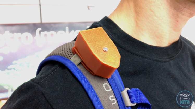
A super simple and small GPS logger with the ability to attach to GoPro Mounts, Straps, Collars or anything else you wish by swapping out its interchangeable mounting adapters.
Project info
Difficulty: Easy
Platforms: TinyCircuits, noads
Estimated time: 2 hours
License: GNU General Public License, version 3 or later (GPL3+)
Items used in this project
Hardware components
|
Gps Tinyshield | x 1 |
|
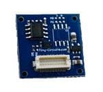
Flash Memory Tinyshield | x 1 |
|
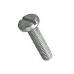
M3 6.0mm Screw Zinc Plated Steel | x 3 |
|
Tinyduino Processor Board | x 1 |
|
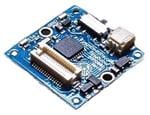
Usb Tinyshield Side Mount | x 1 |
|
Lithium Ion Polymer Battery - 3.7v 70mah | x 1 |

|
Usb Cable A/microb - 3ft | x 1 |
Software apps and online services
|
|
Arduino IDE |
Hand tools and fabrication machines

|
3D Printer | x 1 |
Story
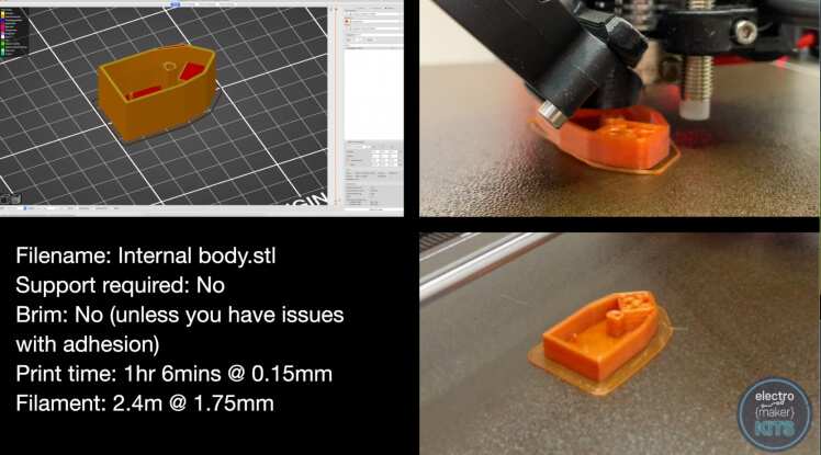
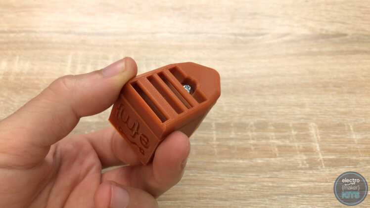
The 3D prints
There are two parts you will need to print for the main housing. Neither of them are very large so I printed them both with 0.15mm layer height and my slicers 'quality' profile selected. If you have problems with adhesion then add a wide brim to the object.

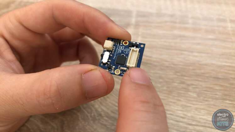
Assembling the electronics
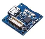
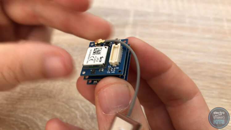
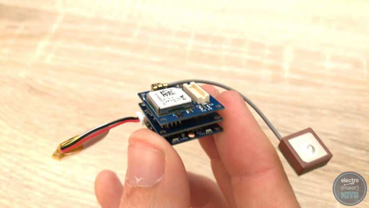
These boards have very easy to use push fittings. These are the large ivory coloured connectors.
The order we stack the boards together does not affect how they operate, however, the housing that you are printing has been designed to accommodate the boards when stacked in a certain order.
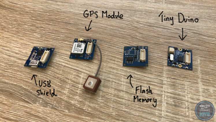
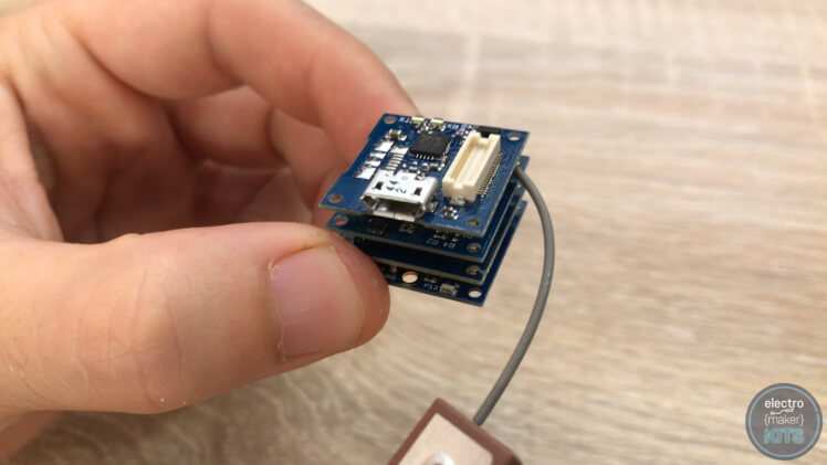
The boards need to be stacked with the main Tiny Duino processor board (shown on the far right) at the bottom. The flash memory board is then stacked on top of the main processor board.

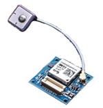
This is then followed by the GPS module.
We will also temporarily add the USB board to the top of the stack. We only require this board to be included in the stack whilst we are communicating with the processor board via USB. When we get to placing it inside the 3D printed housing, we will remove the USB board so as to create as small a finished device as we can to aid with portability.
Programming the board
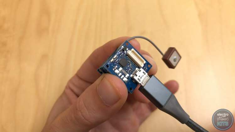
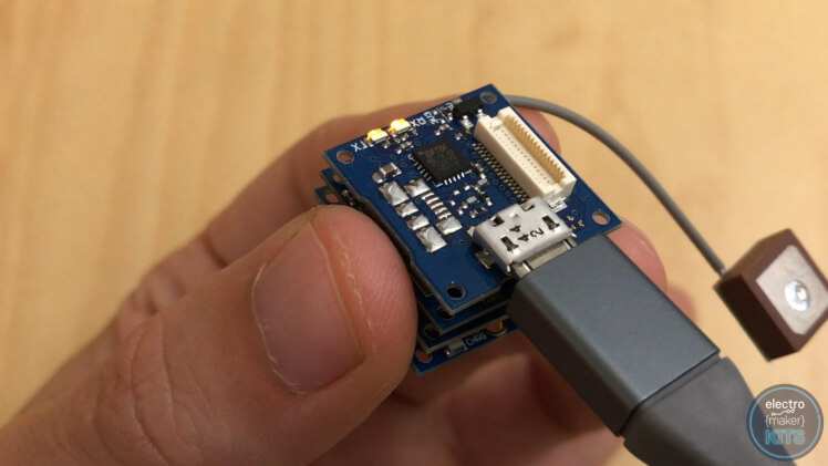
Connect the included USB cable to the USB shield and the other end to your PC.
Launch the Arduino IDE. You can download it from www.arduino.cc if you do not already have it.
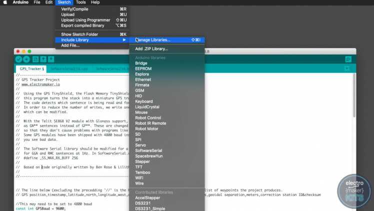
Before we can upload the code you will need the SPI Flash library. To get this, open the Library Manager by heading to 'Sketch' >> "Include Library" >> "Manage Libraries..." in the IDE.
Search for 'SPI Memory' using the search box and then scroll down through the results until you find 'SPIMemory by Prajwal Bhattaram". Press the Install button to install it.
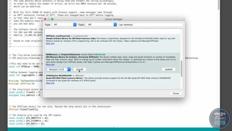
Once this has completed installing you can close the Library Manager window using the button in the bottom right of the window.
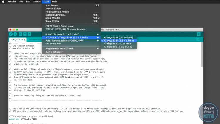
Next, ensure that you have the correct board type and processor selected. Do this by going to "Tools" >> "Board" and selecting "Arduino Pro or Pro Mini". For the processor select "ATmega 328p (3.3v, 8mhz)"
Once this has been verified you can download the code for the project from the Electromaker website (from this projects page) and then upload it to the TinyDuino. Two LEDs, marked TX and RX, will flash during the upload to show that you are communicating via USB with the board.
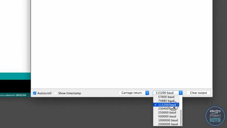
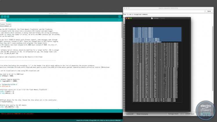
After the upload has completed open the serial monitor within the Arduino IDE and set the baud speed to 115200.
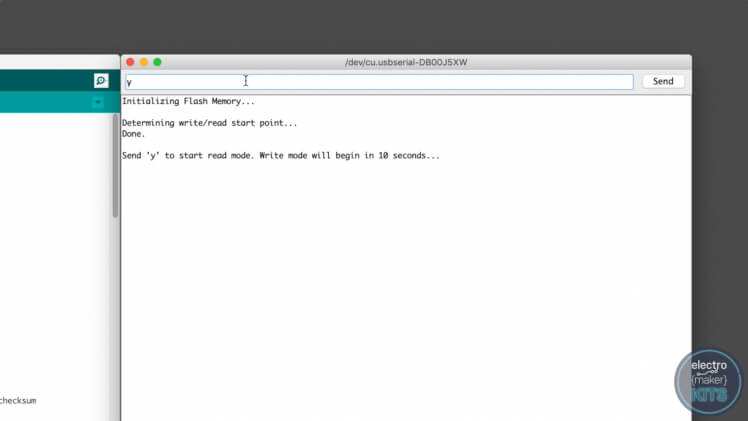
If you reset the TinyDuino or re-upload the code you will see the Arduino IDE will offer us the option to enter 'Read mode' by sending a letter 'y' through the serial monitor. Send the letter 'y'.
If you do nothing for 10 seconds then the board will default to entering write mode and start logging GPS coordinates. If this happens just restart the TinyDuino again.
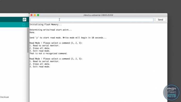
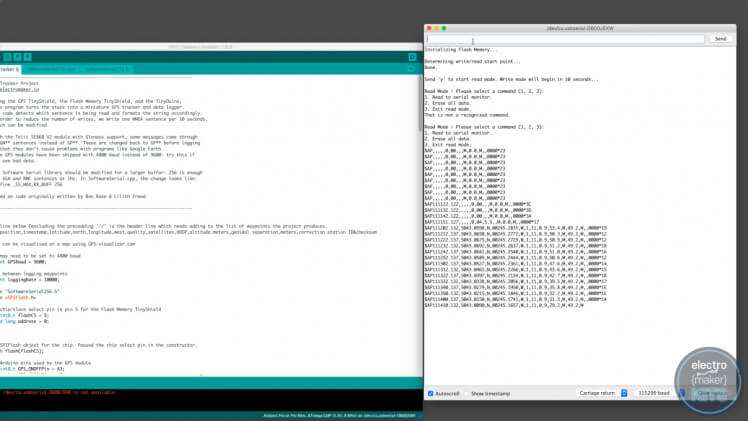
After you have entered read mode you will be presented with three more options:
- Read to serial monitor: This will print all the data waypoints that have been stored on the flash memory to the serial monitor of the Arduino IDE. We will use this after we have tracked a trip to download the data and plot it onto a graphical map.
- Erase all data: Once you have downloaded all the data we will use this option to clear the memory.
- Exit read mode: If you select this the tracker will enter write mode and begin storing GPS waypoints.
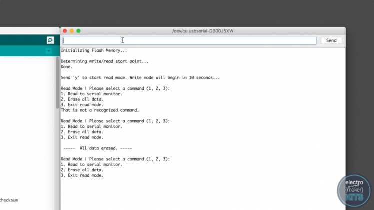
Let's start by erasing the memory to clear any waypoints which may have been logged whilst we assembled and programmed our tracker. To do this send the number '2' to the TinyDuino via the serial monitor. If successful you will receive confirmation that all the data has been erased and then be returned back to the read mode menu.
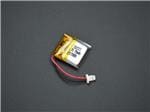
Connecting and charging the Lithium Battery
Ensure that the power switch on the side of the main TinyDuino processor board is off (the lowest board in the stack) and insert the battery lead into the white connector adjacent to the power switch. Connect the project to a powered USB port via the USB connector and the orange charge light should illuminate indicating that the battery is currently charging.

Once the battery has been fully charged the orange light will turn off. We can now remove the USB cable and we'll also remove the USB board from the top of the stack before moving onto installing it into the housing.
Fitting the enclosure
Although the stack of electronic boards has a square footprint their orientation inside the enclosure matters. The white stacking clips need to go against the flat rear wall as shown below:
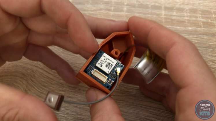
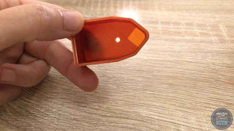
Once gently pushed down into position, carefully curl the GPS antennas cable around the print and position the receiver onto the small pedestal at the pointed end of the print.
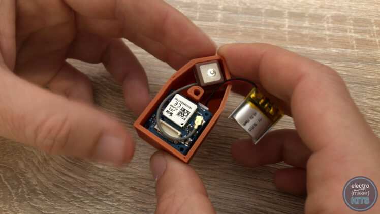
The lithium battery is then positioned on top of the stack of electronics boards.
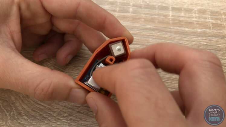
The lid of the enclosure features a very thin layer of plastic over the area that the GPS receiver sits beneath. This is designed to help protect it whilst still allowing it to receive GPS signals. This does not mean that the enclosure is 100% waterproof though without additional precautions being taken.
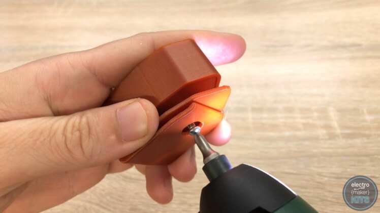
This lid is then slid over the top of the lower housing and its electronics. It's secured in place using one of the included M3 x 6mm screws.

Attachment options
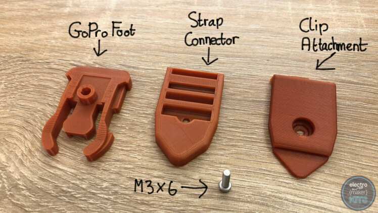
There are three different attachment options which I have already made for you to download and print. They are easily interchanged as they are secured to the main assembly with a single M3 x 6mm screw. If you would like to design your own you can find a dimensioned drawing in the schematics section at the end of this write-up.
I printed all three attachments in PLA with a layer height of 0.15mm. The buckle clip was also printed on its side with a brim and support to help adhesion.
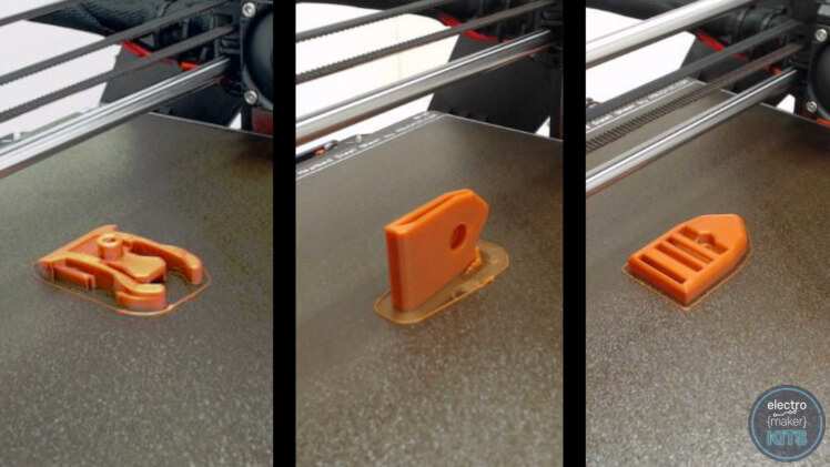
The three ready-made attachment options are:
GoPro Foot
Strap connector
Clip attachment
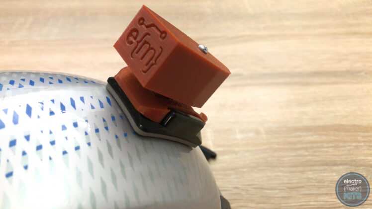
GoPro foot:
This attachment is designed to be compatible with GoPro mountings. Once added it simply slides onto the GoPro base. To remove, pinch the end of the buckle and push backward.
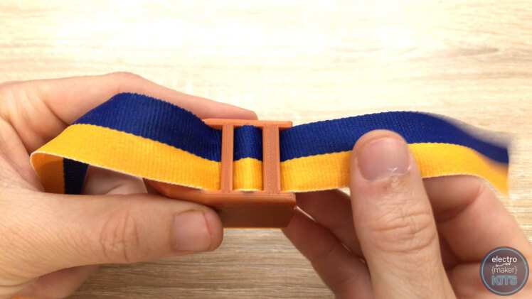
Strap connector
Great for attaching to materials such as the collar of a pet or a belt.
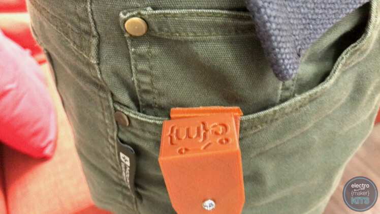
Clip attachment
Good for easily attaching to clothing such as a pocket or rucksack.
Tracking a journey
To begin tracking a journey switch on the tracker using the sliding power switch and then fit it inside its housing. Now add an attachment accessory of your choosing. By the time you have done this the tracker will have defaulted to entering write mode and will begin collecting waypoint information every ten seconds.
To stop tracking just disconnect the battery or slide the power switch to off.
Mapping the data collected
Once you have collected a set of waypoint data we can go through the steps of retrieving the data from the tracker and plotting it onto a map.
Remove the tracker from the housing and add the USB board back onto the top of the stack. Use a USB cable to connect it to your PC. Open the Arduino IDE and then switch on your tracker with the serial monitor open and set to 115200 baud rate. If you do not see the options menu show up as we did earlier then just re-upload the project code to the processor. The GPS waypoint data is saved to the flash memory and so will not be overwritten.
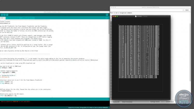
When the menu does show, enter 'y' to enter read mode and then a '1' to read the data to the serial monitor.
Highlight all the rows of data in the serial monitor and copy this into a new plain text document.
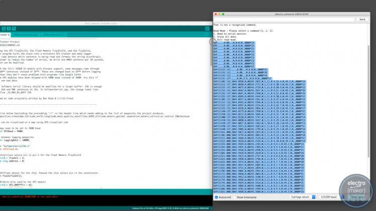
In my data, you can see that a few of the lines at the beginning were recorded to the flash memory when we did not have sufficient GPS data yet to create a complete entry. This is because the device had only just been powered on and was still acquiring enough satellite signals. If you have similar lines in your recording then remove them from the plain text document as I have done.
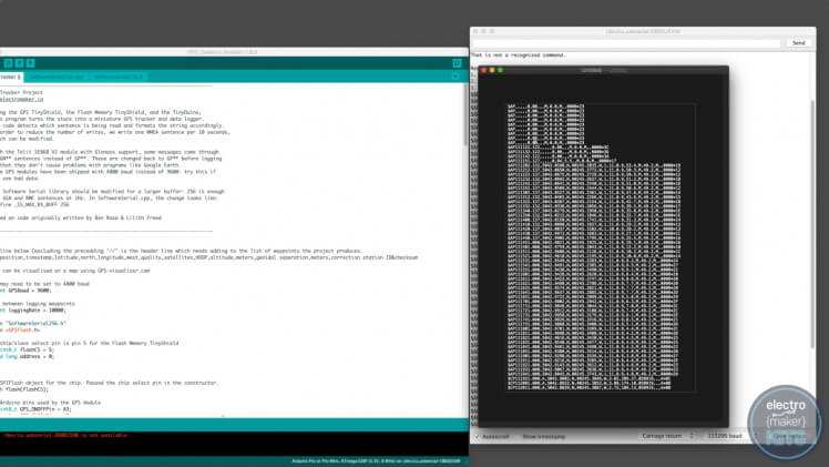
Next, you need to add a new header line to the top of the document which will explain to the mapping software how our data has been formatted. I have put a copy of this line near the top of the project's code (highlighted in yellow below). Copy and paste this so that it is the first line of the document. The same line is also written out here:
GPS position,timestamp,latitude,north,longitude,west,quality,satellites,HDOP,altitude,meters,geoidal separation,meters,correction station ID&checksum
Save the plain text file as a document with the extension .txt.
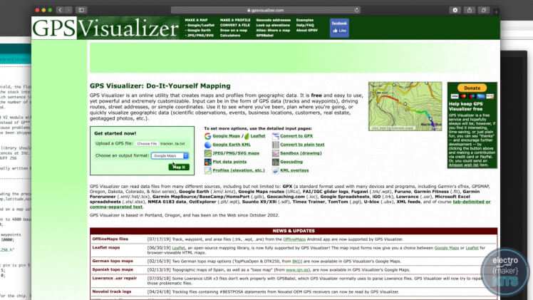
To map these co-ordinates onto a graphical map we will use a free tool provided at www.gpsvisualizer.com.
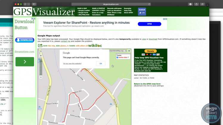
On the front page is a tool to upload the text document we just created. You can then choose an output format. Please do have a look at and try the various options available. For this tutorial select 'Google Maps' as the output.
Press 'Map It' and if all goes as planned the website will return a map of the route traveled.
Don't forget to erase the data on your tracker when you are finished. This way it is ready for the time you want to track something.
Leave your feedback...