

Galdeano Handheld Computer

Made by angel-cabello / 3D Printing / Communication / Home Automation
About the project
It is a python handheld computer with a complete keyboard and a symbolic math engine inside it.
Project info
Difficulty: Moderate
Platforms: MicroPython
Estimated time: 2 weeks
License: GNU General Public License, version 3 or later (GPL3+)
Items used in this project
Hardware components

Story


Details
There are many steps to this project, and we told about them in the log section.
There we told how we have developed:
- the keyboard
- the PCD
- the firmware
- Calculator program
- Graphics program
- IoT program
- Case design
Instructions
Code to the program
https://github.com/otosan-maker/galdeano-lv
It is the micropython code for the calculator
https://github.com/otosan-maker/lv_micropython
this is the code for the firmware, it compiles Eygenmath as a module for mycropython.
Project Logs
New box and new software features
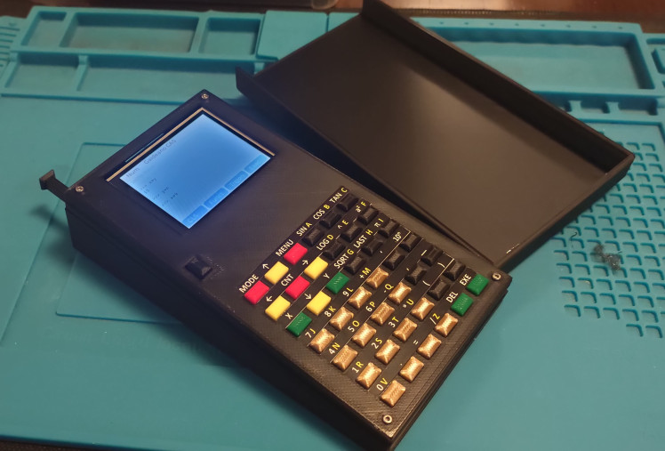
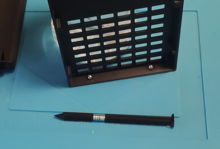
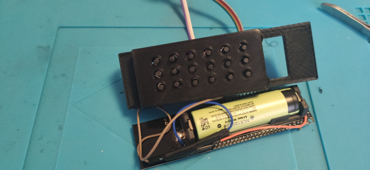
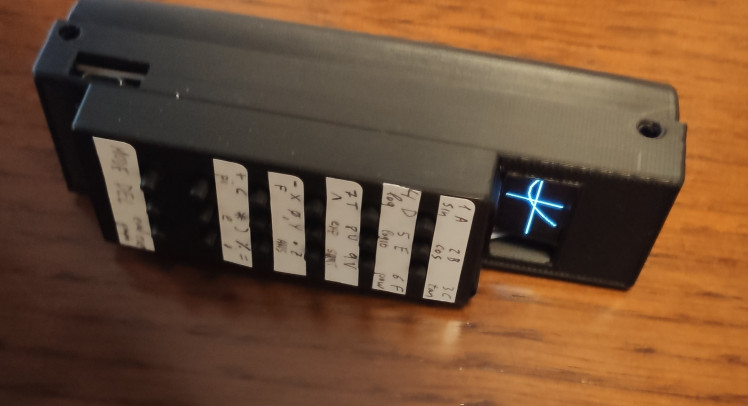
We have developed a new box to the handheld. This one uses a 2 AA batteries box, so we decided to make a box in the shape of a trapezoid.
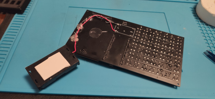
We have added a couple of improvements, a pencil inside the box, with a wire that attaches it to a magnet, so it is fixed in the box. Two-mode magnet help to secure the box to any iron surface.
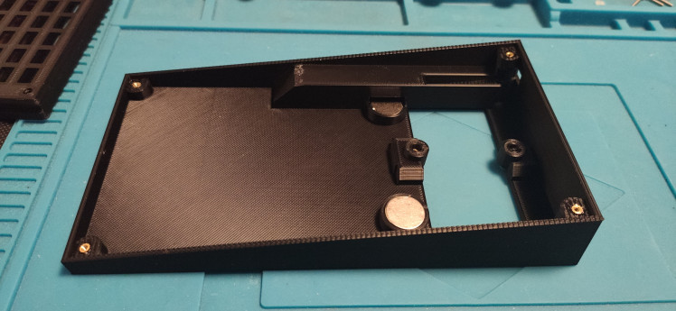
And we have added tape to protect the keys. It is also attached by two magnets. There is also brass pieces to screw the screws
In the software part, we have added history in the calculator. It shows all the executed operations, and the up/down keys navigate through the commands. And have developed a faster way to create function graphs. Now we use a vectorial loop inside the Eigenmath engine to get all the points in one operation.
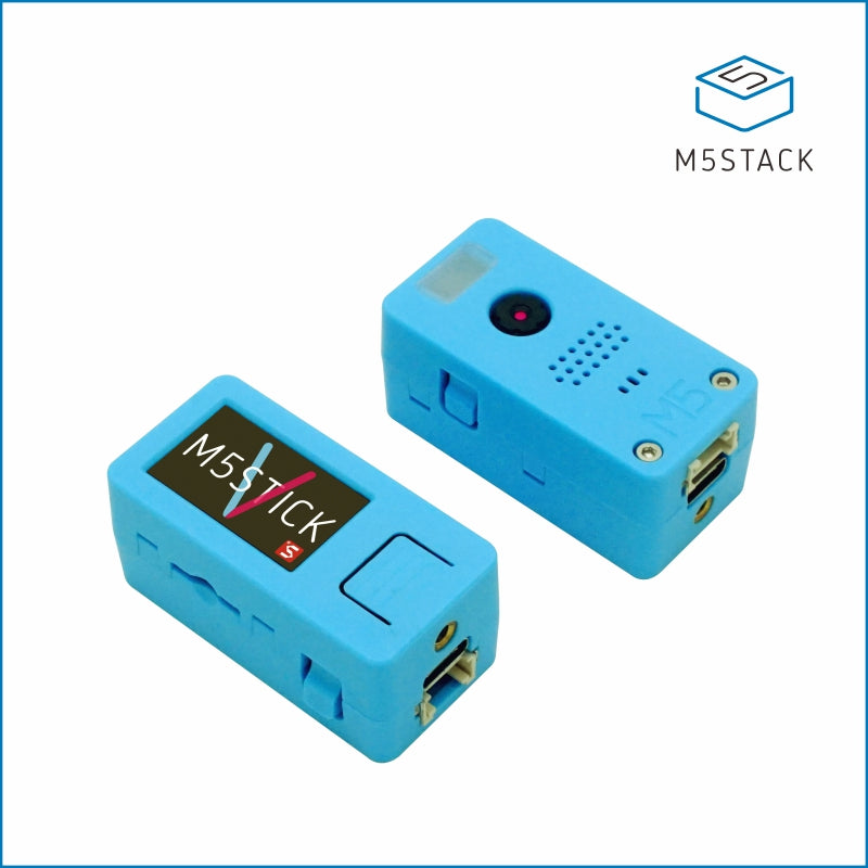
Migrate to M5Stack Core2
Micropython LVGL is compatible with Core2, the Eigenmath math engine is already compiled for esp32, so can our software runs in it? how many modifications are needed to get it working?
The quick answer is yes it can run. And we only need to add a new driver to the keyboard. We use faces keyboard. It is a matrix button and it has a microcontroller to check if a button is pressed. The software is a bit difficult to read, but it communicates the key pressed using an i2c bus. It is also a bit tricky, when we start the bus (Pin 21 and 22) the touchpad sends warning messages. Both devices share the same bus, so the solution is to init the touchpad and copy the buss to use it. The old keyboard driver initiated all the IO pins, so it also broke the i2c bus, it is necessary to delete this old driver. Scanning the bus we get the keyboard address, 0x08, and we can read every 300 milliseconds if a key is pressed.
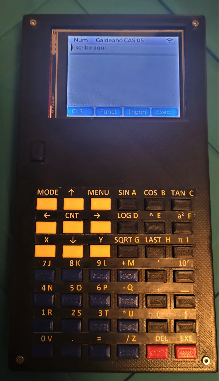
The software - text editor
Any computer needs a text editor. Here we are.
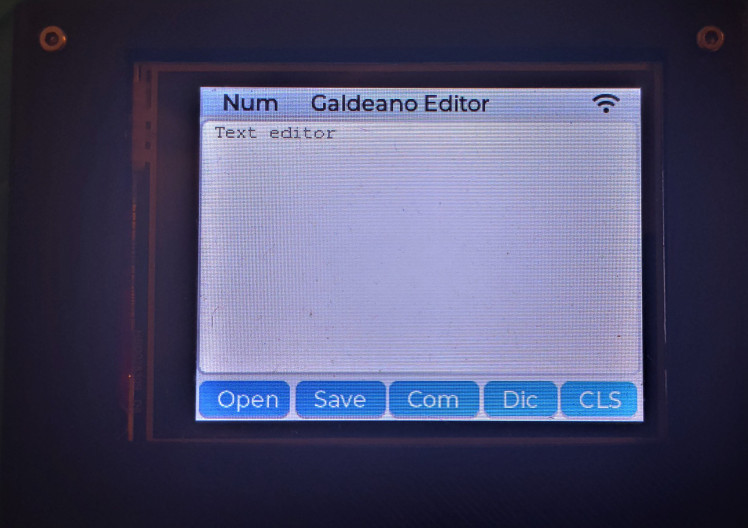
We can write in the screen, we can open a store file.

Edit it and store it with the help of the Save button.
The CLS button clears the screen. If we save the file and the screen is empty the program deletes the file.
The Com button reads the file line by line, and executes in the math engine these lines, adding the output to the file out.txt.
The Dic button shows the Eigenmath most used functions.
The software - IoT programs
The main use of this handheld is to control the house-connected devices. We have developed a few programs to show how to do it.
The first one is a WIFI config program.
At the top, it shows us the wifi SID and password used to connect, a dropdown menu, where the wifis available are (after a scan) and a textbox to introduce the password to the new wifi connection.
The checkbox shows if we start the wifi connection at startup or if we will do it manually. If we use only the calculator software it is better to disable it, if we are going to control devices, we should check it.
If we press the Wifi On/Off button we connect / disconnect, save button stores our credentials. When the wifi is on a python timer shows a Wifi symbol in the head and hides it when we disconnect.
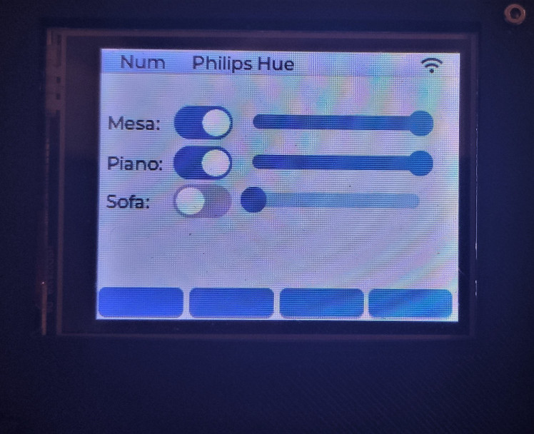
The second one is a panel control of my Philips Hue system. I have three light groups and it enables me to switch it on/off or control the brightness.
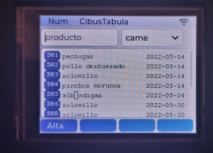
the other two are custom home projects, one is for food storage, CibusTabula.
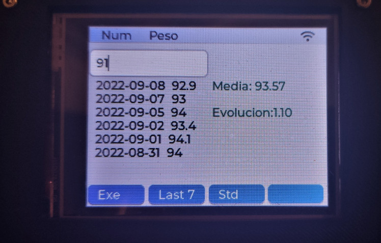
and the other is for weight control
The software - graphycs
To complete the calculator software that this handheld has we need a function graphics program.
If we push the menu button, we get a window with all the programs defined there, the second raw shows our next objective. At the right it is the configuration screen.
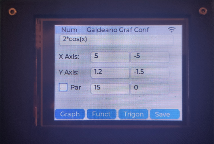
At the top, we can write the formula we want to see as x function. We can uses any function we have defined in the math engine, so if we have defined f(x) in the calculator app, we can write only f(x) an it will show.
Next is the X - Y range.
If we press the save button, it will store the data to a file.
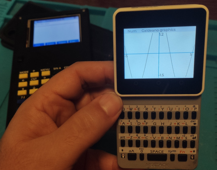
And if we press the Grap button, we go to the plot screen.
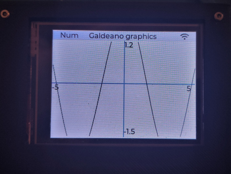
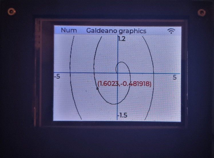
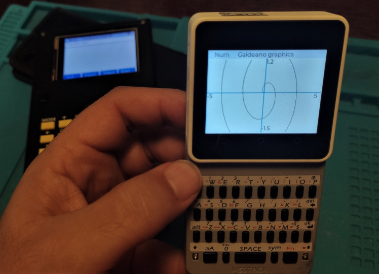
If we choose the Par checkbox in the config screen, the screen changes and shows that
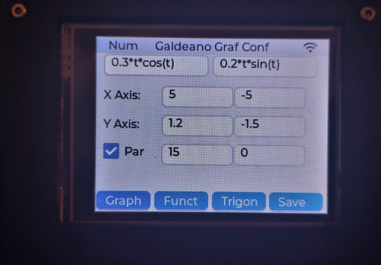
We are in the parametric equations. We can write x(t) and y(t) at the top, and the t - range at the bottom, we can store a f(x) and a x(t)-y(t) at the same time in the file. Pressing the graf button takes us to this screen
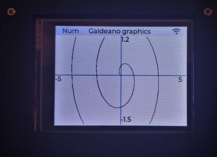
When we are on this graph screen we can press the left-right hardware buttons (yellow) and it will appearance the (x,y) coordinates.

Pressing the MENU key we can go to another program.
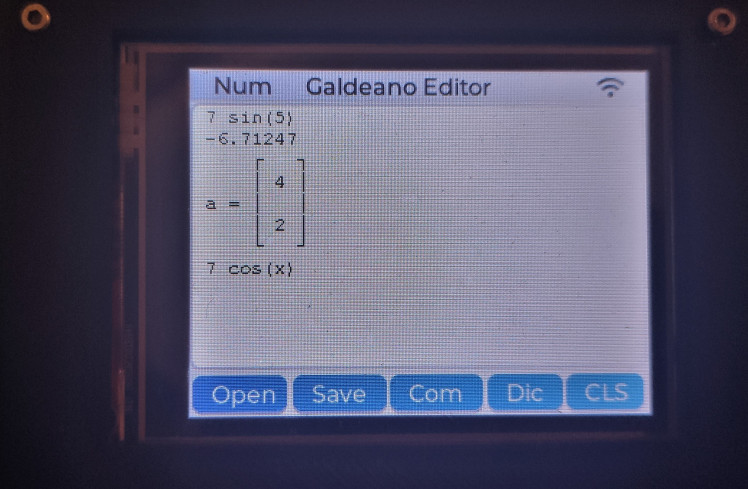
The software - the calculator
Once the firmware is ready we start programming the handheld.
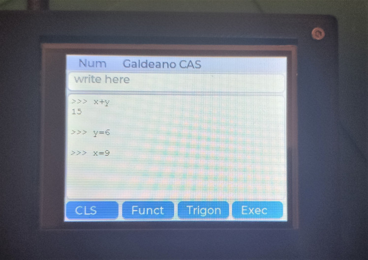
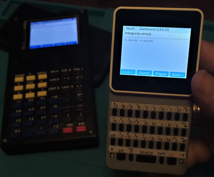
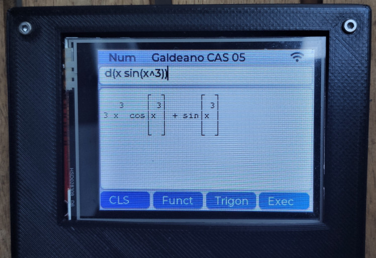
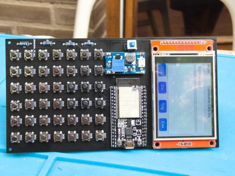
The first program is a CAS (Computer-assisted system) calculator. We can introduce one formula and the computer resolves it. We can use a rich language to express these math equations.

we can use the MODE key to switch between the NUM mode, the one that uses the math expression, and alp and ALP, the alphabetical normal and CAPS mode. The head of the screen shows the mode we are in.
The expression is written in the upper entry box and when we press the EXE physical red button or the Exec button on the screen, it is evaluated and shown in the bottom box.
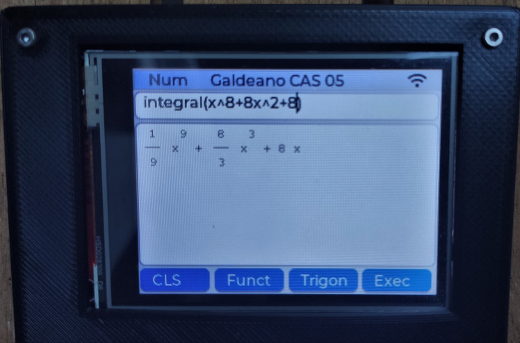
The Func button shows a menu of topical Eigenmath functions, as d() that calculates de derivate or integrate() that calculates the integration of the function.
The Trigon button shows a menu with all the trigonometric functions, in the keyboard there are only the 3 main ones.
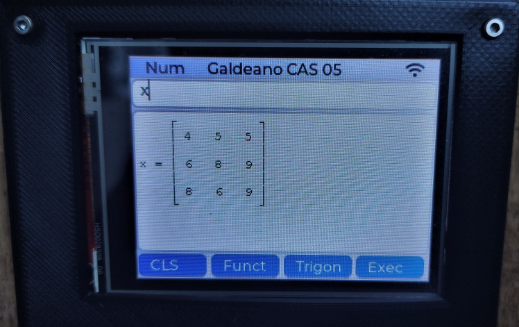
We can define functions with the = symbol, as a matrix of any dimension.
The best way to learn is to visit Eigenmath home page.
The software, creating the firmware.
We want to create a graphical computer, and the best library for it is LVGL. and we want to program this computer and made it easy to program with it, so we choose micropython as the programming language.
But we want also to create a computer with symbolic math, so we need a symbolic math engine. There are many of them, but no one has migrated any to an esp32. But it was just C .... so we choose Eigenmath as the math engine because it is plain C.
First, we migrated Eigenmath to esp32, it is easy and we have only a few memory issues. The main problem is the amount of memory that esp32 can use as stack memory (local variables) so we change a few to heap (malloc() them ). A few small fixes after that it compiles and works fine.
Now we have to get a custom micropython with LVGL support. We downloaded the software to git and compiled it with Eigenmath. We share the RAM between both programs, 2Mb to any (we use a WROVER module with 4 MB of SPI RAM).
But we need to communicate from python to Eigenmath, so we created a special python module, Eigenmath, with only a function, that reads a string, runs it in the math engine, and responds with a string from there. Another problem arises. Eigenmath uses UTF characters to draw mathematic formulae. We add a custom font, called Galeano, with these characters to micropython.
The firmware grew too much, so we alter the partition table so the app partitions were greater, and reduce the data (where the python files are) partition.
We also customized the ili4385 driver to use our IO pin setup (SPI) and we can create the screen object easily.
But we have an unresolved problem with the SD card. It is a software problem because we can use the screen and the SDcard with Arduino programs. The SPI bus is the same, and even when we use the lv_spi interface (that claims to solve it) we have problems with the bus initialization.
Create the PCB
So for the next microcomputer with a keyboard, we will use a PCB to connect all the components. And it is the first step, to create a list of the components.
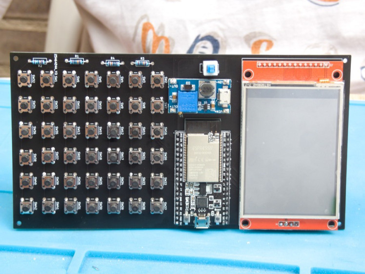
We will use esp32 as the microcontroller, we know it well and it is quite a computer powerful. And it has one great advance, it starts up in a few seconds. We don´t want to wait minutes for a computer to start up, and we prefer to shut down the device to save battery life.
The screen is a common screen with a good resolution, 320x240, colorful, and an SPI interface. We saw a module with a touchpad and SD card so we go that way.
The buttons are normal switches.
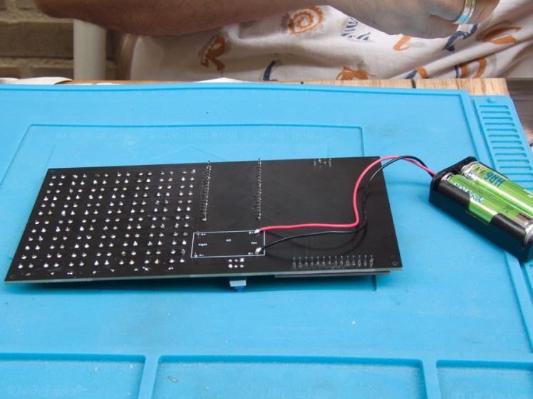
The other problem is the battery, we are not sure what is the right way, so we uses two ways, AAA batteries, and lipo. The first only needs a boost-converter to go from 2.4-3 Volts to 3.3. The lipo uses a battery charger, and a buck-boost converter, because lipo go from 4.7 volts to 3.3.
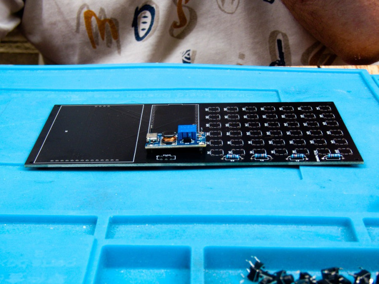
And we used Kicad to develop the PCB, and in a few weeks we got the first prototype. The screen was placed in reverse, and we need 4 resistance to pull up 4 IO pins that do not have internal resistance.
This second prototype works great, and we mount the components in there.

And it works !!!!!!!!!
Next step the software.
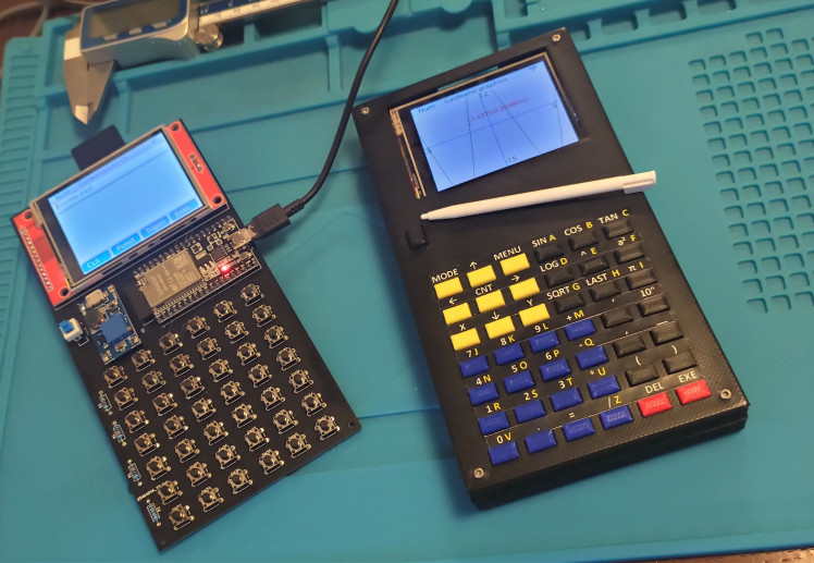
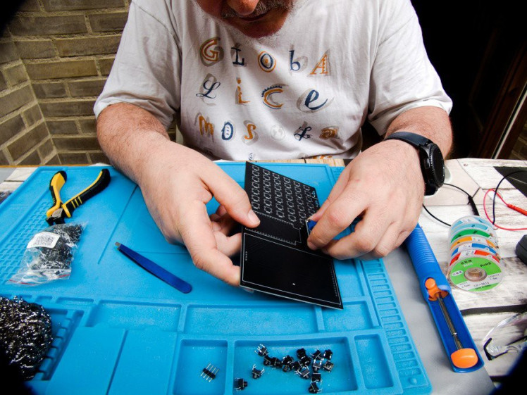
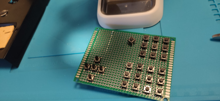
I've always wanted to make my own keyboard
The original idea behind this project is to develop a keyboard. So I prepare this first try with wires. At first, it is easy, it only has 3x6 buttons
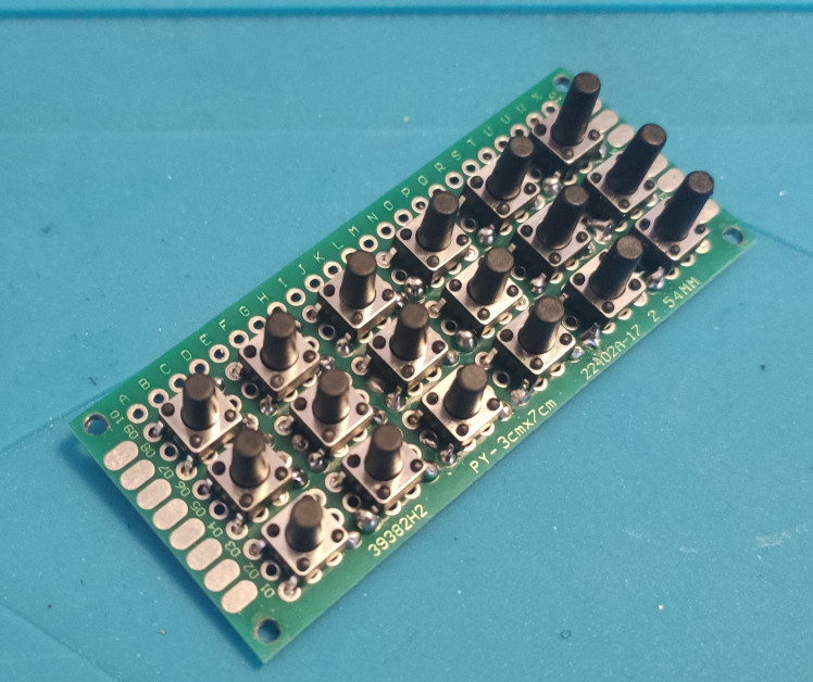
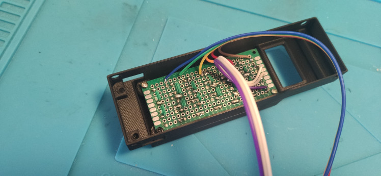
We connected it to an esp32 with a lipo battery and use a 3D printed case.
We use 3 IO Pins to output a voltage, one pin at a time, and look for the voltage in the other 6 pins to detect the key pressed. It only works if we press one key at any time, but for a calculator is enough.
The calculator is programmed in micropython, using the eval function to evaluate the math formulas we introduce. We have created even a small graphic plotting of the function.
But when we increase the number of keys .... using wires to connect the buttons is a mess that we can't resolve ... so we will go the PCB way :-D
Credits
Related products


Leave your feedback...