
Esp8266 And Visuino: Wi-fi Network Scanner

Made by Ron / Communication / Displays / IoT
About the project
Creating a Wi-Fi Scanner with ESP8266 NodeMCU - quick and easy!
Items used in this project

Software apps and online services
Story
ESP8266 modules are great low cost stand alone controllers with built in Wi-Fi. In this Tutorial, I will show you how you can easily make a Wi-Fi network scanner with an ESP8266.
In the Tutorial, I will use NodeMCU module version 0.9. The NodeMCU is the easiest way to program and experiment with ESP8266 controllers. This Tutorial, however, can easily be done with any other module ESP8266, even ESP-01.
Step 1: Components
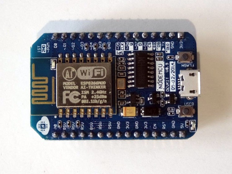
One NodeMCU ESP8266 board (I used NodeMCU 0.9, but any other ESP8266 will work)
Step 2: Start Visuino and select the ESP8266 Board type
1 / 2 • Picture 1

Picture 1

Picture 2
To start programming the Arduino, you will need to have the Arduino IDE installed from here: http://www.arduino.cc.
Please be aware that there are some critical bugs in Arduino IDE 1.6.6.
Make sure that you install 1.6.7 or higher, otherwise this Tutorial will not work!
The Visuino: https://www.visuino.com also needs to be installed.
- Click on the "Tools" button on the Arduino component (Picture 1) in Visuino
- When the dialog appears, select "NodeMCU ESP-12" as shown on Picture 2
1 / 3 • Picture 1

Picture 1

Picture 2

Picture 3
- In the Object Inspector expand the "Modules" property, then the "WiFi" sub-property (Picture 1)
- In the Object Inspector select the "Operations" property and click on the "..." button next to its value (Picture 1)
- In the "Operations" dialog, select the "Scan WiFi Networks" item from the list on the right (Picture 2)
- Click on the "" button (Picture 2) on the left to add one ScanNetworks item (Picture 3)
- Close the "Operations" dialog
1 / 2 • Picture 1

Picture 1

Picture 2
- Type "clock" in the Filter box of the Component Toolbox, then select the "Clock Generator" component (Picture 1) and drop it in the design area
- Connect the "Out" pin of the ClockGenerator1 component to the "Scan" input pin of the "Modules.WiFi.Operations[0]" item of the "NodeMCU ESP-12" component (Picture 2)
1 / 5 • Picture 1

Picture 1

Picture 2

Picture 3

Picture 4

Picture 5
We need to print the header text when the scanning starts. The "Scanning" pin will generate clock even every time it changes value from False to True and back. To generate event only when it changes from False to True, we need to use Detect Edge component.
- Type "edge" in the Filter box of the Component Toolbox then select the "Detect Edge" component (Picture 1), and drop it in the design area
- Type "text" in the Filter box of the Component Toolbox then select the "Text Value" component (Picture 2), and drop it in the design area
- Connect the "Scanning" output pin of the "Modules.WiFi.Operations[0]" item of the "NodeMCU ESP-12" component to the "In" pin of the DetectEdge1 component (Picture 3)
- Connect the "Out" output pin of the DetectEdge1 component to the "In" input pin of the TextValue1 component (Picture 4)
- Connect the "Out" output pin of the TextValue1 component to the "In" input pin of the "Serial[ 0 ]" channel of the "NodeMCU ESP-12" component (Picture 5)
1 / 2 • Picture 1

Picture 1

Picture 2
- Select the TextValue1 component (Picture 1)
- In the Object Inspector select the "Value" property and click on the "..." button (Picture 1)
- In the "Value" editor type:"""Scan""-----------------"(Picture 2, each bracket is a new line as shown.)
- Click on the OK button to close the dialog
1 / 6 • Picture 1

Picture 1

Picture 2

Picture 3

Picture 4

Picture 5

Picture 6
We will use Formatted Text component to format and print each detected Wi-Fi Hot Spot information line.
- Type "text" in the Filter box of the Component Toolbox, then select the "Formatted Text" component (Picture 1) and drop it in the design area
- Click on the "Tools" button of the FormattedText1 component (Picture 2)
- In the Elements editor, select the Text Element on the right and click on the "+" button on the left to add one of them (Picture 3 and 4)
- In the Elements editor, select the Integer Element on the right, and click 2 timeson the "" button on the left to add 2 of them (Picture 4 and 5), then close the Elements editor
- In the Object Inspector, set the value of the Text property of the FormattedText1 component to "SSID: "%0" Signal: %1 Channel %2" (Picture 6). The %0 will be replaced with the value from TextElement1, %1 will be replaced with the value from IntegerElement1, and %2 will be replaced with the value from IntegerElement2
1 / 5 • Picture 1

Picture 1

Picture 2

Picture 3

Picture 4

Picture 5
- Connect the "SSID" output pin of the "Modules.WiFi.Operations[0]" item of the "NodeMCU ESP-12" component to the "In" pin of the TextElement1 of the FormattedText1 component (Picture 1)
- Connect the "Signal Strenght" output pin of the "Modules.WiFi.Operations[0]" item of the "NodeMCU ESP-12" component to the "In" pin of the IntegerElement1 of the FormattedText1 component (Picture 2)
- Connect the "Channel" output pin of the " Modules.WiFi.Operations[0]" item of the "NodeMCU ESP-12" component to the "In" pin of the IntegerElement2 of the FormattedText1 component (Picture 3)
- Connect the "FoundNetwork" output pin of the "Modules.WiFi.Operations[0]" item of the "NodeMCU ESP-12" component to the "Clock" input pin of the FormattedText1 component (Picture 4)
- Connect the "Out" output pin of the FormattedText1 component to the "In" input pin of the "Serial[ 0 ]" channel of the "NodeMCU ESP-12" component (Picture 5)
1 / 2 • Picture 1

Picture 1

Picture 2
- In Visuino, press F9 or click on the button shown on Picture 1 to generate the Arduino code and open the Arduino IDE
- Connect the NodeMCU module with USB cable to the computer
- Select the board type and serial port as I have shown you in this Tutorial
- In the Arduino IDE, click on the Upload button, to compile and upload the code (Picture 2)
1 / 2 • Picture 1

Picture 1

Picture 2
Congratulations! You have made a Wi-Fi scanner.
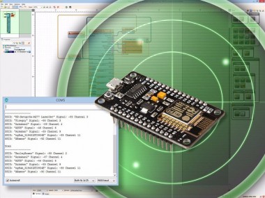
The Video shows the connected and powered up project.
If you open Serial Terminal in the Arduino IDE or Visuino, you will see the Wi-Fi hot-spots discovered by the NodeMCU, their strength, and their channel (Picture 1)
On Picture 2, you can see the complete Visuino diagram. Also attached is the Visuino project that I created for this tutorial. You can download and open it in Visuino: https://www.visuino.com
Credits
Related products


Leave your feedback...