
Esp32 Uwb Indoor Positioning Test

Made by Makerfabs01 / Sensors / IoT
About the project
ESP32 UWB Indoor Positioning Test
Project info
Difficulty: Easy
Estimated time: 3 hours
License: GNU General Public License, version 3 or later (GPL3+)
Items used in this project

Story
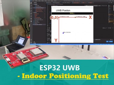
We made an ESP32 UWB indoor positioning test, using 2 UWB anchors and 1 UWB tag, when the tag is moving, the real-time position of the UWB tag can be graphically displayed on PC.
Supplies
- ESP32 UWB *3
- Power bank
- 5v power supply *2
Step 1: Overview
1.1 Introduce
DW1000 is the world's first single-chip wireless transceiver based on Ultra-Wideband techniques. It provides a new approach to real-time location and indoor positioning systems, location-based services, and wireless sensor networks. It enables to develop cost-effective RTLS solutions with precise indoor and outdoor positioning to within 10 cm.
The Makerfabs ESP32 UWB is based on ESP32 and DW1000 solutions, it acts like a continuously scanning radar, that precisely locks onto another device and communicates with it, thus calculating its own location, with the ESP32 WiFi/Bluetooth, it could be a solution for wireless indoor positioning.
1.2 About UWB
Ultra-wideband is a technology for transmitting information across a wide bandwidth (>500 MHz). This allows for the transmission of a large amount of signal energy without interfering with conventional narrowband and carrier wave transmission in the same frequency band. Regulatory limits in many countries allow for this efficient use of radio bandwidth, and enable high-data-rate personal area network (PAN) wireless connectivity, longer-range low-data-rate applications, and radar and imaging systems, coexisting transparently with existing communications systems.

A significant difference between conventional radio transmissions and UWB is that conventional systems transmit information by varying the power level, frequency, and/or phase of a sinusoidal wave. UWB transmissions transmit information by generating radio energy at specific time intervals and occupying a large bandwidth, thus enabling pulse-position or time modulation. The information can also be modulated on UWB signals (pulses) by encoding the polarity of the pulse, its amplitude and/or by using orthogonal pulses. UWB pulses can be sent sporadically at relatively low pulse rates to support time or position modulation, but can also be sent at rates up to the inverse of the UWB pulse bandwidth. Pulse-UWB systems have been demonstrated at channel pulse rates in excess of 1.3 billion pulses per second using a continuous stream of UWB pulses (Continuous Pulse UWB or C-UWB), while supporting forward error-correction encoded data rates in excess of 675 Mbit/s.
1.3 UWB Ranging
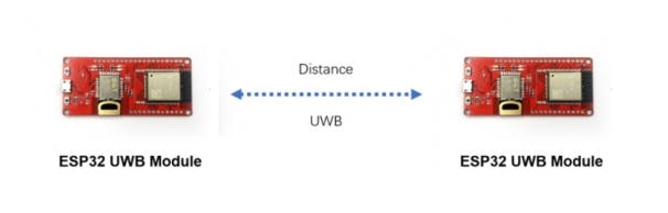
A UWB radio system can be used to determine the "time of flight" of the transmission at various frequencies. Of course, the speed of the "flight" is as that of light, so the core problem is how to check the "flight" time, and thus to calculate the distance.
Distance =Speed of light * Tprot
For the most basic system, there at least 2 items: Device_A(called A) and Device_B(called B), there mainly 2 measure way:
- Single-sided Two-way Ranging
- Double-sides Two-way Ranging
1.3.1 Single-sided Two-way Ranging
This is the most basic way of measuring:
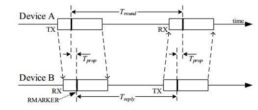
Firstly A send the message(TX) and have a record of the time Mark, As B get the message, and have the recode of time Mark, after delay(Treplay), B send the message (TX) and have a record of the time mark, and finally A receives the message, and have the record of time mark.
Then the flight time:
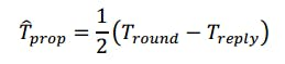
As the Tround and Treply are stored at the same device, so the time-error offset; of course, there error between A(eA) and B(eB), and the error is:
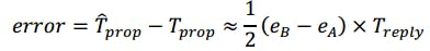
That is, the error is linear to the Treply. So this way is not popularly used, only suit for very short distance measuring.
1.3.2 Double-sided Two-way Ranging
After the "Single-sided Two-way Ranging", if A feedback again to B, it will be :
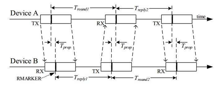
This measurement we called 3 messages mode.
After the "Single-sided Two-way Ranging", if B initiates again another message and A feedback, it will be :
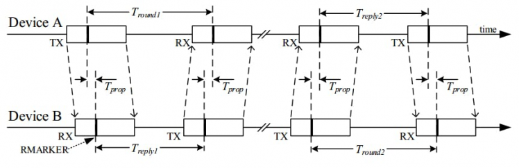
This measurement we called 4 messages mode.
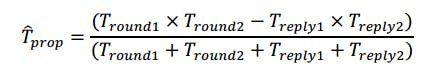
In either 3-message mode or 4-message mode, the flight time is calculated as:
Step 2: Indoor Positioning With ESP32 UWB
2.1 View
In this application, we used 3 Makerfabs ESP32 UWB modules, 2 modules acting as the UWB anchor, and 1 as the UWB tag, that moves in the room. As the tag gets its position, it transmits its location to devices(either PC browser, of the app at phone), to show the real-time position.
 2.2 Plane orientation algorithm
Assume that all three UWB modules are at the same horizontal height. UWB can get the distance between Tag and two anchors, plus the distance of two anchors set in advance, we can get the length of three sides of a triangle.
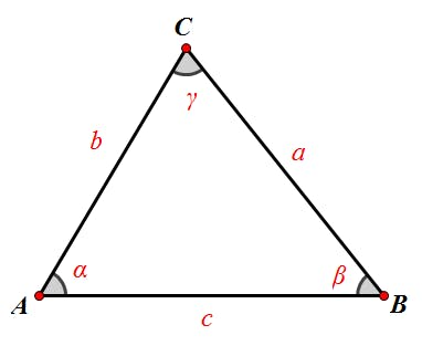
Two points "AB" are two anchors respectively, and "C" is the point of tag. "c" is the distance of two anchors, and UWB will get two lengths "a" and "b". Tag is "b" away from point "A" and "a" away from point "B".
Now that we know the distance between the three sides of the triangle, we can calculate the coordinates of point "C".
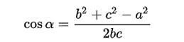
I used the law of cosines to calculate the cosine of Angle "A":
I have the Pythagorean Theorem that gives me the sine of Angle "A":
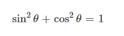
cos_a = (b * b + c * c - a * a) / (2 * b * c)sin_a = sqrt(1 - cos_a * cos_a)
If we set point "A" as the origin of the coordinate system (0, 0), then we get point C (bcosα, bsinα).
Step 3: Code Explain
3.1 Library
We use arduino-dw1000 library. A library that offers basic functionality to use Decawave's DW1000 chips/modules with Arduino (arduino-dw1000 library)
Please Note to modify the DW1000 library according to Github, otherwise it will not compile for ESP32. The guide at ESP32 UWB GitHub.
***The full code for this application at Makerfabs GitHub***
3.2 Device_Anchor
As there 2 anchors in the system, we need to set different anchor addresses for the two anchors.
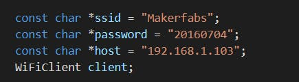
#define ANCHOR_ADD "83:17:5B:D5:A9:9A:E2:9C"// modify the address when multiple anchors, such as 83/82.The library uses random short addresses by default, and we need to set it to use the static addresses we set. So we need to set the UWB module to Anchor mode, LONGDATA_RANGE_LOWPOWER mode, and turn off random short addresses, by the following code:
DW1000Ranging.startAsAnchor(ANCHOR_ADD,
DW1000.MODE_LONGDATA_RANGE_LOWPOWER, false);
The Anchor code at: https://github.com/Makerfabs/Makerfabs-ESP32-UWB/tree/main/example/anchor
3.3 Device_Tag
The tag needs to read the distance between the two anchors and send it to PC through UDP protocol.
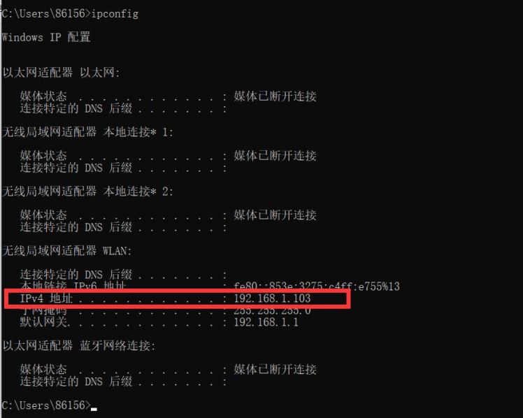
Firstly, set WiFi and target IP address (PC).
In Windows cmd, using "ipconfig" to check PC local IP.
And set UWB work in tag mode.

I used a Linked list to store the detected anchors, which fits well with the way UWB works. The content of the linked list is converted into JSON format.
The obtained JSON string format is as follows:
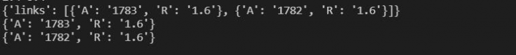
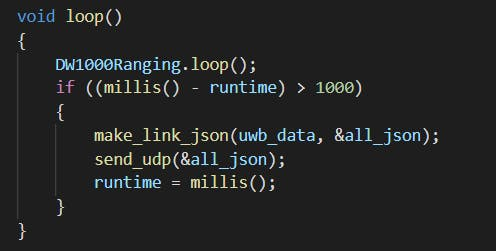
Finally, data is sent to PC every second through the UDP protocol.
The tag code at: https://github.com/Makerfabs/Makerfabs-ESP32-UWB/tree/main/example/IndoorPositioning/udp_uwb_tag
3.4 Python Code
A simple demo to calculate the position of the tag and graphically display it. Using turtle to draw.
In the beginning, I wanted to use Matplotlib, but it was a bit complicated. Turtle is easy, but the functions provided are rudimentary. I added some drawing functions myself to quickly draw lines, circles, rectangles, etc.
Here is my position calculation function.
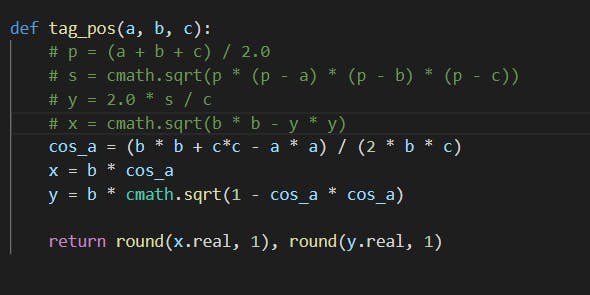
In fact, at first, I used Helen's formula to calculate the coordinates, but couldn't tell whether a triangle was acute or obtuse.
The function of the demo is to receive the data of the tag transmitted through UDP protocol, calculate the position of the tag and draw it on the screen.
Step 4: Indoor Positioning Test
After all the UWB anchors& tags are programmed OK, firstly I place the two UWB anchors on both sides of the table.
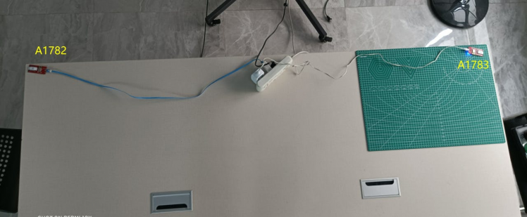
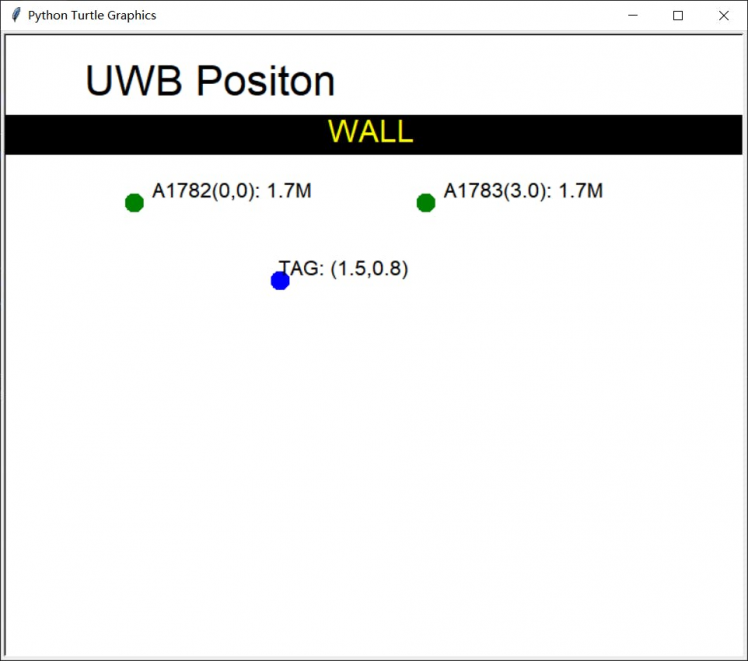
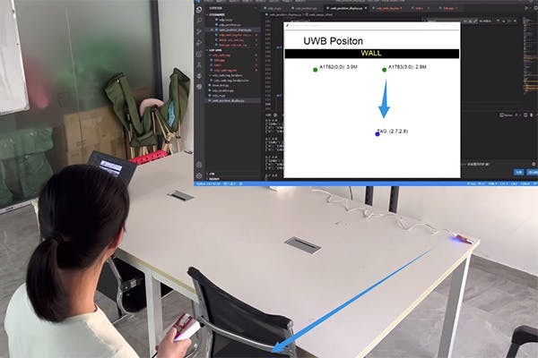
And run the Python program on the PC side. Attach the UWB tag to the power bank and wait for it to connect to the WiFi in the room. After the Tag is connected to the PC, the graphical interface pops up.
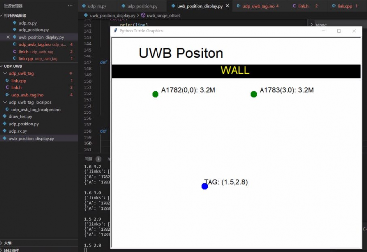
Move the UWB tag around, the tag position can be real-time monitored at the PC:

Code
Credits
Makerfabs01
Makerfabs, Turnkey PCB Assemblies | Small Batch PCBA Prototyping | IoT Hardware Engineering.
Related products


Leave your feedback...