
Eodbot With Camera Controlled With Tactigon Skin
Made by The Tactigon / Games & Gaming / Robotics / Wearables
About the project
We wanted to combine the mobility of a tracked rover with the versatility of a robotic arm into a single device that reminds an EOD bot.
Project info
Difficulty: Moderate
Platforms: Adafruit, Arduino, NodeMCU, Raspberry Pi
Estimated time: 4 days
License: GNU General Public License, version 3 or later (GPL3+)
Items used in this project
Hardware components


View all
Story
Introduction
Hello! We made this project to showcase how you can use 2 Tactigon Skin to control a complex device such as an EODbot (Explosive Ordnance Disposal Robot). The robot itself consists of a tracked rover and a robotic arm and camera.
These type of devices are used in dangerous zones like minefields and in counterterrorism operations to check if in buildings and vehicles there are explosive devices. Every day they're used in trainings for bomb squad staff to practice defuse and destruction of explosive devices. In fictional universes, like the Battlefield franchise, the EODbot is a popular gadget used to destroy vehicles and objects to free up the road.
Scene from the gameplayHardware Architecture
The architecture of this project can be separated into 2 main blocks: the data acquisition and sending block and the execution block.
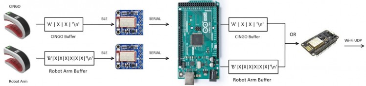
Data acquisition and sending
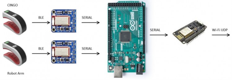
In this section we have 2 Tactigon Skin that gather information about the movements of the hands and send those data to a central hub (the Arduino Mega) with dedicated BLE modules. Once the data is received by the Mega an integrity check is done to ensure that the data packet follows the desired organization pattern. If so the NodeMcu, with its ESP8266 onboard module, is used to send the informations over to a RPi with the UDP protocol (see our previous project for that: BLE-WiFi Range Extender).
Execution block
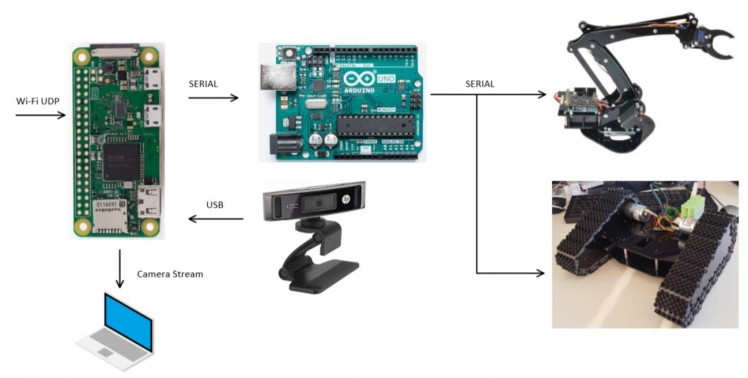
Here is shown all the hardware that is mounted into the EODbot itself. The Raspberry Pi Zero is in AP mode and receives the UDP packets using a python script. Then, using the onboard GPIO UART, we forward the data over to the main brain of the rover, the Arduino Uno, to control both the Robotic Arm and CINGO. We also have a USB webcam plugged in to the Pi that allows us to have a video feed of what the robot sees. The user can access it using a C# interface.
Software Architecture
The software section of the project is pretty straight forward except for some little tricks to save some hardware and hassle in the coding part.
Data acquisition and sending
CINGO
The following snippet of code shows how the buffer is declared and how the data is gaheterd and packed up for the tracked rover's Tactigon Skin:
char buffData[4]; //buffer declaration
buffData[0] = 'A'; //discriminator char to know if the buffer is cingo's data
buffData[3] = 'n'; //new line char to know when buffer ends
//stuff
//...
//sx and dx are computed data based on the angles detected(see full code).
//This gives speed control over the rover
buffData[1] = sx;
buffData[2] = dx;
bleManager.writeToPeripheral((unsigned char *)buffData, 4);
The function bleManager.writeToPeripheral((unsigned char*)buffData,4) is responsible for sending the buffer to the assigned BLE module. We specify that the buffer must be sent as an unsigned char and the buffer length is 4 (as previously declared).
Robot Arm
Here you can see the robot arm's counterpart of the code above:
char bleBuff[32]; //buffer declaration
qData = qMeter.getQs(); //get quaternions data

//shoulder
if(abs(radToDeg(qData.pitch)) < 60)
 shoulderHandling(qData.roll);
//base
baseHandling(qData.yaw);
if(gNippleWrist == 0){
    //gripper (open/close)
    nippleHandling(qData.pitch * 1.5);
}
else{
    //wrist rotation
    wristHandling(qData.pitch * 1.5);
}
//prepare buffer for ble
sprintf(bleBuff, "B%d,%d,%d,%d,%d %dn", a1_shoulder, a2_elbow, a3_wrist, a4_nipper, a5_base, crc);
bleManager.writeToPeripheral((unsigned char *)bleBuff, strlen(bleBuff));
As you can see from the code every articulation of the robotic arm is handled by its special function, given the correct angle to analyze. We've added a discriminatory char, 'B', to know that the buffer is the robot arm's one and not the cingo one.
Execution block
As previously said some trickery is involved so that we can use as much of the available device capabilities avoiding the use of additional hardware for the serial communication. The Raspberry Pi Zero has 2 serial ports, ttyS0 and the much more capable ttyAMA0, but we can map only one of them to the GPIO...what a bummer. This technical detail prevent us to use separate serial ports for the robot arm and the rover. We can get around this problem with the help of the Arduino Uno.
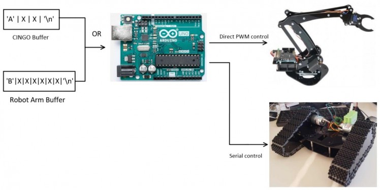
The Arduino Uno receives packet of data and, thanks to the discriminatory char that we've put in the buffers of both cingo's and robot arm's Tactigon Skin we can decide if to pass the data to the movemets function for the robot arm or simply forward it to the serial motor driver of CINGO.
To decide we use the following snippet of code:
int ARMmatch = 0;
inBuff.toCharArray(buff, sizeof(buff));
ARMmatch = sscanf(buff, "B%d,%d,%d,%d,%d %d", &a1, &a2, &a3, &relYaw_3, &yaw, &cks);
if (ARMmatch == 6){
    //call functions for robot arm movement
}
else{
    Serial.write(buff[1]);
    Serial.write(buff[2]);
}
We use the function sscanf to check if the received buffer is coherent to the structure of the robot arm instruction buffer. If so the movements handle functions will take care of that otherwise it means that we have received instructions for CINGO to move. Remembering that the buffer has at the beginning and at the end fixed chars used to distinguish it, only the data at indexes 1 and 2 of the buffer are valid instructions for CINGO.
Camera Feed
The camera feed have been achieved using a piece of software called Motion, a very popular solution for Raspberry Pi users since it is very easy to configure and customize supporting a wide range of camera devices.
We've found that the following settings gives us the best stream quality, both in the resolution and framerate, when the rover is moving:
- framerate = 30
- minimum_frame_time = 0
- output_pictures = off
- stream_quality = 50
- stream_maxrate = 100
In order to start Motion at every boot up sequence of the RPi we have to add the following to the rc.local file, usually located at /etc/rc.local (before exit 0):
sudo motion start
Now that we have a working camera feed via a webpage (local_IP:8081) and a configuration panel (local_IP:8080) we have to find a more elegant and functional way to access it... and C# to the rescue!
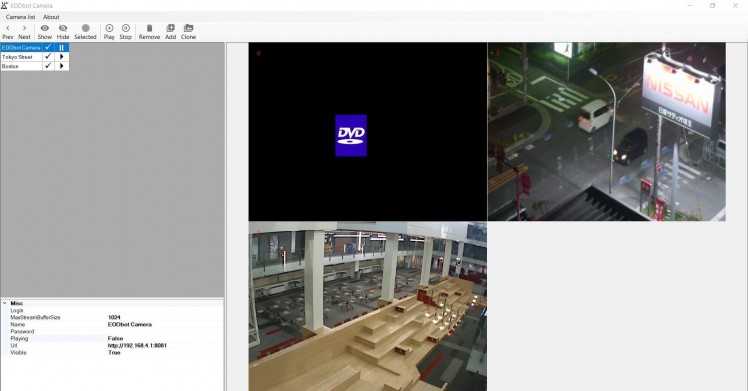
C# EODbot Camera Viewer
Main form of the C# applicationThe above is a little example of how the camera feed can be accessed with the application. You can save many camera feeds using the app and access only the ones that interests you. The configurations and camera list are saved locally in a file. To import a camera feed simply click on "Add" and then provide the necessary data: URL (or direct IP) of the camera, password if needed and the maximum streaming buffer size. You can also choose if the feed is visible in the app or hidden and control the playback. If the feed is not accessible or the camera is down for any reasons, you'll see the classic DVD logo (moment of nostalgia).
 No feed on EODbot Camera
Conclusions
The EODbot in action!With this project you now have an idea of how you can use more than one Tactigon Skin at the time for complex projects. We've used some of the knowledge of a prevoious project (Extender, CINGO and Robotic Arm) and applied it to enable the control of the rover over long distance. You can further customize this project with the use of alternative end-effectors for the robotic arm, such as a suction gripper.
Video feed of EODbot in actionWe've also showed how you can integrate remote camera feed to have a view of what your project is doing. A possible improvement could be the use of an IR capable camera to enable the use of it even in darker enviroment.
Code
Credits
The Tactigon
The Tactigon is a brand of Next Industries Milano. Next Industries is a born of a passion to develop devices and sensors fit for Iot Technology. Our team is made of incredible experts in movement detection for big structural monitoring systems, software development and wearable device.
Related products


Leave your feedback...