
Diy 8x32 Led Matrix Smart Clock With Awtrix 3.0

About the project
DIY 8×32 ESP32 LED Matrix Smart Clock with AWTRIX Light—fully customizable desk display for time, sensors, and cool animations 😊
Project info
Difficulty: Moderate
Estimated time: 5 hours
License: GNU General Public License, version 3 or later (GPL3+)
Items used in this project
Hardware components

Software apps and online services
Story
Following the old maker rule: why buy something when I can build it myself for twice the effort 😄
Also, to be honest, I saw a YouTuber do something similar a while ago and thought, “yeah… I want that on my shelf too. I wanted a small LED matrix behind my desk that could show my subscriber count, time, and other info.
You can buy ready-made displays like this for around €60. The goal here was simple: stay well below that and still get something cool and customizable. That also meant using my 3D printer for the case.
So this is how I built my own LED matrix smart clock using AWTRIX Light.
Supplies1 / 8

I tried to keep this simple and cheap. This is what I used:
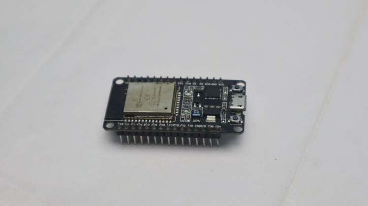
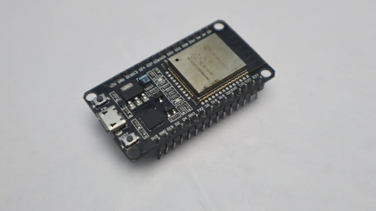
- ESP32 Dev Board
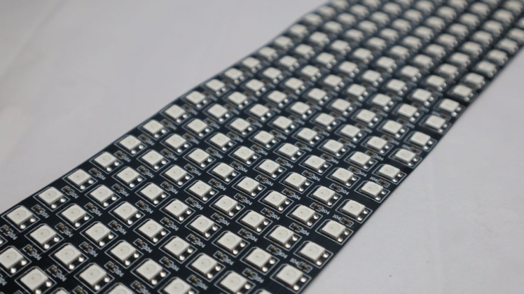
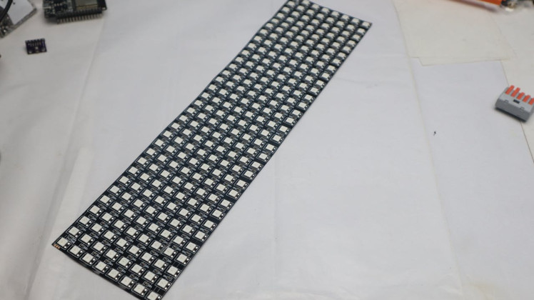
- 8×32 WS2812B LED matrix display
- 5V power adapter
- Some jumper wires
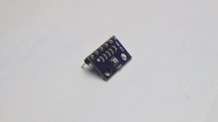
- BMP280 sensor (optional, for temperature/pressure)
- 3D printed case
- USB cable and basic tools
You might already have some of these parts lying around. Download the below attached STL file and 3D print it.
Sponsored by NextPCB
This project was successfully completed with the support of NextPCB, a reliable multilayer PCB manufacturer. With over 15 years of experience in PCB fabrication and assembly, NextPCB offers high-quality and dependable PCB solutions for makers and professionals worldwide.
You can order high-quality PCBs starting at $1.9, and multilayer PCBs starting at $6.9:
https://www.nextpcb.com/pcb-quote
Get free PCB assembly for up to 5 boards:
https://www.nextpcb.com/pcb-assembly-quote
You can also check your designs using their free online DFM & Gerber viewer:
https://www.nextpcb.com/free-online-gerber-viewer.html
Step 1: Choosing the Parts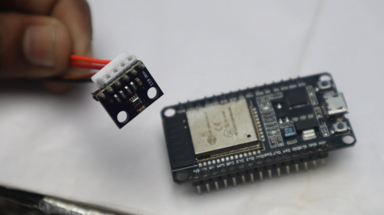
About €5 went into the ESP32.
It’s important to use an ESP32 because AWTRIX Light only works properly with it.
For the display, I went with an 8×32 LED matrix. Earlier I considered using four 8×8 modules, but in the end this was cleaner and easier.
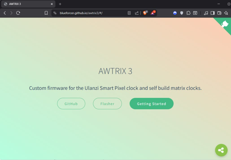
Flashing AWTRIX 3 on the ESP32The next step was the software part.
To flash AWTRIX Light, you need Google Chrome or any other Chromium-based browser like Edge.
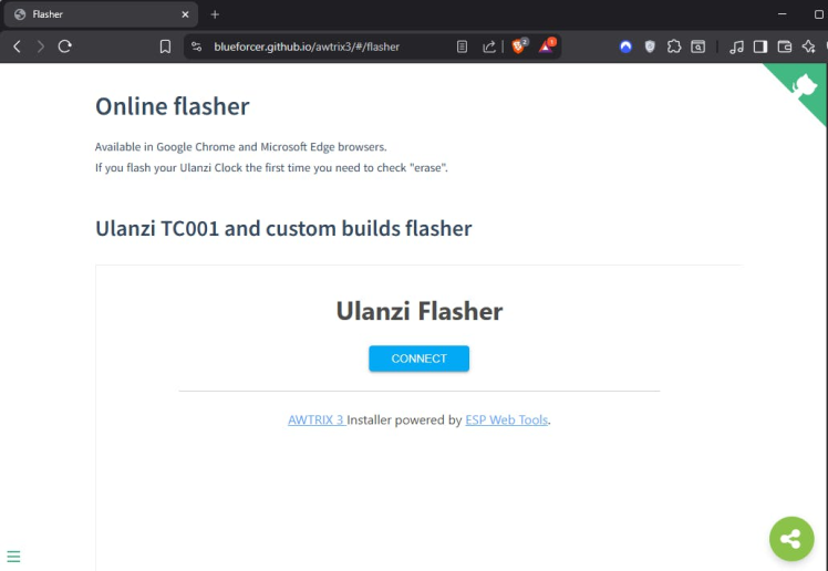
I connected the ESP32 to my PC using a USB cable and opened the AWTRIX online flasherpage.
After clicking CONNECT, a list of serial ports appeared. On Windows, this usually shows up as a COM port. On Linux, it’s typically something like ttyUSB0.
1 / 2
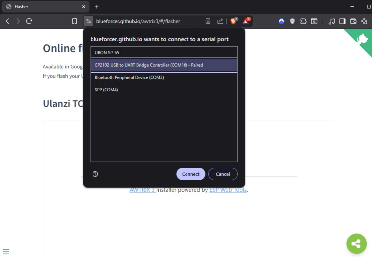
If you’re not sure which one is correct, unplug the ESP32 and plug it back in—whatever port appears again is the right one.
1 / 6
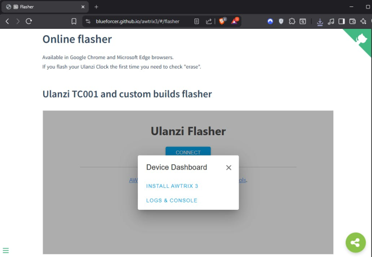
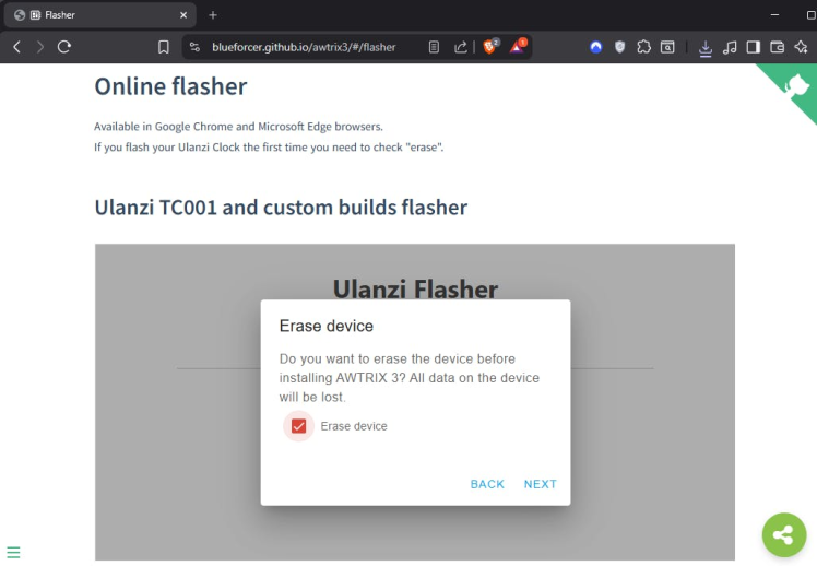
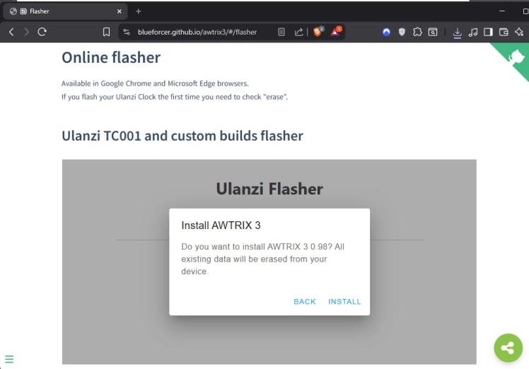
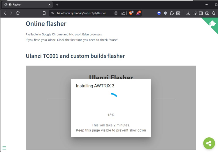
Once connected, I clicked INSTALL AWTRIX 3. Since this was the first time flashing the board, make sure Erase device was checked, then clicked Next and Install.
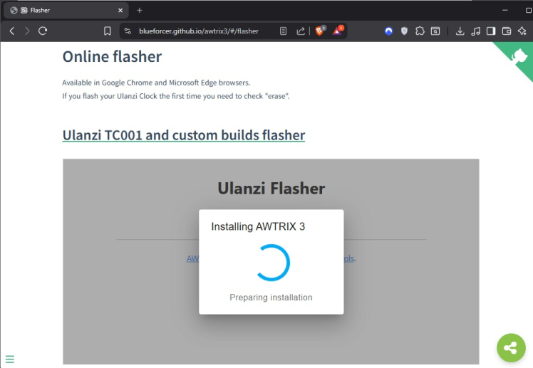
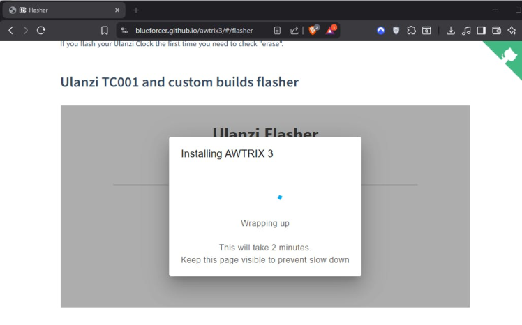
The flashing process takes about two minutes. Keep the browser tab open and don’t disconnect the ESP32. Sometimes it looks like it’s stuck for a moment, but that’s normal. When the process finishes, you’ll see Installation complete.
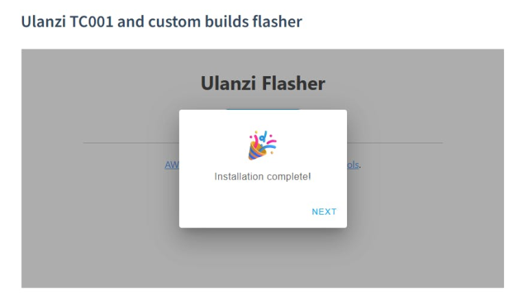
The ESP32 reboots automatically, and AWTRIX is now installed and ready for Wi-Fi setup in the next step.
Quick Wiring Test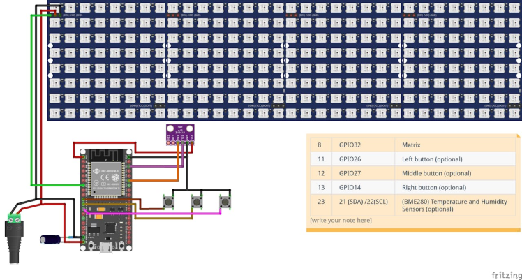
Before putting anything into the 3D printed case, I did a full test on a breadboard. This really helps because if something is wired wrong, you can fix it easily without opening the case again and again.
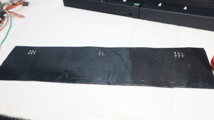
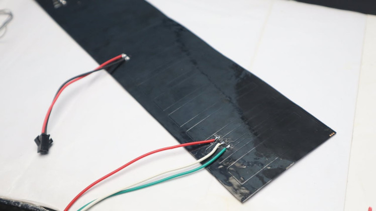
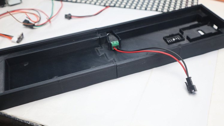
First, I soldered a JST-SM 3-pin connector to the LED matrix for power and data. I also soldered the power cable so it’s solid and doesn’t come loose later.
1 / 3

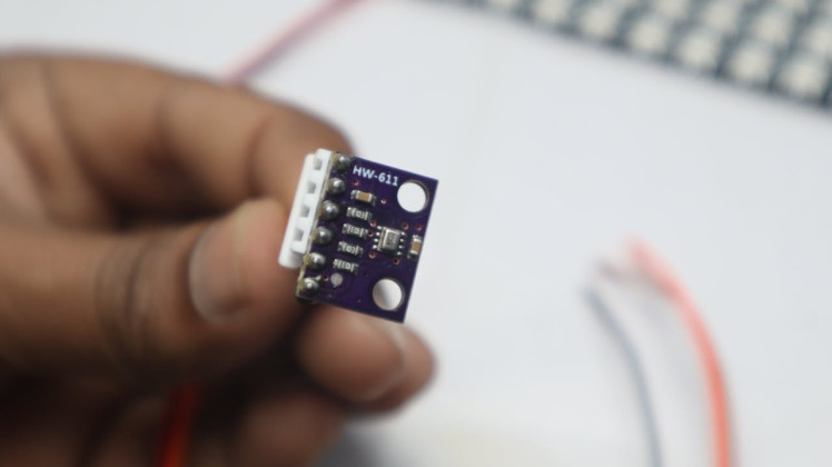
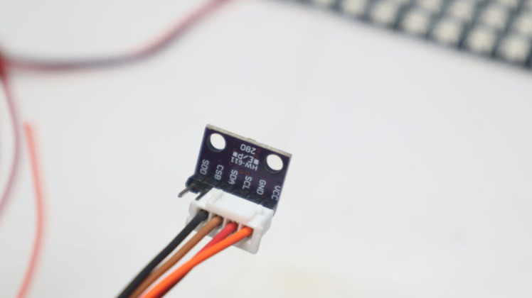
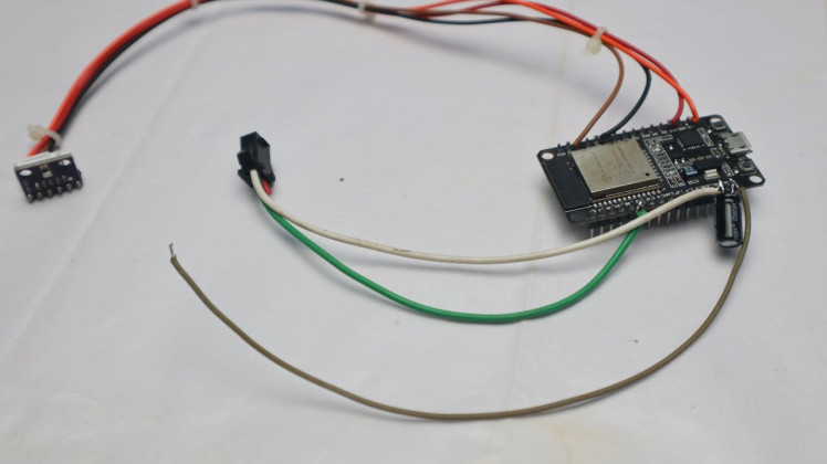
For the BMP280 sensor, I used a 4-pin jumper cable so it can plug directly into the ESP32.
1 / 2
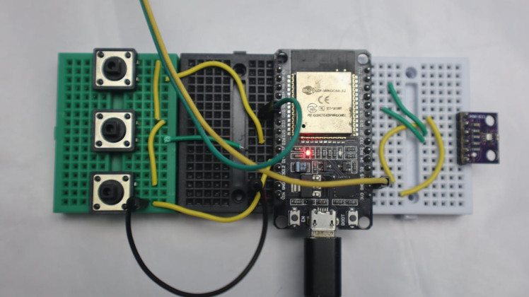
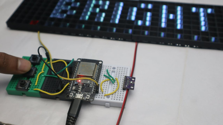
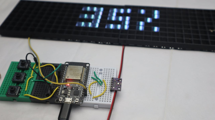
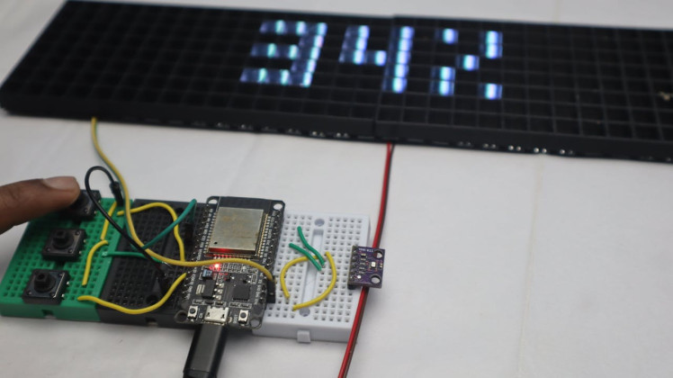
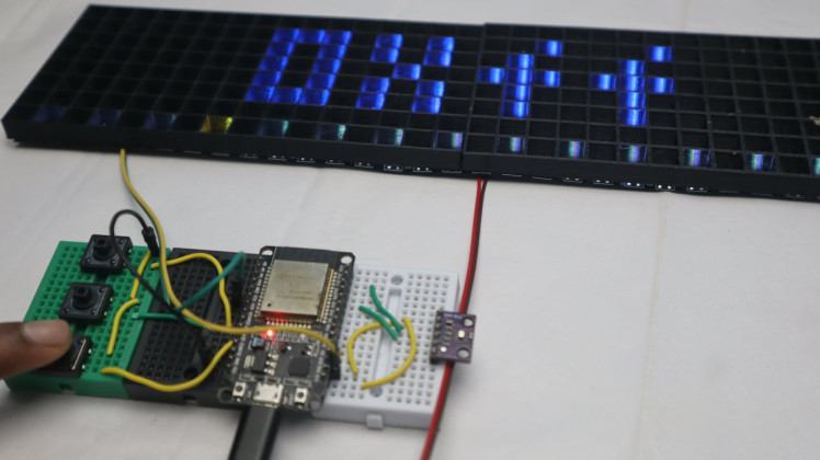
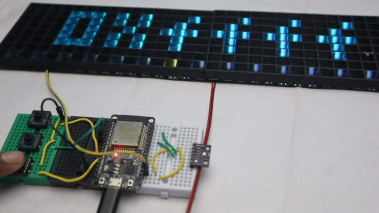
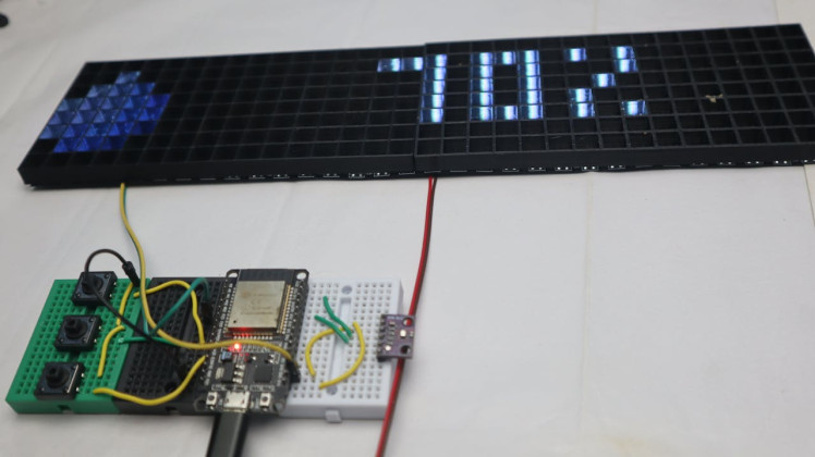
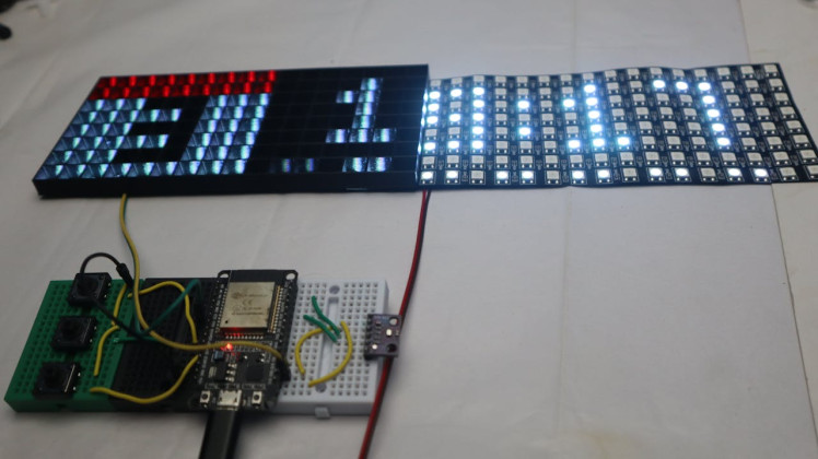
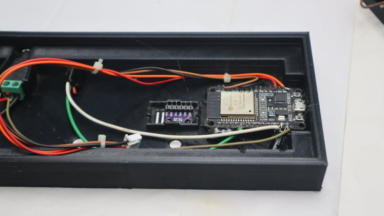
The LED matrix wiring is very simple. It only needs 5V, GND, and a DATA line. The power line goes to both the ESP32 and the LED matrix, and the data line is connected to GPIO 32, which is the pin recommended by AWTRIX.
In the photo here, you can see my temporary wiring and soldering. It’s definitely not the prettiest setup, but it’s strong enough for testing, which is all I needed at this stage.
1 / 4
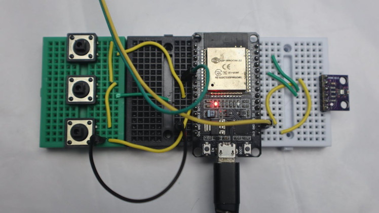
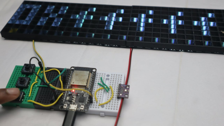
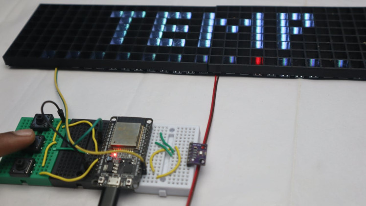
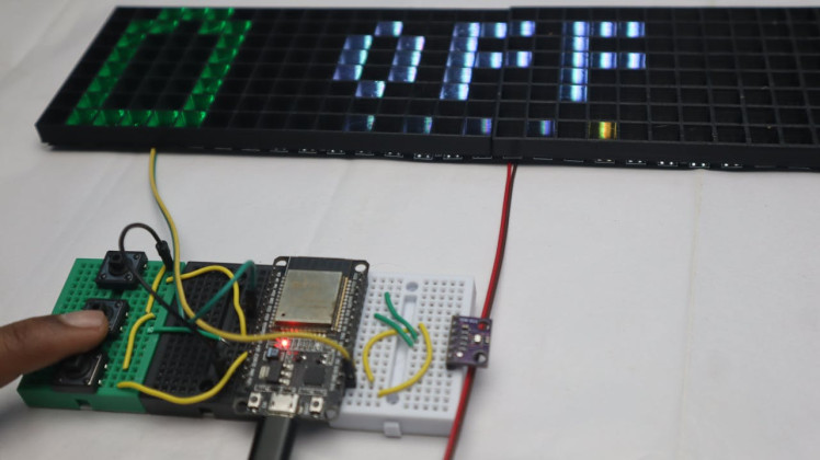
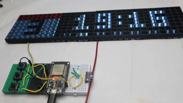
I also connected three buttons for testing. AWTRIX comes with a few default apps like time, date, battery, temperature, and animations. The buttons make it much easier to change settings and navigate the menu.
These are the pins I used for the buttons:
- GPIO26 – left button
- GPIO27 – middle button (inverted)
- GPIO14 – right button
For temperature readings, I connected a BMP280 sensor using I²C:
- GPIO21 – SDA
- GPIO22 – SCL
AWTRIX also supports other sensors like BME280, HTU21D, and SHT31, so you can use whatever you already have.
To keep the power stable, I added a 470µF, 16V capacitor between VIN and GND on the ESP32. This helps smooth out voltage drops, especially when the LED matrix draws more current.
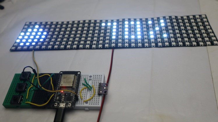
Once everything was connected on the breadboard, I powered the setup using an external 5V, 3A power adapter. Since AWTRIX was already flashed earlier, the ESP32 was now ready for setup and testing.
Wi-Fi Setup and AWTRIX Configuration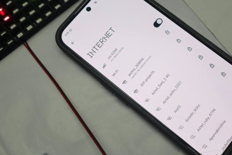
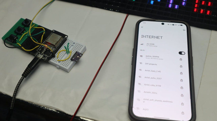
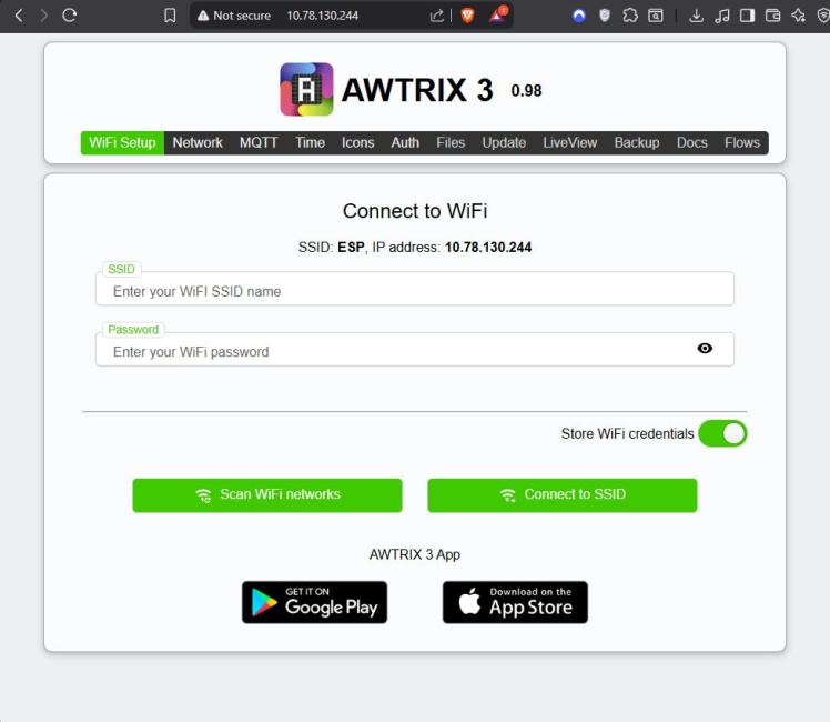
After powering it on, the ESP32 starts its own Wi-Fi and web server automatically. I connected my phone to the AWTRIX Wi-Fi network. The default password is 12345678.
Once connected, it opens a setup page where you enter your home Wi-Fi details. One important thing to remember: the ESP32 only works on 2.4 GHz Wi-Fi, so make sure you select that band.
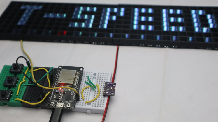
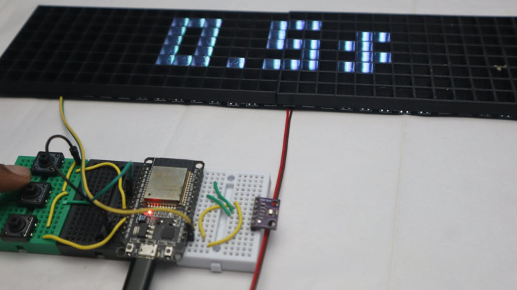
After the ESP32 connects to your Wi-Fi, the display shows the AWTRIX logo along with the date and time. At first, the time was wrong because the default timezone didn’t match my location.
1 / 6
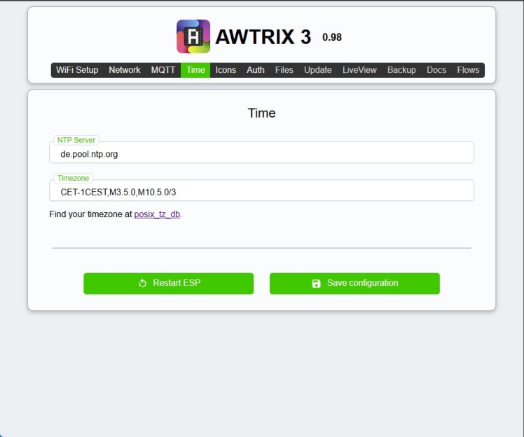
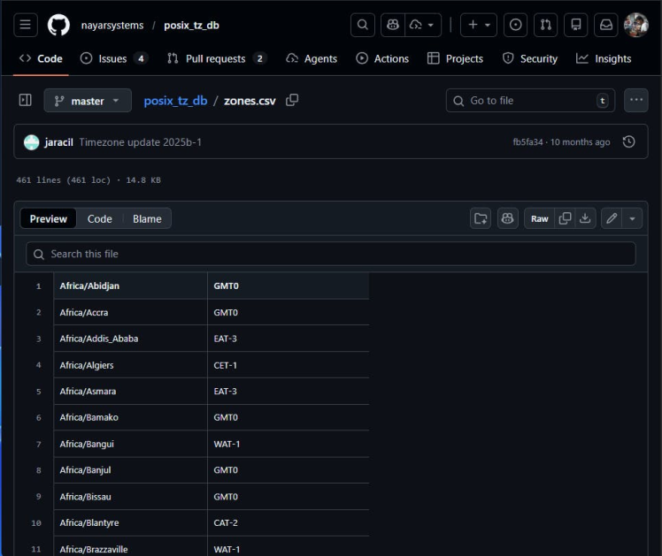
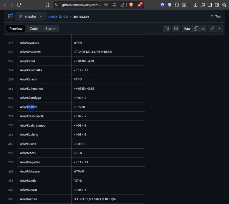
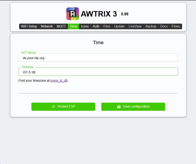
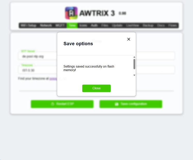
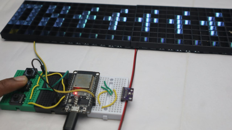
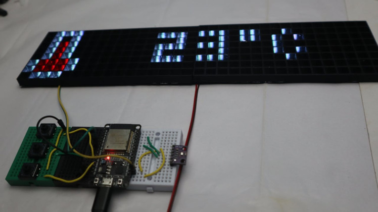
The IP address of the ESP32 is shown directly on the LED matrix. I typed that IP into my browser to open the AWTRIX web dashboard. From there, I changed the timezone (I’m in India, so I set GMT +5:30), saved it, and the time updated correctly.
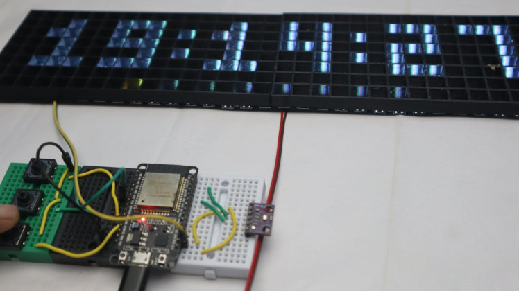
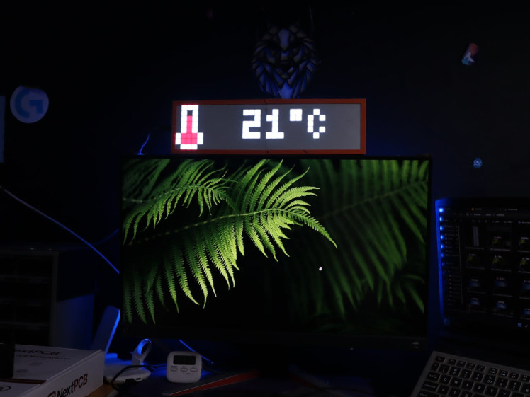
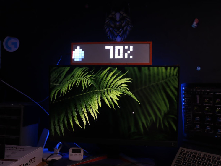
Adjusting Settings and ButtonsAt this point, everything was working. The display showed time, date, temperature, humidity, and battery status. Since I’m using a power adapter, I didn’t need the battery icon, so I disabled it in the settings.
1 / 27
Most settings can also be changed directly using the buttons on the clock. AWTRIX has a built-in on-screen menu:
- Press and hold the middle button for 2 seconds to open the menu.
- Use the left and right buttons to navigate.
- Press the middle button to select.
- Hold the middle button again for 2 seconds to save and exit.
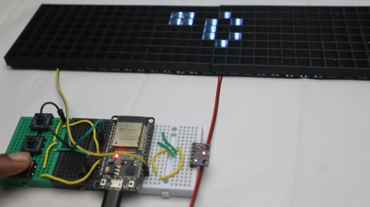
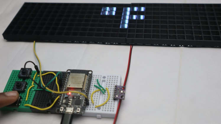
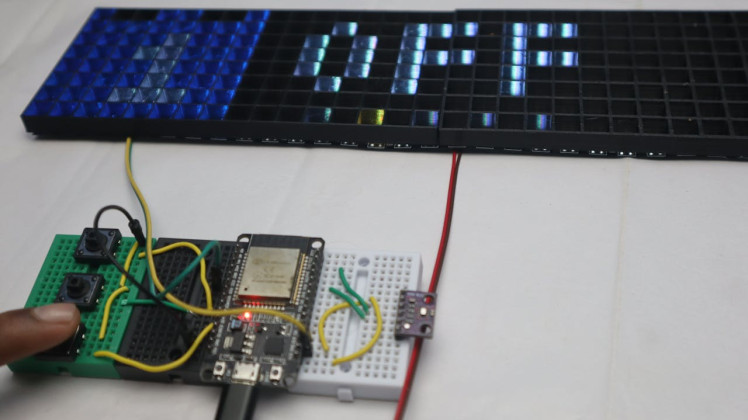
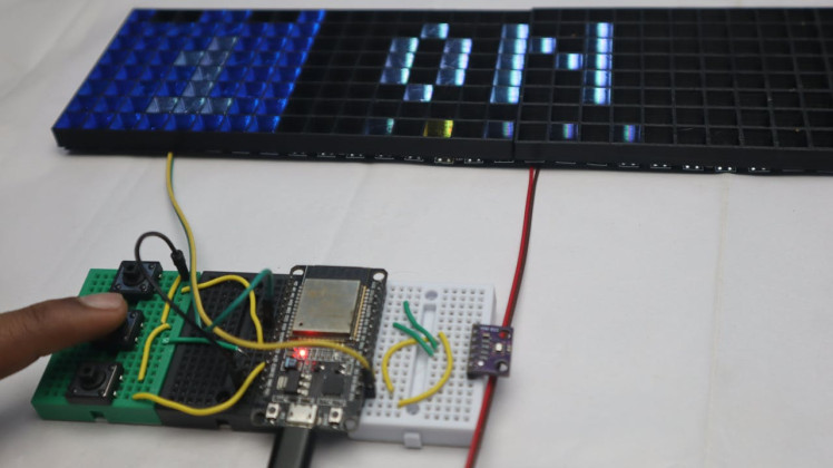
You can also turn the display on or off by double-pressing the middle button when you’re not in the menu.
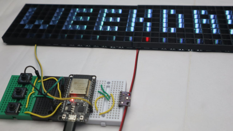
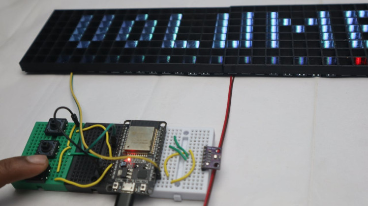
I’ll attach photos showing the menu in action, including brightness, colors, transition speed, and enabling or disabling icons. After setting everything the way I wanted, the matrix was ready to be mounted into the 3D printed case.
If anything doesn’t work the first time, don’t worry—most issues are just wiring or Wi-Fi related. Feel free to comment if you get stuck.
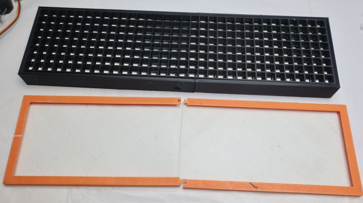
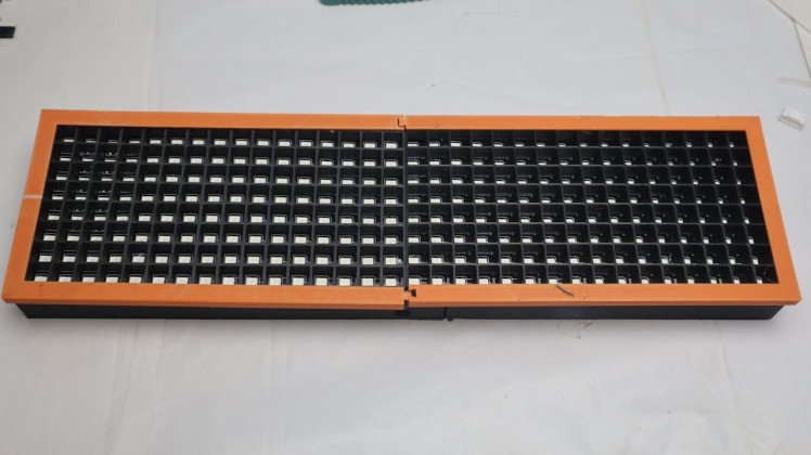
3D Printing the 8×32 LED Matrix Frame1 / 4


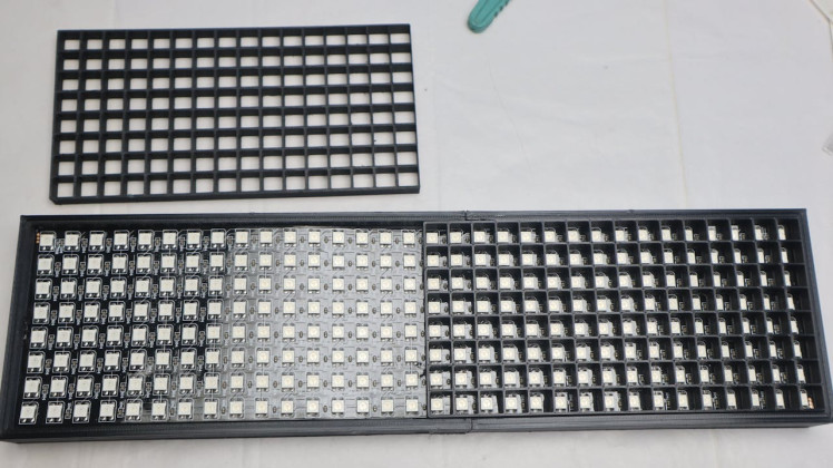
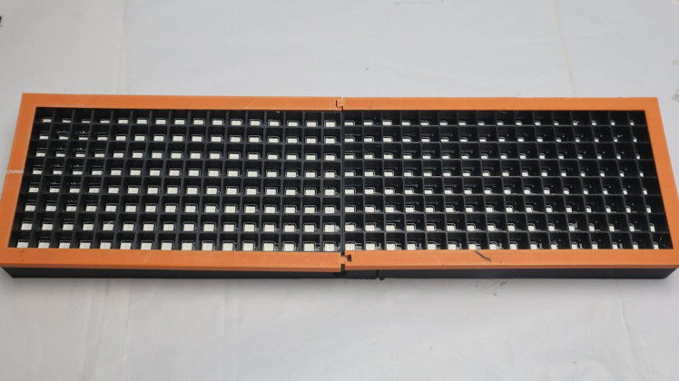
For the case, I used a ready-made 8×32 LED matrix frame design. One thing I really liked about it is that it doesn’t require glue, tape, or screws. Everything is designed to snap together, which makes assembly much easier.
The frame keeps the USB port accessible, and you can use it either on a desk or mount it on the wall. It also has snap-fit spots for the ESP32, microphone modules, and the DC power connector. There’s even a version without sockets if you want to keep it super simple.
One small note: even though it’s a snap-fit design, I recommend gluing the two front frame pieces together. That part just feels more solid that way.
I want to say thanks to the enclosure designer FractalNoise — it’s a really nice design. There are plenty of similar 8×32 matrix enclosures online, so feel free to use any design that fits your display and setup.
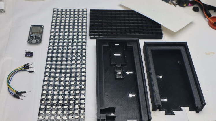
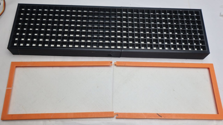
Printing the PartsThese are the parts I printed:
- 2× Front (split)
- 2× Diffuser (split)
- 1× Back Left (split)
- 1× Back Right (split)
For the diffuser screens, I followed specific print settings to get a horizontal “scanline” effect on the display. It gives the LEDs a nicer pixel look instead of looking too harsh.
These are the slicer settings I used for the diffuser:
- Top/Bottom surface pattern: Aligned Rectilinear
- Internal solid infill pattern: Aligned Rectilinear
- Sparse infill pattern: Aligned Rectilinear
- Infill direction: 0°
If you’re printing the diffuser in white filament, it matters which build plate you use. A textured plate makes the light more scattered and a bit dimmer. A smooth plate gives much better results. For clear filament, a textured plate actually works really well.
My prints aren’t perfect because I’m using an older 3D printer, so don’t stress if yours don’t come out flawless either. It still works just fine.
Assembly in the EnclosureAfter printing everything, I went back to the electronics. First, I soldered the wires to the ESP32 according to the same pinout I used earlier during testing.
1 / 11
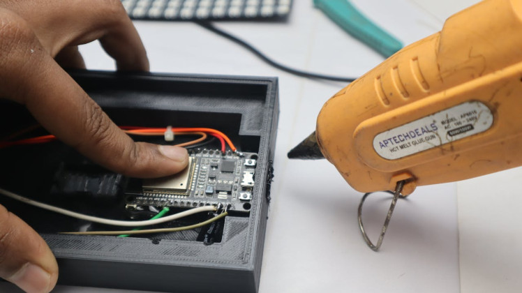
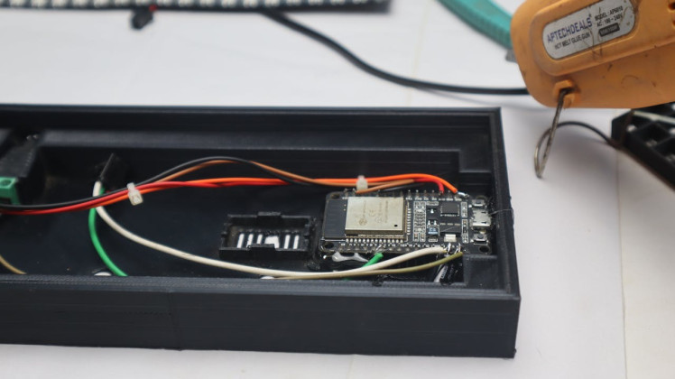
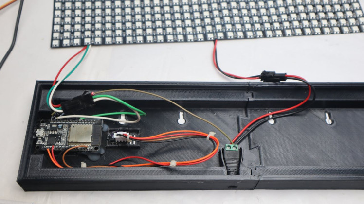

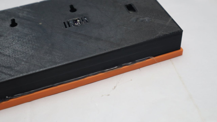
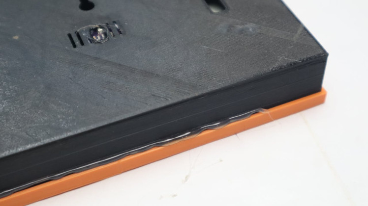
Once that was done, I started placing all the parts into the printed enclosure. The LED matrix goes in first, followed by the diffuser and front frame. Then I placed the ESP32, sensor, and power connector.
Some parts didn’t fit as tightly as I wanted, so I used a bit of hot glue to secure the ESP32 and the sensor. This isn’t mandatory, but it helps keep everything in place, especially if you plan to move it around.
After everything was in place, I closed the back cover, snapped the diffuser and front frame on, and powered it up one last time.
At this point, the matrix was fully assembled and ready to use.
Final Result and Conclusion1 / 7
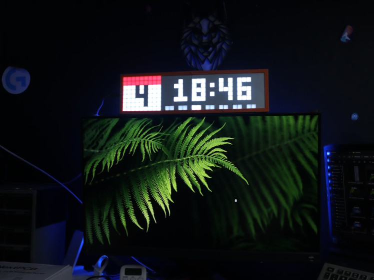
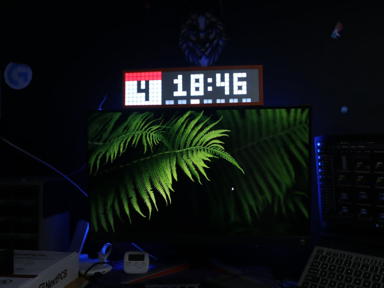
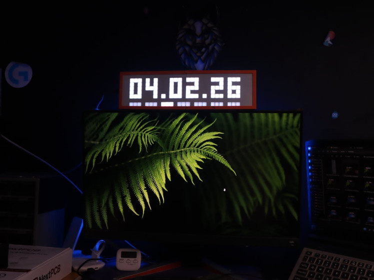
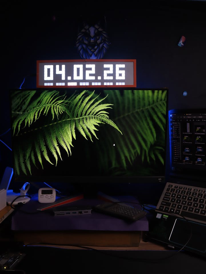
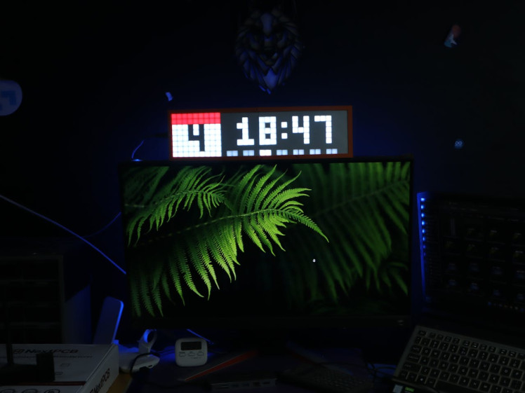
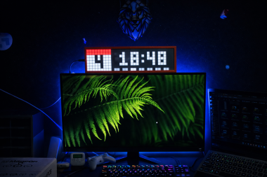
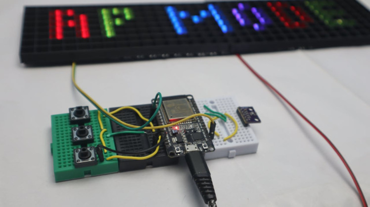
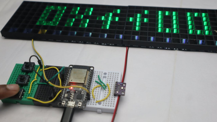
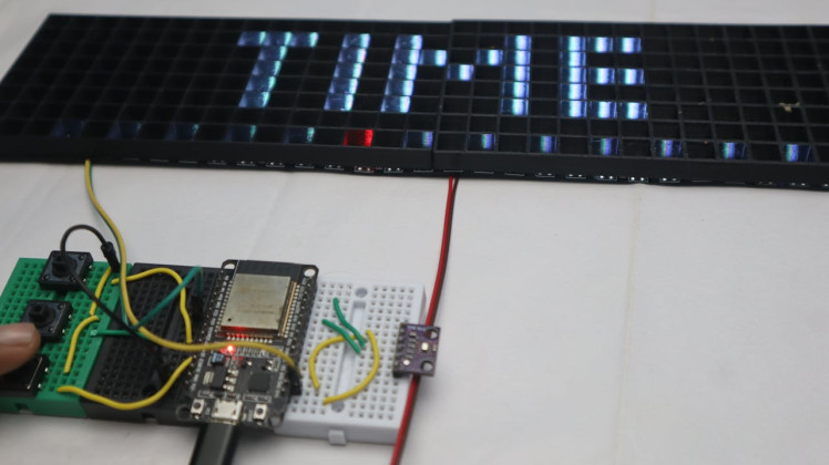
After everything was assembled and powered on, the matrix was finally ready. I tried it both ways—sitting on my desk and mounted on the wall—and it works great in both positions.
On the desk, it’s perfect as a small smart clock. It’s easy to read from a distance, and the brightness is adjustable so it’s not annoying at night. Mounted on the wall, it looks more like a proper display panel and blends in nicely with the setup behind my desk.
In the photos here, you can see how it looks. The 8×32 size is just right—not too big, not too small—and the diffuser gives it a clean pixel look without being too harsh on the eyes.
If you build one yourself or change something, feel free to share it in the comments. Happy making 🙂
Leave your feedback...