
Digital Arduino Voltmeter

About the project
A Voltmeter or a Voltage Meter is a measuring instrument that is used for measuring voltage.
Project info
Difficulty: Moderate
Platforms: Arduino
Estimated time: 1 hour
License: GNU General Public License, version 3 or later (GPL3+)
Items used in this project
Hardware components


Story
To overcome the drawbacks of analog voltmeters, Digital Voltmeters are presented. Rather than only scaling and pointing to show a measured voltage like as analog voltmeter, digital voltmeters directly display the measured voltage on the digital display.
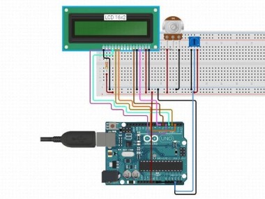
Circuit Design
Pin 1 and Pin 2 (Vss and Vdd) of the LCD power supply are the pins for display. They are attached to ground and +5V supply respectively. Pin 3 (Vee) of the LCD is connected to the wiper terminal of the 10KΩ POT and the other terminals of the POT are connected to +5V supply and ground respectively.
The next 3 pins of the LCD are control pins. Pin 4 and Pin 6 of the LCD are attached to digital input/output pins 2 and 3 of Arduino respectively. Pin 5 (RW) of the LCD is attached to the ground.
Pin 15 (LED+) of the LCD is connected to +5V supply via a current limiting resistor of 220Ω. Pin 16 (LED-) of the LCD is attached to the ground.
The output of the voltage divider circuit consisting of 100KΩ resistor and 10KΩ resistor is attached to the analog input pin A0 of the Arduino UNO with another end of the 100KΩ resistor attached to the voltage to be calculated and the other end of the 10KΩ resistor attached to the ground.
Working
In a digital voltmeter, the voltages to be estimated, which are in analog form, are switched to digital form with the help of Analog to Digital Converters (ADC). Hence, the ADC specialty of the Arduino UNO is used in this project.
The span of voltages for Arduino Uno's analog input is 0V to 5V. Hence, in order to improve this range, a voltage divider circuit need to be used.
With the help of the voltage divider circuit, the input voltage being calculated is taken down to the range of Arduino UNOs analog input.
Arduino Digital Voltmeter

IoT Training in Pune offers you a thorough view of all IoT applications in various industries.
Code
Credits
Related products


Leave your feedback...