
Digital Ammeter Using Arduino

Made by hIOTron / Home Automation / IoT
About the project
In this project, we are going to measure the current using ohm's law.
Project info
Difficulty: Moderate
Platforms: Arduino
Estimated time: 1 hour
License: GNU General Public License, version 3 or later (GPL3+)
Items used in this project
Hardware components


Story
About the Project:
As we all are aware of ohm's law, which states that
V=IR
Where V= voltage in volt (v)
I= Current in Ampere (A)
R= Resistance in ohm (Ω)
To find I we have to use
I= V/R
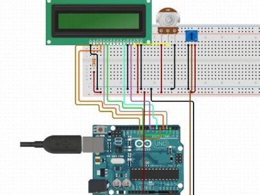
This Ammeter circuit contains a resistor and LED as a load. The resistor is attached in series to the LED that current flows via the load and voltage drops are discovered from the resistor.
In the ADC of Arduino that modifies the voltage into 10-bit resolution numbers from 0-1023. So we require to modify it in voltage value bu utilizing the programming.
The value of voltage from the ADC of Arduino is ranged between 0-1023 and the reference voltage is ranges between 0-5v. From the above voltage value and by dividing it with 22 ohm we can calculate current. Here we have utilized the value of 22ohm resistor as current sensor.
IoT Training will give you a thorough view of such IoT Projects.
Code
Credits
Related products


Leave your feedback...