
Currus Futuristicus

Made by paced / Artificial intelligence / Automotive / Robotics / Sensors / Vehicles
About the project
We are participating in the NXP Cup, it’s a competition where we build and program an autonomous robotic car. We want to demonstrate that anybody with determination can learn to code, with the majority of the team having never coded before. We would like your support to demonstrate that anybody can do it.
Project info
Difficulty: Difficult
Estimated time: 4 months
License: GNU General Public License, version 3 or later (GPL3+)
Items used in this project
Hardware components

View all
Software apps and online services
Hand tools and fabrication machines
Story
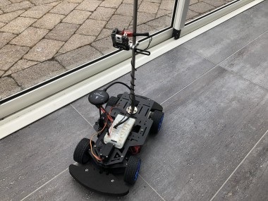
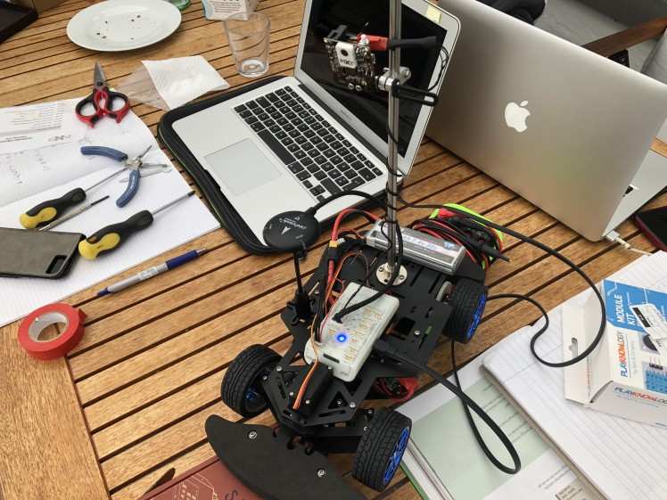
We are going to build a robot for the NXP Cup. The robot should be able to complete all four tasks. We are focusing primarily on the speed and obstacle avoidance tasks. For the speed task, the biggest challenge is to keep the car within the lines and prevent it from going to fast that it overshoots a turn. We will use a P ixy cam 2 for our camera input as it has built in line recognition. We will develop a program so that the car stays in the middle of two lines except at corners where it will optimise it’s position for max cornering speed. To solve the obstacle avoidance challenge, we will have a LIDAR to map the surroundings and detect obstacles in the room and detect slopes. We will program the robot to avoid the obstacle prioritising safety over speed whilst staying within the lines. Then we will tell the robot to turn another way, but still stay between the lines. To determine the distance to the obstacle, we might use an ultrasonic sensor for increased accuracy.

Assembly
Avoid Short Circuit
Since the chassis is mate of metal we wanted to reduce the risk for a short circuit by covering the yellow connector with tape.

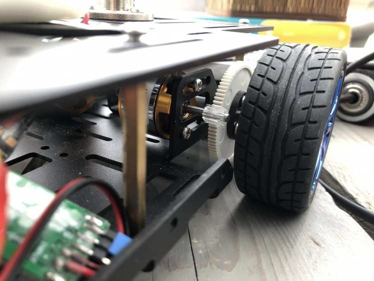
Gear Does Not Fit
Since one of the gears following was too big, we have CADed and laser cut some gears. This will only be a temporary solution as the acrylic wheel gives more resistance to the motor, and it has a higher risk of breaking during the race.
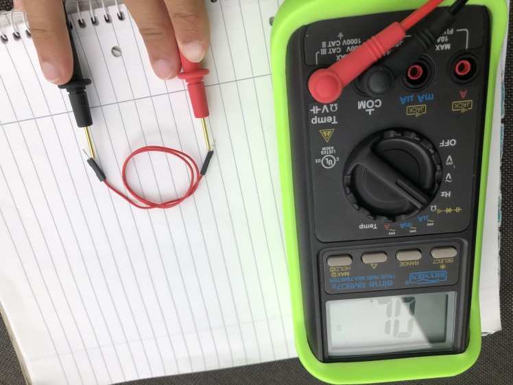
Rewiring of Pixy2 I2C Cable
We had to cut some of the wires on the cable going from the Pixy to the FMU. The wires were resoldered as described on the NXP Cup Known Issues page. It was impossible to see which colored wire (Pixy side) belonged to which pin on the FMU side. To relate the wires and the pins, we ringed the wires with a multimeter (pleas bear with the image being upside down).
Installing the PX4 Toolchain for Mac
To do this, we had to install Homebrew first. Then we followed these instructions.
However, we had some deviations:
We skipped:
brew install px4-simThen, we followed the build instructions link and did the steps "Downloading PX4 Source Code" and "First Build (Using the JMAVSim Simulator)"
Firmware Build and Upload
The firmware is built by opening a terminal, going to Firmware (not case sensitive)
cd Firmwareand building the code.
make nxp_fmuk66-v3If the terminal is complaining about too many open files, say
ulimit -S -n 2048I'm not 100% sure what is means, but it works. A successful build ends with "Creating..."
To upload to the FMU, after a successful build, connect the FMU to the Mac using the USB-C cable. Sometimes the upload is unsuccessful, we have fixed this by restarting the FMU, using the restart button on the side. The upload command is
make nxp_fmuk66-v3 uploadWith my mac, this takes about 30 seconds.
Initial Changes Done in the Source Firmware
Instructions for the changes can be found at the NXP Cup Known Issues page.
First, we had to download the FMU-K66 Project. This folder called "nxpcup" was then dragged from "Downloads" to Firmware > src > examples using Finder. The Firmware folder can be found under Macintosh HD > Users > *your username* . Then, we had to do two changes in the firmware:
Change 1
Go to Firmware > ROMFS > px4fmu_common > init.d > rcS and type "nxpcup start" between the fi on line 8 and fi on line 17. Note that in the actual file, it's located around line 530.
- if ! param compare SYS_PARAM_VER ${PARAM_DEFAULTS_VER}
- then
- echo "Switched to different parameter version. Resetting parameters."
- param set SYS_PARAM_VER ${PARAM_DEFAULTS_VER}
- param set SYS_AUTOCONFIG 2
- param save
- reboot
- fi
- # NXPCup Autostart
- nxpcup start
- #
- # End of autostart.
- #
- fi
- #
- # Unset all script parameters to free RAM.
- #
- unset AUTOCNF
- unset AUX_MODE
Change 2
Go to Firmware > boards > nxp > fmuk66-v3 > default.cmake and add "nxpcup" to EXAMPLES. The EXAMPLES part is located at the bottom of the file. This step is to include the command that is going to start our algorithm by using MAVLink in QGroundControl (QGC).
- work_queue
- EXAMPLES
- fixedwing_control # Tutorial code from https://px4.io/dev/example_fixedwing_control
- hello
- hwtest # Hardware test
- #matlab_csv_serial
- px4_mavlink_debug # Tutorial code from http://dev.px4.io/en/debug/debug_values.html
- px4_simple_app # Tutorial code from http://dev.px4.io/en/apps/hello_sky.html
- rover_steering_control # Rover example app
- uuv_example_app
- work_item
- nxpcup
- )
Change 3
In "nxpcup_start.cpp" under the "nxpcup" folder, we changed line 54 from
- #define TURINGY_BRUSHLESS
to
- #define DFROBOT_BRUSHLESS
Change 4
In "Pixy2I2C_PX4.cpp" line 5, we changed
- I2C("Pixy2_I2C", IRLOCK0_DEVICE_PATH, PX4_I2C_BUS_EXPANSION, IRLOCK_I2C_ADDRESS, 400000)
to
- I2C(0, "PIXY2_I2C", IRLOCK_I2C_BUS, IRLOCK_I2C_ADDRESS, 400000)
Change 5
In "Pixy2I2C_PX4.h" line 24, we changed
- #define IRLOCK_I2C_BUS PX4_I2C_BUS_EXPANSION
to
- #define IRLOCK_I2C_BUS 1
Own Modifications
Wheel Rotation Direction
Due to a mistake in the soldering of one of the motors to the ESC, the wheel is spinning backwards when using the PWM test function in MAVLink. Therefore, we have to do a change in the roverSpeed function. The change will be presented here soon, but the change is essentially replacing a + with a – to make the backward spinning backwards (double backwards = forwards :)
Problems Encountered
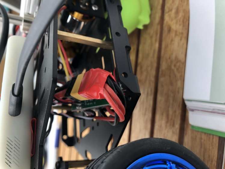
Servo Does not Work
When saying for example 'pwm test -c 1 -p 1100' when the servo is connected to Pin 1, nothing happens. We only hear a constant clicking noise whenever connected to battery. We attempted to disconnect the servo from the UBEC and connect it directly to battery power (see image). But then smoke came out of the servo. We used a 7.4V battery and thought the servo could take 4.8-7.2V. However it appears that the servo only takes 4.8-6.6V. So one should be careful about rewiring as we have done in the image.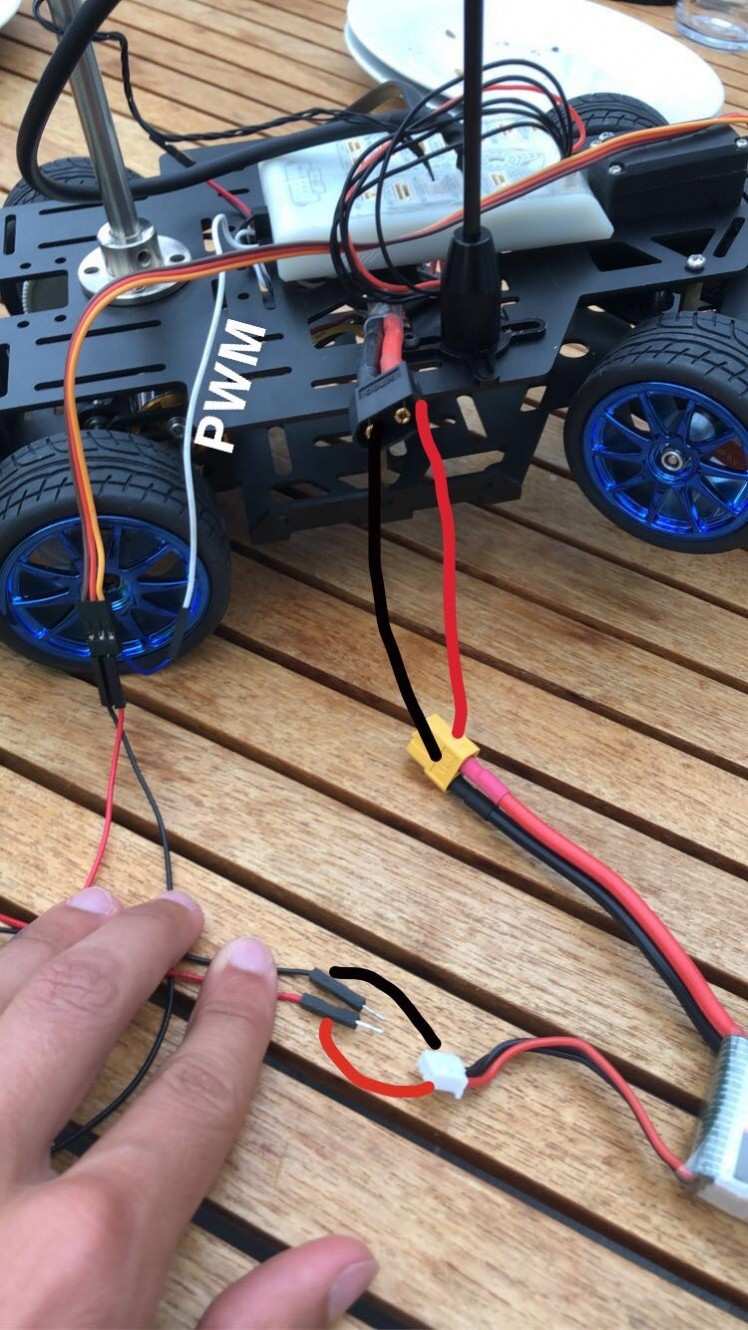
SOLVED! The Example Code Does Not Work
When typing 'nxpcup start' in MAVLink and pressing the safety switch, nothing happens. We leave it for 3 min without any response. The only modification we have done to the code is to add lines in the 'nxpcup_race.cpp' file saying inside the 'roverControl raceTrack(Pixy2 &pixy)' structure.
- control.steer = 0.5;
- control.speed = 0.1;
SOLVED! Concerns with Pixy2 Cam
Firstly, the Pixy cam becomes very hot when the FMU is connected to battery power. Secondly, we cannot understand what the lighting on the Pixy means. When the FMU is only connected to the Mac (and the Pixy is connected to the FMU), its LED lights red. When we then connect to battery power, the red light disappears, and then we can barely see the red, green and blue LEDs light. This light has about half the intensity as if the Pixy was connected only to the Mac via the USB.
SOLVED! GPS LED Does Not Light
Usually, the LED on the FMU and the GPS flash simultaneously. However, the LED on the GPS is no longer flashing. The red safety switch light still flashes as usual.
SOLVED: Error Message When Connecting FMU to QGC
We got this error message when starting QGC:
- EMERGENCY: Mag 0 fail: TIMEOUT!
This was solved by going to Parameters and disable CAL_MAG0_EN and recalibrate the compass. Remember to let the FMU and GPS module always point in the same direction. We did this recalibration after attaching the GPS (using the following mounts, but used only two screws) and the FMU (easily removable double-sided tape) to the chassis.
Testing
So far the ability to test the vehicle has been limited since we have encountered some challenges in making the fundamental functions of the car work. Hence, the only testing we have completed successfully is the motor test, using the command 'pwm test -c 34 -p 1400' in MAVLink to make bot motors turn.
2021 Back at it!
PACEd has signed up for the NXP Cup 2021. Our car is the same, except from that we have changed the servo as the original one was defect. However, the code is new and constantly changing.
2021 Algorithm
Line Following 1
We find the angle of the line we're tracking and convert it to a linear scale. An angle in the range [0, 180] becomes a double in the range [-1.0, 1.0] where +1.0 is a left turn, -1.0 is a right turn, and 0.0 is straight forward. As the 0.0 doesn't necessarily make the car go straight forwards, we introduce a trim variable trying to adjust for this.
We then store the x latest angles (converted to a double [-1, 1]) in an array and use their average to set the servo angle. As per 04.01.21, our x is 10.
2021 Challenges
The Car Turns too Much to the Right
Even with trim corrections. We may need to use a non-linear mapping from the [0, 180] angle to the [-1, 1] steering value.
Battery Status
There's no way of telling whether out battery is fully charged or not.
Ultrasonic Sensor (USS)
The USS doesn't fit into the FMU. There exist adapters, but not yet obtained. Yet, we have not found out how to retrieve the signal from the USS to the FMU. We don't know what C++ commands we must use.
Give/Get Help
If you also participate in NXP Cup 2021 and have faced some challenges you'd like to discuss, don't hesitate to contact us on email or on our Facebook page.
email: uoenxp@gmail.com
Facebook: UoE NXP Cup 2019/20
Credits
Related products


Leave your feedback...