
Control Led Matrix Max7219 With Arduino

Made by Ron / Displays / Home Automation / Notifications / Sensors
About the project
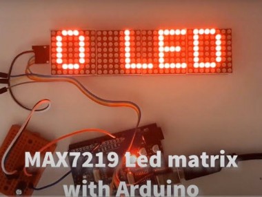
In this tutorial we will learn how to control the MAX7219 Led matrix with Arduino by displaying a simple text.
Project info
Difficulty: Moderate
Estimated time: 1 hour
License: GNU General Public License, version 3 or later (GPL3+)
Items used in this project

Story
In this tutorial we will learn how to control the MAX7219 Led matrix with Arduino by displaying a simple text.
Watch a demonstration video.
Step 1: What You Will Need
1 / 2
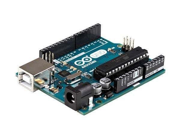
- Arduino UNO (or any other Arduino)
- LED MATRIX. We are going to use the FC-16 module which has four casacaded 8×8 LED Matrix Displays and a built-in MAX7219 LED Driver for each display.
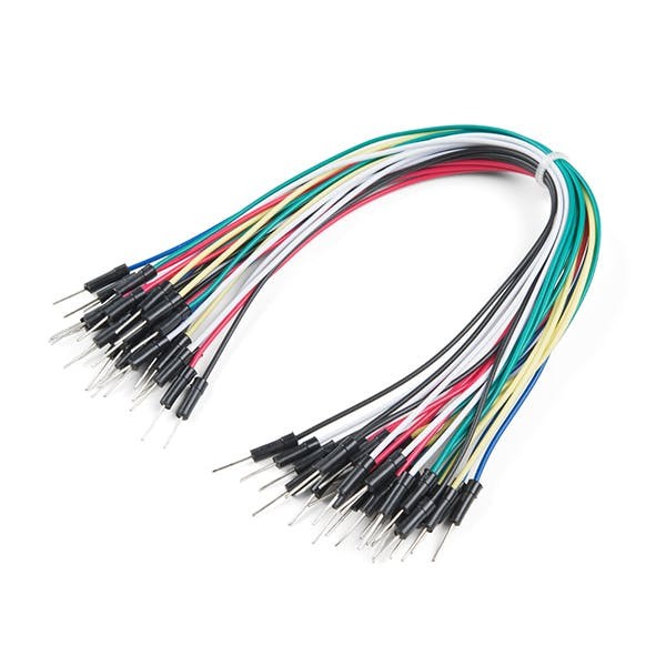
- Jumper wires
- Visuino program: Download Visuino
Step 2: The Circuit

- Connect LED Matrix pin[VCC] to Arduino pin[5V]
- Connect LED Matrix pin[GND] to Arduino pin[GND]
- Connect LED Matrix pin[DIN] to Arduino digital pin[11]
- Connect LED Matrix pin[CS] to Arduino digital pin[10]
- Connect LED Matrix pin[CLK] to Arduino digital pin[13]
Note: Read also the part for Troubleshooting below
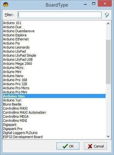
Step 3: Start Visuino, and Select the Arduino UNO Board Type
1 / 2
To start programming the Arduino, you will need to have the Arduino IDE installed from here: https://www.arduino.cc/.
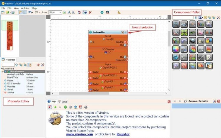
Please be aware that there are some critical bugs in Arduino IDE 1.6.6. Make sure that you install 1.6.7 or higher, otherwise this tutorial will not work! If you have not done follow the steps in this tutorial to setup the Arduino IDE to program Arduino UNO! The Visuino: https://www.visuino.eu also needs to be installed. Start Visuino as shown in the first picture Click on the "Tools" button on the Arduino component (Picture 1) in Visuino When the dialog appears, select "Arduino UNO" as shown on Picture 2
Step 4: In Visuino Add Components
1 / 5
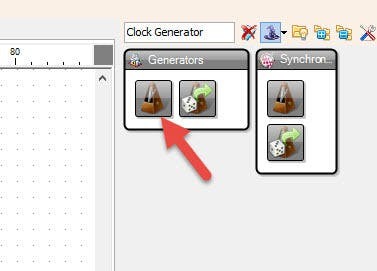
- Add "Clock Generator" component
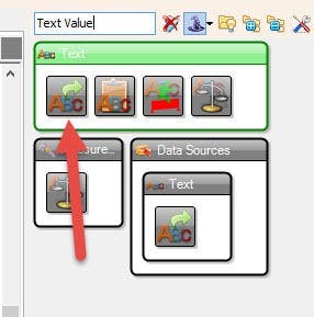
- Add "Text Value" component
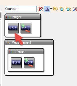
- Add "Counter" component
- Add "Integer Multi Source"
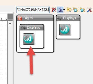
- Add "Maxim LED Display Controller SPI MAX7219/MAX7221" component
Step 5: In Visuino Set Components
1 / 11

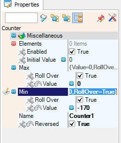
Select "Counter1" and in the properties window set Max>Value to 0 and Min>Value to -170Note: -170 is the distance on X (length of the text), that the text will travel from left to the right, you can play with this number to get the right lengthSelect "TextValue1" and set the "Value" (This is the text you want to display on the LED Matrix): ARDUINO LED MATRIX PROJECT
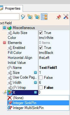
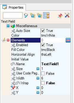
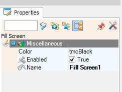
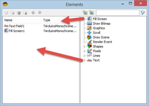
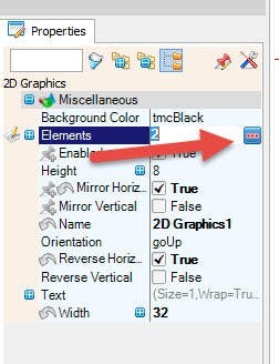
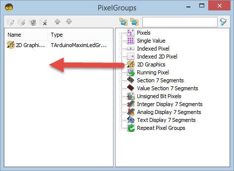
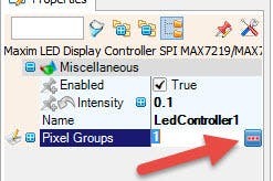
- Select "LedController1" and in the properties window select "Pixel Groups" and click on the 3 dots.In the "PixelGroups" window drag "2D Graphics" from right side to the left sideSelect "2D Graphics1" on the left side and in the properties window set :- "Height" to 8- "Mirror Horizontal" to true- "Orientation" to goUp- "Reverse Horizontal" to True- "Reverse Vertical" to False- "Width" to 32- Select "Elements" and click on the 3dotsIn the "Elements" window drag "Fill Screen" to the left, expand "Text" and drag "Text Field" to the left side.Select "Text Field1" and in the properties window set "Wrap" to False, Select "X" and click on the "Pin" icon and select "Integer SinkPin" <<see the pictureClose All windows
- Select "LedController1" and in the properties window set "Intensity" to 0.1 <
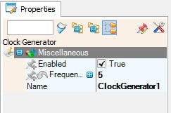
- Select "ClockGenerator1" and in the properties window set "Frequency" to: 5
- Select "IntegerMultiSource1" and in the properties window set "Output Pins" to: 3
Step 6: In Visuino Connect Components
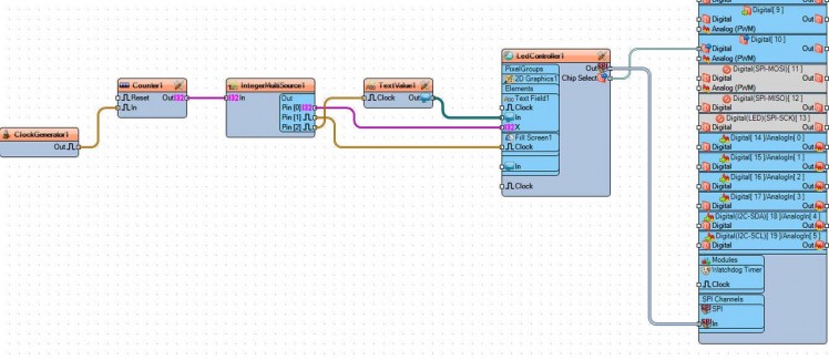
- Connect "ClockGenerator1" pin [Out] to "Counter1" pin[In]
- Connect "Counter1" pin [Out] to IntegerMultiSource1 pin [In]
- Connect "IntegerMultiSource1" pin[0] to "LedController1" > Text Field1 > X
- Connect "IntegerMultiSource1" pin[1] to "LedController1" > Fill Screen1 > Clock
- Connect "IntegerMultiSource1" pin[2] to "TextValue1" pin [Clock]
- Connect "TextValue1" pin[Out] to "LedController1" > Text Field1 > In
- Connect "LedController1" pin [Chip Select] to Arduino digital pin[10]
- Connect "LedController1" pin [Out SPI] to Arduino pin[SPI In]
Step 7: Generate, Compile, and Upload the Arduino Code
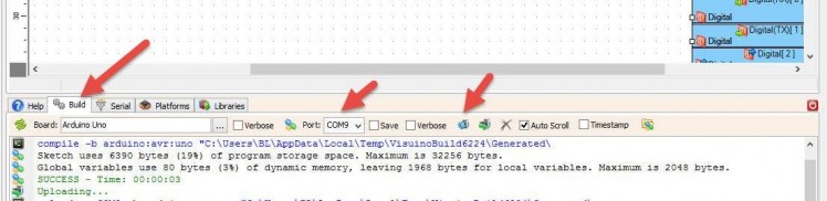
In Visuino, at the bottom click on the "Build" Tab, make sure the correct port is selected, then click on the "Compile/Build and Upload" button.
Step 8: Play
If you power the Arduino UNO module, the LED Matrix will start to Display the text from left side to the right side.
Congratulations! You have completed your project with Visuino. Also attached is the Visuino project, that I created for this tutorial, you can download it here and open it in Visuino: https://www.visuino.eu
Step 9: Troubleshooting
In my case When powering the Arduino the LED Matrix was blinking and the Text was not fully displayed. The reason for this was because MAX7219 chip is very sensitive to any voltage interference.
To solve that I added a 47uf electrolytic capacitor between the LED Matrix VCC(+) and GND(-), make sure you connect the capacitor right, + on (VCC) and - on the (GND)
Schematics, diagrams and documents
Code
Credits
Related products


Leave your feedback...