
Contactless Voltage Detector

Made by tarantula3 / Environmental Sensing / Home Automation / Notifications / Productivity / Sensors
About the project
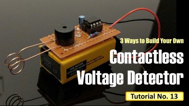
3 Ways to Build Your Own Contactless Voltage Detector For Less Than a Dollar
Project info
Difficulty: Easy
Estimated time: 1 hour
License: GNU General Public License, version 3 or later (GPL3+)
Items used in this project

Story
Contactless Voltage Detector
https://www.youtube.com/embed/Bw11igeWlEA
3 Ways to Build Your Own Contactless Voltage Detector For Less Than a Dollar
Introduction------------
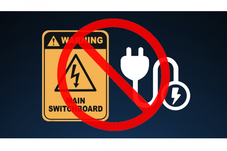
When electricity is not properly handled, it results in electrical shocks with a nasty experience; which is why safety must come first when working with electricity or electrical devices. In order to avoid injury, prior to starting work on an electrical box such as an AC mains switch-board or a power supply, you must first verify there is no AC voltage. It is really hard to completely isolate a device from the main supply; so, how can you be sure that there's no voltage remaining?
There are several options available in the market and they range in price, but if you don't want to spend a lot and if you are a true DIY lover, this Non-Contact AC voltage detector is the right choice for you. After watching this video you should be able to make your own AC tester for less than a Dollar.
Step 1: Topic Covered
 In this tutorial I am going to show you 3 ways of making your own Contact Less AC Voltage Detectors using:
- IC 4017 Decade Counter
- 555 Timer IC
- 3 x General Purpose NPN Transistors
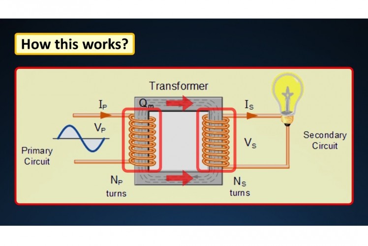 All these voltage detectors work on a simple principle of electromagnetic induction.A magnetic field is produced around a current carrying conductor and if current through the conductor is alternating current (AC), the magnetic field produced varies periodically. When we place an antenna near an AC energized object, a small current gets induced into the antenna due to electromagnetic induction. By amplifying this current we can light up a LED or a buzzer circuit, indicating that AC voltage is present.
Step 2: Setup Using IC 4017
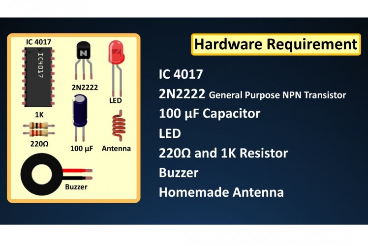 Lets start our discussion by assembling the circuit using IC 4017. IC 4017 is a 16 Pin Decade counter, it is used for low range counting applications. It can count from 0 to 10 (the decade count) sequentially in a pre-defined time and reset the count or hold it when required.For this setup we need:
- IC 4017
- 2N2222 General Purpose NPN Transistor
- 100 μF Capacitor
- LED
- 220Ω and 1K Resistor
- Buzzer
- and a Homemade Antenna
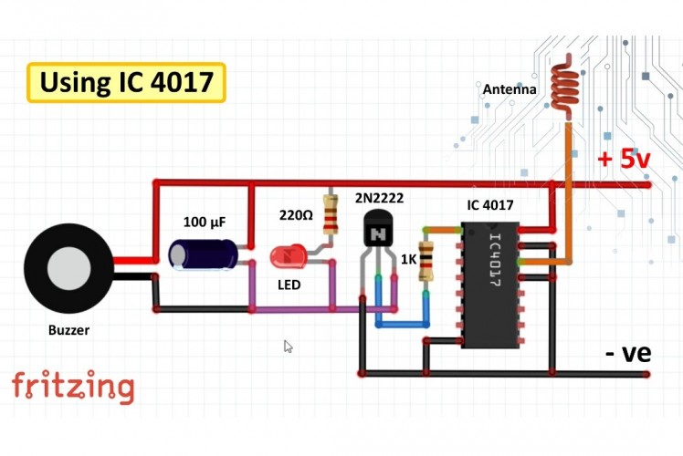
Connect Pin-1 of the IC to the 1K resistor. The other end of the resistor connects to the base of the transistor.Next connect the collector pin to the -ve legs of the LED, Transistor and the buzzer. The +ve legs connects to the +ve rail of the circuit-board. The negative rail connects to the Emitter, Pin-8, Pin-13 and the Pin-15 of the IC. The antenna is connected to the Pin 14 which is the clock input pin. When the antenna receives input clock pulses it advances the counter and the LED flashes. You can connect the cable connected to Pin-1 to any one of the Output pins of the IC. If you want you can also connect 3 or 4 LEDs to the Output Pins to give it a chaser like effect.4017
Demo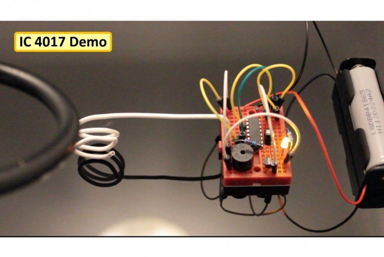 Now lets do a quick test. Moving a live wire close to the coil makes the buzzer and the LED to flash. But as you can see, at some instances the LED and the buzzer wont go off even after I move the wire away. Also, this setup flashes when I put my fingers around the coil. Pretty much every second video on YouTube is made using this hypersensitive IC. But frankly speaking I am not impressed by this setup.
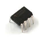
Step 3: Setup Using IC 555
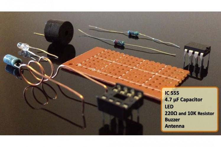
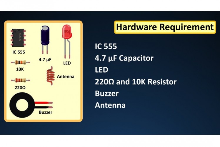 In the 2nd setup I am using the 555 timer IC.555 timer is the most common chip used in DIY electronics projects because it’s small, inexpensive, and very useful. This circuit is very simple. When the voltage on Pin-2 falls below 1⁄3 of VCC the Output on Pin-3 goes HIGH and the LED lights up. As long as this pin continues to be kept at a low voltage, the OUT pin will remain HIGH. So, when the antenna detects an alternating input the output goes HIGH and LOW and the LED flashes accordingly.For this setup we need:
- IC 555
- 4.7 μF Capacitor
- LED
- 220Ω and 10K Resistor
- Buzzer
- and a Homemade Antenna
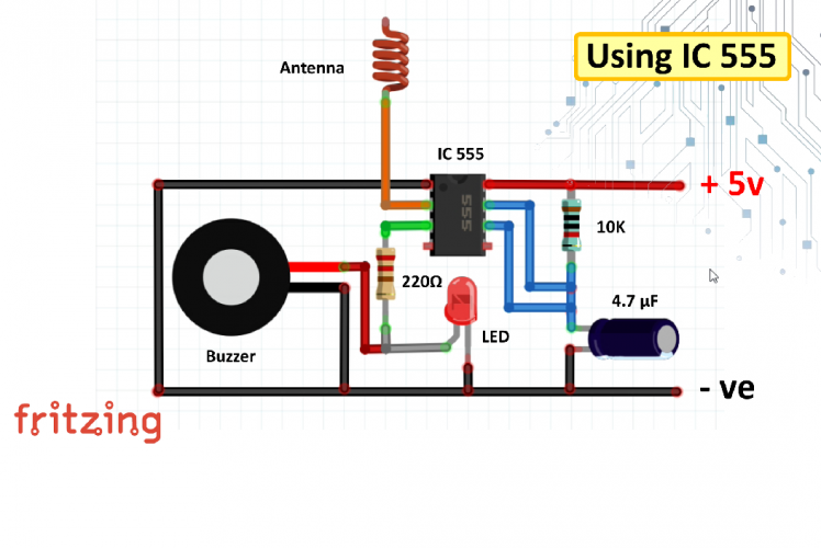 Connect Pin-1 to ground. Pin-2 to the antenna. Pin-3 to the LED and the buzzer. Pin-6 to the +ve leg of the capacitor and Pin-7 to one end of the 10K resistor. Then Pin-6 or the Threshold pin and Pin-7 or the Discharge pin need to be connected to each other. Pin-8 and the other end of the 10K resistor connects to the +ve rail of the circuit board, and finally connect all the -ve legs to the negative rail of the circuit board.555 Demo
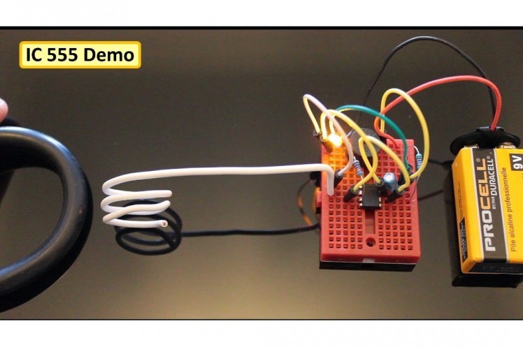 Alright, now lets do a quick test.As we bring a live wire close to the antenna the buzzer and the LED starts buzzing and flashing; and, if I put my hand around the antenna it has no effect on the circuit. Which makes this setup more reliable as I am not getting any false reading.
Step 4: Setup Using Transistors
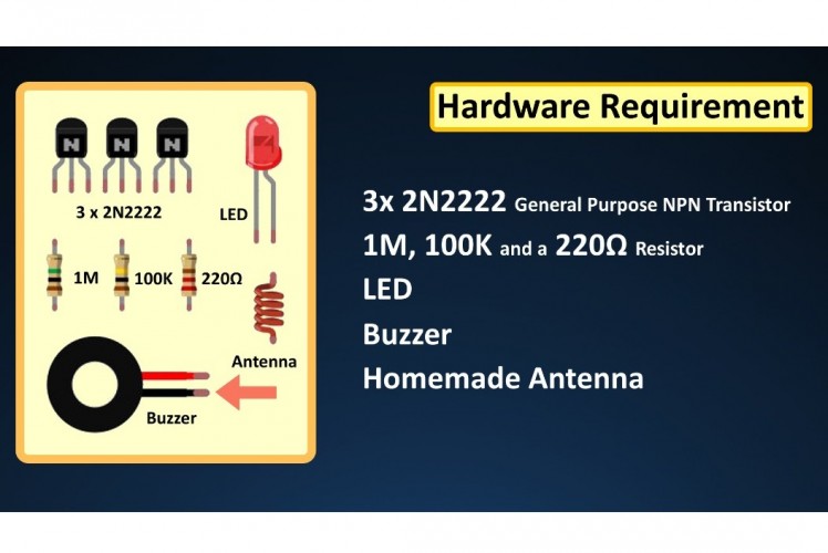 In the final setup I am using 3 2N2222 General Purpose NPN transistor.As we know a transistor has three terminals - emitter, base and collector. Collector to emitter current is controlled by the base current. When there is no base current, no current flows from the collector to the emitter. Thus, a transistor acts like a switch. So, a transistor can either ON, OFF or in-between.For this setup we need:
- 3 x 2N2222 General Purpose Transistors
- 1M, 100K and a 220Ω Resistor
- LED
- Buzzer
- and a Homemade Antenna
 Connect the antenna to the base of the 1st transistor. The emitter connects to the base of the 2nd transistor and same with the next one. Then connect the 1M resistor to the collector of the 1st transistor, 100K to the 2nd and the 220Ω in series with the LED and the buzzer. Then, connect all the resistors to the +ve rail of the circuit board. And finally ground the emitter of the 3rd transistor.Transistor Demo
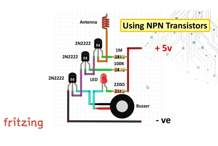 In this setup, the antenna is connected to the base of first transistor. When we move the antenna close to an AC energized object, a small current gets induced into the antenna due to the electromagnetic induction. This current triggers the first transistor and output of the first transistor triggers the second and third. The total gain (or the ratio of collector current to base current) would then be the multiplication of the three. The third transistor then turns ON the LED and buzzer circuit, indicating the presence of AC voltage.So, the brightness of the LED totally depends on the base-current. As the flow increases the LED's brightness goes high giving it a fading effect. You have to be really up close to get this thing to work. May be if I take the antenna's cover off it will perform well, but again this circuit was not able to impress me.
Step 5: Soldering
 I don't know about you but I really like the setup using the 555 timer IC. So, without wasting time lets start soldering all the components to the circuit board.
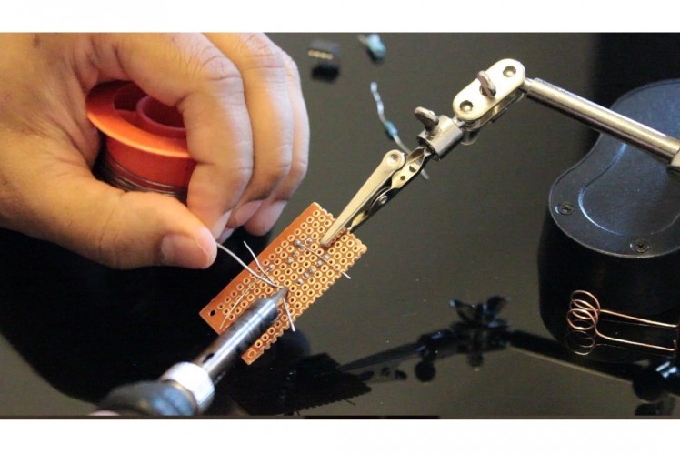 I'll start by soldering the base or the socket of the IC. An IC socket is used as a placeholder for ICs. They are used in order to allow safe removal and insertion of ICs because IC chips may get damaged from heat while soldering. Next, I am soldering the 220Ω Resistor, LED and the Buzzer to Pin-3 of the IC. After that, I am soldering the 10K resistor and the Capacitor to the board.
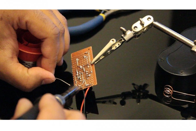 When considering household electric appliances, your safety is the main goal. If you are facing high bills, flickering lights and damaged appliances at your home, go ahead and make one of these to make sure that the home circuit is in proper working condition.Next, I am soldering the 9V Battery Snap-on Connector Clip to the plate. Once soldered, I am connecting all the +ve and -ve pins as per the circuit diagram. Once everything is in place its time for me to install the homemade antenna.
Testing
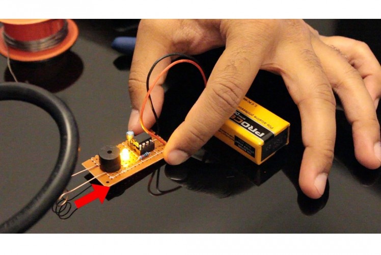
OK, now the interesting bit. Lets check out how this assembly works when a live wire is brought near to it. Looks like I have hit the jackpot. So, now you have no reason to blame the nation's power system when you have a poor wiring inside our home. Go ahead and check it NOW....
Credits
Related products


Leave your feedback...