
Connecting The Ds1302 Real Time Clock (rtc) With Visuino

About the project
Connect DS1302 Real Time Clock to Arduino Nano, and program it - quick and easy!
Project info
Difficulty: Easy
Estimated time: 1 hour
License: GNU General Public License, version 3 or later (GPL3+)
Items used in this project

Software apps and online services
Story
DS1302 Real Time Clock are widely available low cost RTC modules. They come with a clock and a small battery, and when connected to Arduino, can keep track of real time even when the Arduino board is not powered.
In this Tutorial, I will show you how easy it is to connect DS1302 RTC Module to Arduino, and read the time from it with Visuino.
Components
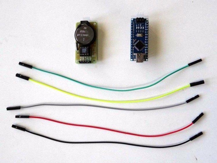
- One Arduino compatible board (I use Arduino Nano, because I have one, but any other will be just fine)
- One DS1302 Real Time Clock Module
- 5 Female-Female jumper wires
1 / 4 • Picture 1

Picture 1

Picture 2

Picture 3

Picture 4
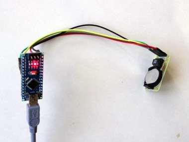
- Connect Power (Red wire), Ground (Black wire), CLK (Yellow wire), DAT (Green wire), and RST (Gray wire) to the DS1302 RTC Module (Picture 1)
- Connect the other end of the Ground wire (Black wire) to the Ground pin of the Arduino board (Picture 2)
- Connect the other end of the Power wire (Red wire) to the 5V power pin of the Arduino board (Picture 2)
- Connect the other end of the DAT (Green wire) to the Digital pin 2 of the Arduino board (Picture 3)
- Connect the other end of the CLK (Yellow wire) to the Digital pin 3 of the Arduino board (Picture 3)
- Connect the other end of the RST (Gray wire) to the Digital pin 4 of the Arduino board (Picture 3)
- Picture 4 shows the Arduino Nano pins that ware connected in this step
1 / 2 • Picture 1

Picture 1

Picture 2
Please be aware that there are some critical bugs in Arduino IDE 1.6.6. Make sure that you install 1.6.7 or higher, otherwise this Tutorial will not work!
- Start Visuino as shown in the first picture
- Click on the "Tools" button on the Arduino component (Picture 1) in Visuino
- When the dialog appears, select "Arduino Nano" as shown in Picture 2
1 / 3 • Picture 1

Picture 1

Picture 2

Picture 3
- Type "rtc" in the Filter box of the Component Toolbox then select the "Real Time Clock(RTC) DS1302" component (Picture 1), and drop it in the design area
- Click in the "Control" box containing the "Data", "Clock", and "Enable" pins of the RealTimeClock1 component to start connecting all the pins at once (Picture 2)
- Move the mouse over the "Digital" input pin of the "Digital[ 2 ]" channel of the Arduino component. The Visuino will automatically spread the wires so they will connect correctly to the rest of the pins (Picture 2)
- Connect the "Out" output pin of the RealTimeClock1 component to the "In" input pin of the "Serial[ 0 ]" channel of the Arduino component (Picture 3)
1 / 2 • Picture 1

Picture 1

Picture 2
- In Visuino, Press F9 or click on the button shown on Picture 1 to generate the Arduino code, and open the Arduino IDE
- In the Arduino IDE, click on the Upload button, to compile and upload the code (Picture 2)
1 / 3 • Picture 1

Picture 1

Picture 2

Picture 3
Congratulations! You have completed the project.
Picture 1 shows the connected and powered up project.
If you open Serial Terminal in the Arduino IDE or Visuino, you will see the date and time from the Clock (Picture 2)
On Picture 3 you can see the complete Visuino diagram. Also attached is the Visuino project, that I created for this Tutorial. You can download and open it in Visuino: https://www.visuino.com
Credits
Related products


Leave your feedback...