
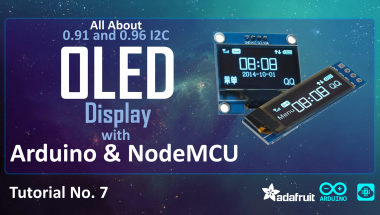
Complete Tutorial On I2c Oled Display Using Arduino/nodemcu

Made by tarantula3 / Displays / Home Automation / Productivity / Sensors / Wearables
About the project
In this tutorial I will be showing you how to get started with the small 0.91 and 0.96 I2C OLED displays with Arduino and NodeMCU.
Project info
Difficulty: Easy
Platforms: Arduino, Everything ESP, NeoPixel, NodeMCU
Estimated time: 1 hour
License: GNU General Public License, version 3 or later (GPL3+)
Items used in this project
Hardware components


View all
Story
OLED I2C DISPLAY ARDUINO/NODEMCU TUTORIAL
The very first program you write when you start learning anew programming language is: "Hello World!".
The program itself does nothing more than printing a “Hello World” text on the screen.
So, how do we get our Arduino to display the "Hello World!"?
In this video, I will be showing you how to get started with the small 0.91 (128x32) and 0.96 (128x64) I2C OLED displays.
There are 100s of tutorials on the web explaining the same thing in different ways, but I couldn't find one that tells me all about the OLED display and how to use it in different scenarios. It took me some time to work it all out. So, I thought I should create a tutorial on what I have learned and combine all the features and ways the OLED displays can be used in our projects.
Step 1: Things We Are Going to Learn Today
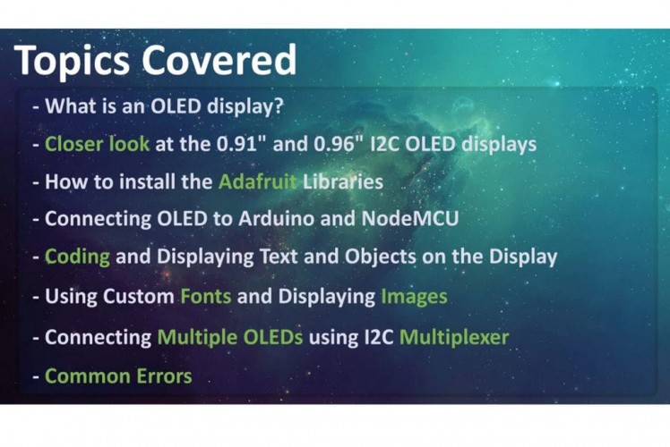
In this video we will be talking about:
- What is an OLED display?
- Then we will have a closer look at the 0.91 (128x32) and 0.96 (128x64) I2C OLED displays
- Next we will talk about installing the Adafruit Library to your Arduino IDE
- Then we will connect NodeMCU and Arduino to an OLED display
- Next we will have a look at the code and display some graphics and text on it
- We will also talk about applying Custom Fonts and displaying Images
- Then we will connect Multiple OLEDs to a micro-controller using I2C Multiplexer
- Finally, we will talk about few common errors people make while using the OLED displays
Step 2: Hardware Requirement
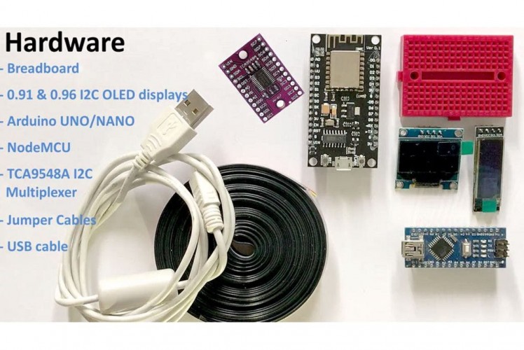
For this tutorial we need:
- A Breadboard
- A 0.91" (128x32) and 0.96" (128x64) I2C OLED displays
- Arduino UNO/NANO (whatever is handy)
- NodeMCU
- TCA9548A I2C multiplexer
- Few Connecting Cables
- and a USB cable to upload the code
Step 3: What Is an OLED Display?
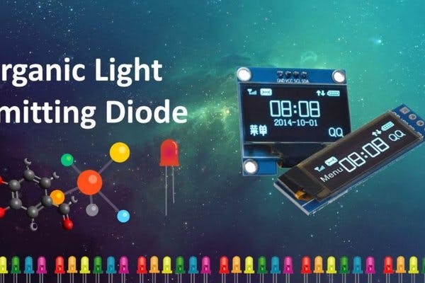
OLED or organic light-emitting diode is a light-emittingdiode (LED) in which the emissive electroluminescent layer is a film of organic compound (millions of small LED lights) that emits light in response to an electric current.
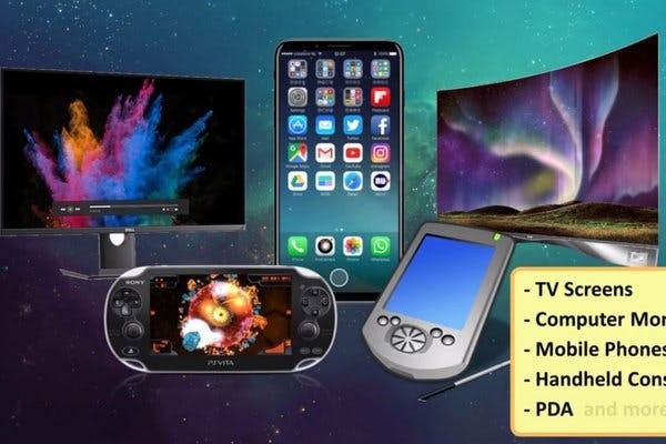
OLEDs are used to create digital displays in devices such as television screens, computer monitors, portable systems such as mobile phones, hand-held game consoles and PDAs. An OLED display works without a backlight because it emits visible light.
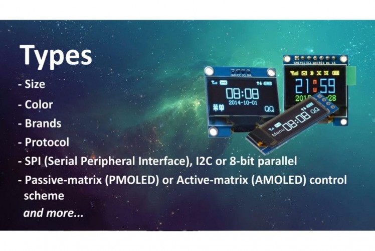
There are many types of OLED displays available in themarket based on their
- Sizes
- Color
- Brands
- Protocol
- SPI (Serial Peripheral Interface) or I2C
- Passive-matrix (PMOLED) or active-matrix (AMOLED) control scheme
In this tutorial, I am going to talk about connecting theblue color 0.91 (128x32 OLED) and 0.96 (128x64 OLED) I2C OLDE displays to an Arduino NANO and NodeMCU. I2C bus technology uses only 2 pins of the MCU so we have heaps available for other sensors.
Step 4: Closer Look
Lets have a closer at these two displays.
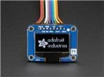
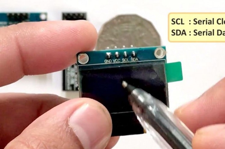
At the back of these displays there are heaps of SMD capacitors and resistors soldered on-board; but, since its an I2C device we only care about these 2 pins (SCL and SDA)
The display connects to Arduino using only four wires – two for power (VCC and GND) and two for data (serial clock SCL andserial data SDA), making the wiring very simple. The data connection is I2C (I²C, IIC or Inter-Integrated Circuit) and this interface is also called TWI (Two Wire Interface).
- The on-board pins can be in different order, so always triple check before hooking it up to your project.
- Operation voltage is between 3v to 5v but, it is best to use the guidance from the manufacturer's datasheet.
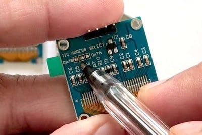
- Sometimes we need to use 2 displays in our projects. So, how can we achieve this?
The trick is to have a configurable address on your display. This unit has a configurable address between 0x78 and 0x7A. Just by unsoldering the 0Ohm resistor from one side and hoking it up to the other side or just by putting a global solder we can change the address. We will talk about it in depth when we hook up multiple displays to an Arduino in the later section of this tutorial.
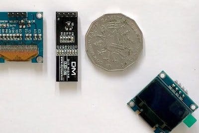
In picture these displays look very big. But, practically speaking they are tiny. They are made of 128 x 32/64 individual OLED pixels and do not require any back-light. Just have a look at this and see how small it is. Even though they are small they can be very useful in any electronic projects.
Step 5: Library

There are several libraries available to control thesedisplays. In past I have used the "u8glib library" but I find the AdaFruit library very easy to understand and use in our projects. So, I am going to use the AdaFruit library in this tutorial.
To control the OLED display you’ll need the "adafruit_GFX.h" library and the "adafruit_SSD1306.h" library.There are two ways you can download and install the library to your Arduino IDE.
Method 1
Go to the "Library manager" and search "adafruit_SSD1306" and "adafruit_gfx"Select the latest version and hit the Install button.Once installed you can use these libraries in your program.
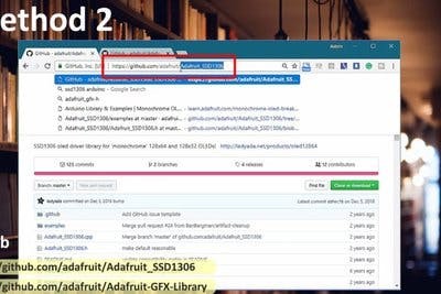
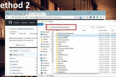
Method 2
These two libraries can be also be downloaded from github (you need both):I will provide the links in the description below.The display library: https://github.com/adafruit/Adafruit_SSD1306The GFX library: https://github.com/adafruit/Adafruit-GFX-LibraryOnce downloaded, copy the Adafruit_SSD1306-master folder from the downloaded zipped file into the Arduino libraries folder. This folder is usually found at Documents > Arduino > libraries on Windows systems. On Linux it is usually found at home folder > Arduino > libraries. Finally in the Arduino library folder, rename the Adafruit_SSD1306-master folder to Adafruit_SSD1306. Even if you don’t rename that’s fine.
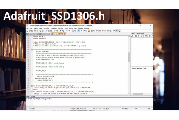
Now, lets have a look at the "Adafruit_SSD1306.h" file
Two things we need to know in this library:
1. If you want to use the smaller display use the default 128_32 otherwise for the bigger display comment the 128_32 and uncomment the 128_64
2. If you have soldered the 0x7A Address on the board (which we will talk about later) then use the 7 bit 0x3D address for the bigger displays, otherwise use the default 0x3C address. For the smaller displays the address is 0x3C.
Step 6: Wiring 128 X 64/32 OLEDs
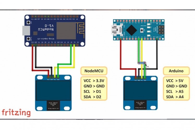
Lets start by connecting the NodeMCU to the display.
The first and most important thing to note is that some ofthe displays may have the GND and VCC power pins swapped around. Check yourdisplay to make sure that it is the same as the image. If the pins are swapped, make sure to change the connections to the Arduino or NodeMCU.
- NodeMCU OLED Wiring
OLED VCC – NodeMCU 3.3V
OLED GND – NodeMCU GND
OLED SCL – NodeMCU D1
OLED SDA – NodeMCU D2
- Arduino Uno OLED Wiring
OLED VCC – Arduino 5V
OLED GND – Arduino GND
OLED SCL – Arduino Uno A5
OLED SDA – Arduino Uno A4
- Arduino MEGA 2560 OLED Wiring
OLED VCC – Arduino 5V
OLED GND – Arduino GND
OLED SCL – Arduino MEGA 2560 pin 21
OLED SDA – Arduino MEGA 2560 pin 20
Step 7: Code
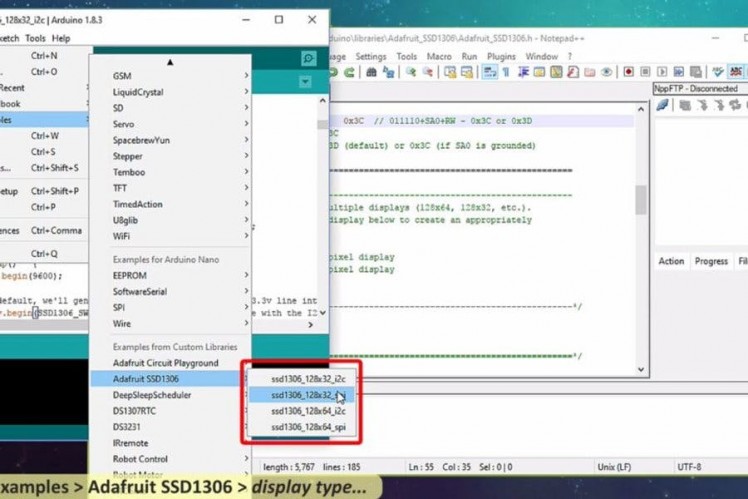
Adafruit library comes with really good examples for both128x32 and 128x64 displays.
The Library is located under File > Examples >Adafruit SSD1306 > and then the display type in the Arduino IDE.
We are going to use the 128x32 I2C example and will modifyit to work with both 128x64 and 128x32 displays fist by hooking it up to anArduino and then to a NodeMCU board.
The code starts by including both the Adafruit libraries. Inthis tutorial I am going to stress on only those parts of the code which arenecessary for us to load on both boards and displays. If you want to know moreabout the code please drop a comment on my blog or in the comments sectionbelow and I endeavour to get back to you.
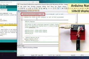
- First we are going to load the code to an Arduino Nanoconnected to a 128x32 display.
We can use the code as is without any modifications.
128x32 uses 0x3C address so this bit looks all good here, lets double check the header library, yes its also using the 0x3C address andthe display type is 128x32.
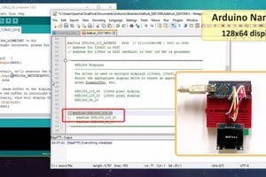
- Now lets connect the 128x64 display. As we know it usesthe 0x3C address by default so we don't need to update the address in eitherthe code or the library.
We just need we need to comment the 128_32 and uncomment the128_64 in the header library and change the LCDHEIGHT to 64 in our code.
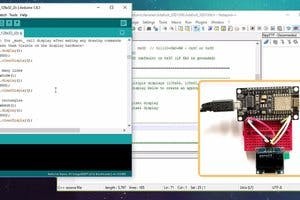
- Now to run the same code on a NodeMCU we need to changeone more line in our code.
The "#define OLED_RESET 4" > "#define OLED_RESET LED_BUILTIN" rest of the code is same as Arduino
Pretty much to display anything we first need to clear theprevious screen using
display.clearDisplay(); // Clear the buffer
Then draw the object
testdrawline(); // Draw a line
Show it on the hardware
display.display(); // Make them visible on the displayhardware!
Wait for some time before displaying the next item.
delay(2000); // Wait for 2 seconds
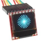
In this example we are displaying few items like text, lines, circles, scrolling text, triangles and more. Go ahead and use yourimagination and display whatever you want on these tiny displays.
Step 8: Customizing Text & Adding Images
Sometimes your code needs to display custom fonts andimages. If you are very good in bit mapping then you just need to create a bytearrays by turning on or off the tiny LEDs of the display to create custom fontsand images.
However, I am not very good in doing these mappings anddon't want to spend hours creating the bit map tables.
So, what are my options? I generally use two websites togenerate custom fonts and images. The links are provided in the descriptionbelow.
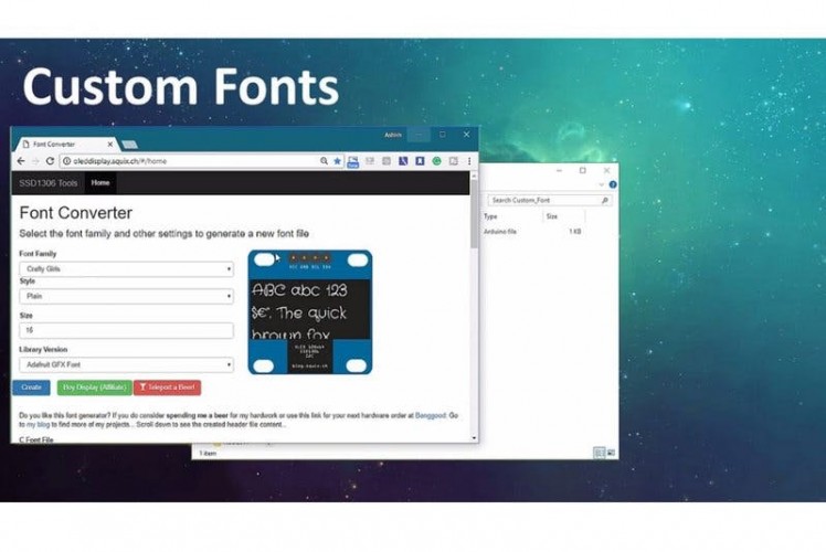
Custom Fonts
------------
Go to the font converter website, select the font family, style, size, Library Version as "Adafruit GFX Font" and then hit the"Create" button. On the right hand side of this page you can see howyour font is going to look like on the actual display.
Based on your selection the webpage generates the fontsheader file. Create a file called "modified_font.h" in the samefolder where your code is and copy and save the generated code into it. Thenyou just need to include the header file in your code to use the custom font.
#include "modified_font.h"
Then, you just need to set the font before displaying thetext to apply the custom font to it.
display.setFont(&Your_Fonts_Name);
You can get the name of the font from the header file youjust added to your project. Thats it, easy.
Memory is always a concern while using custom fonts, soalways consider the bytes that will be consumed by the memory. Just rememberArduino UNO has only 32K of memory.
If you want to create something different fromwhat is available on the website, check out the tutorial by Kris Kasprzak
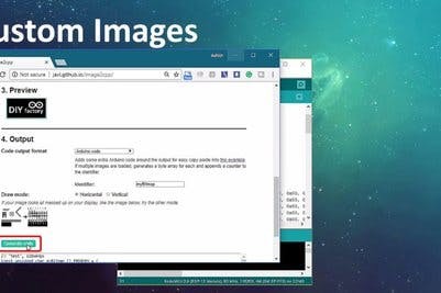
Custom Images
-------------
To display a bitmap image on your screen you first need tocreate a 128 x 64/32 sized image.
I am using the good old "MS Paint" to create a 128x 64 bitmap image which I will then upload to this image converter website. Thewebsite converts images into byte-strings, which can be used with Arduino andOLED displays.
Start by uploading the image to the website. Then put acheck on the "Invert image colors" check-box and change the"Output code format" to "Arduino Code" next select theorientation and hit the "Generate Code" button to generate the bytearray. The "Preview" section shows you how your image will look likeon the actual display.
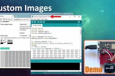
I have included the code along with this tutorial which youcan use to display your images. You just need to replace the array in my codewith the one you just generated and then load it to your Arduino.
Attachments
Step 9: Connecting 2 Displays
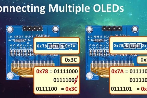
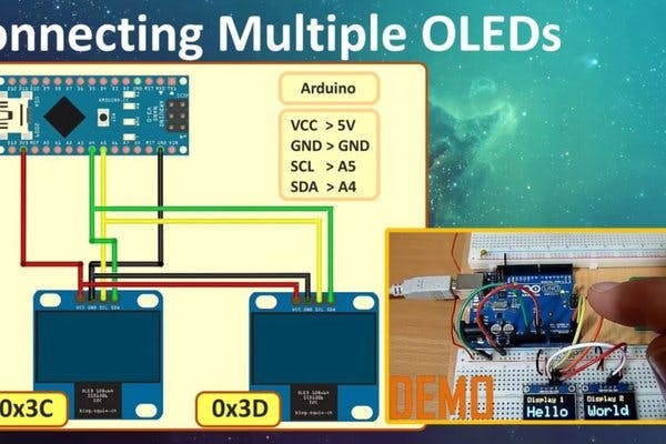
Connecting two 128 x 64 displays to your project is easy.You just need to unsolder the 0Ohm resistor from 0x78 address and put it on0x7A and then use the 0x3D address in your code instead of the default 0x3C.
You must be wondering why we are using the 0x3C and 0x3Daddress and not the actual 0x78 and 0x7A. Arduino accepts 7-bit address and notthe 8-bit hardware addresses. So, we first need to convert the 8-bit address tobinary, and then chop off the least significant bit to get the 7 bits. Thenconvert the 7 bits to HEX to get the 0x3C or 0x3D addresses which you enter inyour code.
First, initialize the display by giving it a unique name:
Adafruit_SSD1306 display1(OLED_REST);
Adafruit_SSD1306 display2(OLED_REST);
Then in your code use the display 1 and display 2 to callthe begin statements with the device addresses in them:
display1.begin(SSD1306_SWITCHCAPVCC, 0x3C); // display1 op address 0x3C
display2.begin(SSD1306_SWITCHCAPVCC, 0x3D); // display2 op address 0x3D
That's it, you can now go ahead and do whatever you wantusing either Display 1 or Display 2 in the rest of your code. I have providedan example with this tutorial.
Wiring is exactly the same as what we have done before, pretty much you just need to add another display to the same I2C pins of eitherthe Arduino or NodeMCU. Based on the addresses, the MCU then sends the data onthe I2C data line.
Attachments
Step 10: Connecting More Than 2 Displays
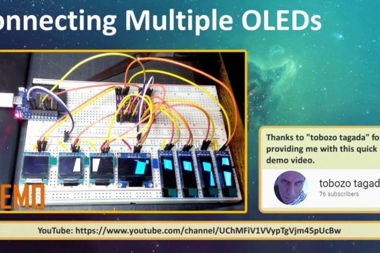

Now, what if you want to hook up more than 2 displays?
Arduino has limited number of pins and hence you cannot havemore than a certain amount of shields attached to it. Moreover, it hasonly one pair of I2C buses.
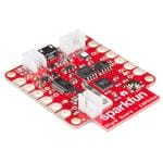
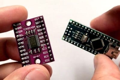
So, how can we attach more than 2 I2C displays to anArduino? The trick is to use a TCA9548 Multiplexer.
TCA9548 allows a single micro-controller to communicate withup to '64 sensors' all with the same or different I2C address by assigning aunique channel to each sensor slave sub-bus.
When we talk about sending data over 2 wires to multipledevices we then need a way to address them. Its same as the postman coming on asingle road and dropping the mail packets to different houses because they havedifferent addresses written on them.
The Multiplexer connects to 3V3, GND, SDA and SCL lines ofthe micro-controller. The slave sensors are connected to one of eight SCL/SDAslave ports on the board. The channels are selected by sending the TCA9548A itsI2C address (0x70 {default} - 0x77) followed by the channel number (0b00000001- 0b10000000). You could have at the max 8 of these multiplexers connectedtogether on 0x70-0x77 addresses in order to control 64 of the same I2Caddressed parts. By connecting the three address bits A0, A1 and A2 to VIN youcan get different combination of the addresses. I will explain this in-depth inmy next tutorial on TCA9548A breakout board. For now, lets just hook up 8 OLEDsto this board and have a quick look at the code.
Connection:
VIN to 5V (or 3.3V)
GND to ground
SCL to I2C clock
SDA to I2C data
Then wire up the sensors to VIN, GND and use one of the SCn/ SDn multiplexed buses
Now, Int the code lets start by including the"Wire" library and by defining the multiplexers address.
#include "Wire.h"
#include <U8glib.h>
#define MUX_Address 0x70 // TCA9548A Encoders address
Then we need to select the port we want to communicate toand send the data on it using this function:
void tcaselect(uint8_t i) {
if (i > 7) return;
Wire.beginTransmission(MUX_Address);
Wire.write(1 << i);
Wire.endTransmission();
}
Next we will initialize the display in the setup section bycalling "u8g.begin();" for each display attached to the MUX"tcaselect(i);"
Once initialized, we can then do whatever we want just by callingthe function "tcaselect(i);" where "i" is the value of themultiplexed bus and then sending the data and clock accordingly.
Attachments
Step 11: Advantages and Disadvantages
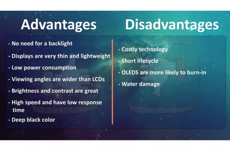
The image of an OLED is beautiful. However, OLEDs also havedisadvantages. Because OLED screens contain organic material, their lifespan is shorter than LCD displays. Additionally, many OLED displays get burn-ins after showing the same image for a long time. After a burn-in, the image stays on the screen even after showing another image. So make sure you keep refreshing the screen every few seconds. Water can instantly damage the organic materials of these displays.AdvantagesNo need for a backlightDisplays are very thin and lightweightLow power consumptionViewing angles are wider than LCDsBrightness and contrast are greatHigh speed and have low response timeDeep black colorDisadvantagesCostly technologyShort lifecycleOLEDS are more likely to burn-inWater damage
Step 12: Common Errors
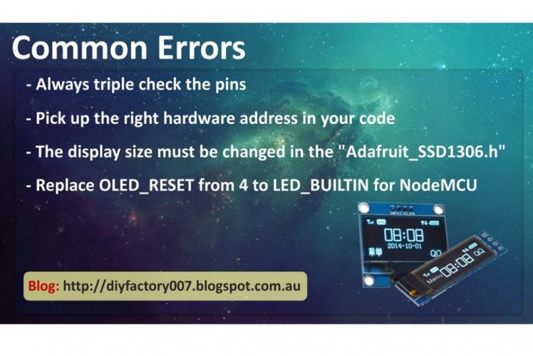
To conclude the tutorial lets talk about few common errorspeople make while using these displays:
- Always triple check the pins before using it in yourproject
- Pick up the right library address in the header file andin your code
#define SSD1306_I2C_ADDRESS 0x3C // inAdafruit_SSD1306.h
and
display.begin(SSD1306_SWITCHCAPVCC, 0x3C); // in yourcode
If the address is wrong the OLED will not displayanything
- The display size must be changed in the driver before itcan be used. If it is not changed you will get an error message when attemptingto verify the code
#error ("Height incorrect, please fixAdafruit_SSD1306.h!");
- If using NodeMCU make sure you replace the OLED_RESET from4 to LED_BUILTIN
#define OLED_RESET LED_BUILTIN
I have scene people making all sorts of things using thisOLED display. Some have even made video games and all. I am really notinterested in making a video game using this tiny display. However, I will nowleave you to explore your imaginations and come out with amazing ideas.
Attachments
Schematics, diagrams and documents
Credits
Related products


Leave your feedback...