
Cardboard Gun That Points At Your Face - Opencv And Arduino

Made by wheat-greaser / Artificial intelligence / Robotics
About the project
The next best thing after the invention of the wheel and the printing press. A robot that tracks your face and points a gun at it, it makes you feel like a racial minority. Here's the video where I show the process of making it:.
Project info
Difficulty: Moderate
Estimated time: 2 hours
License: GNU General Public License, version 3 or later (GPL3+)
Items used in this project
Hardware components


Software apps and online services
Hand tools and fabrication machines
Story
This is a tutorial on how to build the next big thing, Steve Jobs would be so jealous of you right now. A cardboard gun that points at your face. Why a cardboard gun? There is something inherently intimidating about cardboard, every time I look at a cardboard I am filled with fear and despair, I'm sure you feel the same way, but if you really don't , you can add lasers or another pointy thing at the end of the servo, the only real limit is your sanity.
To point a gun at a face you need to know where a face is, so we need to track the face we do it with OpenCv. The theory part behind the face tracking is explained in this video, so refer to that if you are interested in the theory. Okay firstly we need 2 libraries, one is opencv to track your face, and the other is pyserial to pass the coordinates of your face into the arduino. Do
- pip install opencv-python
and
- pip install pyserial
next go to your favorite text editor and create a new python file. Import these 3 libraries:
- import cv2
- import serial.tools.list_ports
- import time
we need the time library to create delays.
Next we need to define the port in which the arduino is connected.
- ports = serial.tools.list_ports.comports()
- serialInst = serial.Serial()
We also create a new serial instance. We get a list of all the ports connected to the device and add them to a list, then we get user input the user input will be the port in which arduino is connected, then we do a linear search on the list and set the port the user defined to be the port to which serial communications is to be established. Basically, get ports, add ports into a list, get user input for port in which arduino is connected, search for the port in the list of all ports. We do this migraine inducing procedure by
- portList = []
- for the_ports in ports:
- portList.append(str(the_ports))
- print(str(the_ports))
- which_port = input("COM")
- for i in range(0, len(portList)):
- if portList[i].startswith("COM" + str(which_port)):
- port_var = "COM" + str(which_port)
- print(portList[i])
Okay. Now we have to set the baudrate which is the rate at which the data is being transferred to the arduino.
- serialInst.baudrate = 9600
- serialInst.port = port_var
- serialInst.open()
In the above snippet we also set the port and open the serial.
Now we use opencv to open your default webcam and record your rather ugly face. We set the width and the height of the video to be 640 x 640.
- imcap = cv2.VideoCapture(0) # use shitty webcam camera
- imcap.set(3, 640) # width 640
- imcap.set(4, 640) # height 480
Now we use the pretrained model to track the face
- face_cascade = cv2.CascadeClassifier(cv2.data.haarcascades + "haarcascade_frontalface_default.xml")
For the explanation on how this works check out my video. I promise it is good. I also made a demo of this project there. So please. Check it out here.
The servo motor can move 180 degrees to the side and 180 degrees up and down but the image is 640 pixels wide and 640 pixels high, that means we need to scale the the coordinate values down to values that the servo can understand. So we scale it down by a scaling constant. Then we have to calculate the midpoint of the face, which we can easily do with the midpoint theorem. Then we pass the scaled down midpoint coordinates of the face into the arduino. To do this I used two functions.
- def write_read(x,y):
- serialInst.write(bytes(f'X{x} Y{y}', 'utf-8'))
- time.sleep(1)
- def servo_move(x,y,w,h):
- mynose_x = (x + w)/2
- mynose_y = (y + h)/2
- adjusted_mynose_x = mynose_x / (640/180)
- adjusted_mynose_y = mynose_y / (640/180)
- write_read(adjusted_mynose_x, adjusted_mynose_y)
- print(adjusted_mynose_x)
- print(adjusted_mynose_y)
- time.sleep(1)
Now we have to make an infinite loop to show the input video of the face with green rectangle drawn around your face, that's always a hit with the plebs. We do that with
- while True:
- success, img = imcap.read()
- imgGray = cv2.cvtColor(img, cv2.COLOR_BGR2GRAY) # convert image to grayscale
- faces = face_cascade.detectMultiScale(imgGray, 1.3, 5) # get corners around the face, set scale to 1.3 and set max number of neighbours to be detected to 5
- for(x,y,w,h) in faces:
- img = cv2.rectangle(img, (x,y), (x + w, y + h), (0, 255,0), 3) # draw a rectangle around face to make you look like a clown
- servo_move(x,y,w,h)
- cv2.imshow('face_detect', img) # show the now new image with the rectangles drawn in it
- if cv2.waitKey(10) & 0xFF == ord('l'): # exit when pressed L, because computer is salty
- break
if you press the L key in the keyboard the program stops running. And to close the video display window we do
- cap.release()
- cv2.destroyWindow('face_detect') # close window
Easy.
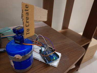
Now make the servo contraption. It is very simple.
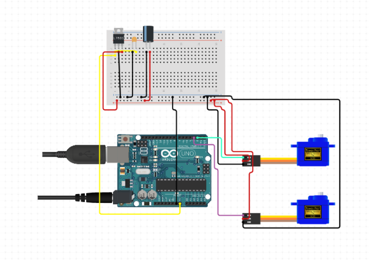
In the above image I connected the servo to the pins 2 and 3. That is incorrect, use pins 9 and 10 because 2 and 3 aren't pwm pins.
Just hotglue two servo motors together in such a way that one motor goes up and down and the other motor goes side to side. Now obtain a breadboard from a nearby bakery(get it, bread? haha I am a comedic genius). Connect the 5v pin of the arduino to the breadboard, then take two jumper male to male wires and take a connection from the breadboard into the two servo motors. Connect the orange wire of the x axis servo to pin 10 and the orange wire of the y axis servo to the pin 9, finally connect the ground wire of the servo to the ground pin of arduino. Contraption is ready. If you want to know how the servo contraption looks, take a look at this video and refer to it.
Now the arduino code is super simple.
Import the servo library and create a string variable to deal with the string received from serial data.
- #include <Servo.h>
- int x;
- int y;
- String serialData;
- Servo servo_x;
- Servo servo_y;
In the above snippet we also create the servo objects.
Now we have to setup the baudrate in which the serial data is received and the ports in which the servos are connected. I added the servo.write(0); to create a default state to calibrate servos. You should do it too.
- void setup() {
- Serial.begin(9600);
- servo_x.attach(10);
- servo_y.attach(9);
- Serial.setTimeout(15);
- servo_x.write(0);
- servo_y.write(0);
- }
Now we parse the string into an integer
- int parseDataX(String str){
- str.remove(str.indexOf("Y"));
- str.remove(str.indexOf("X"), 1);
- return str.toInt();
- }
- int parseDataY(String str){
- str.remove(0, str.indexOf("Y")+1);
- return str.toInt();
- }
We just play around with indexes so that we can convert the X80 Y90 string into numbers, we just need the 80 for the x axis and the 90 for the y axis.
Now we just pass the integer values into the servo
- void loop(){
- serialData = Serial.readString();
- x = parseDataX(serialData);
- y = parseDataY(serialData);
- servo_x.write(180 - x);
- servo_y.write(y + 70);
- delay(1000);
- }
In the above snippet I did the 180 -x for the x axis because the image is inverted in opencv so when I go right it shows that I go left and when I go left it shows that I go right, so if i do 180 -x it should show the correct place that I am in. I also did the Y + 70 to account for the webcam position because it is not in the same level as the servo, the webcam is raised, so I did that to account for that, you should play around with the code for a bit to tweak the settings.
So yeah. You just invented the next big thing, are you proud? I am not. Anyway, that's about it. See ya.
Code
Credits
Related products


Leave your feedback...