





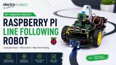
Build A Raspberry Pi Line Following Robot With Computer Visi

Made by chanchaldada / Artificial intelligence / Robotics / Sensors / IoT
About the project
Whether you're learning robotics or building an educational prototype, this project demonstrates how software and hardware work together to create an intelligent mobile robot.
Project info
Items used in this project
Hardware components



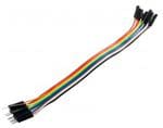
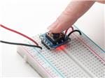
View all

Story
About the Project
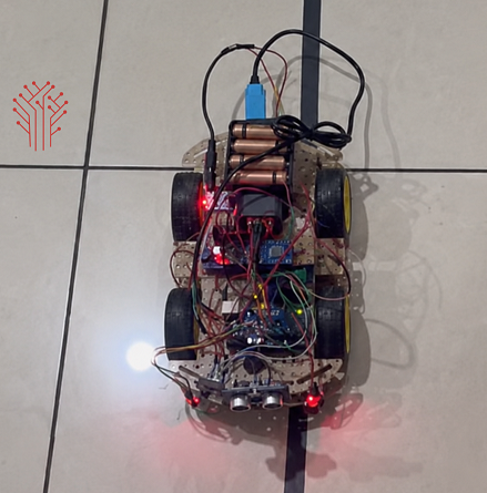
Line-following robots are among the best robotics projects for learning computer vision, motor control, and autonomous navigation. In this project, I built a Raspberry Pi-based Line Following Robot capable of detecting a track in real time and continuously adjusting its movement to stay on course. This robot is a great innovation of IoT.
Unlike simple IR sensor robots, this version uses Raspberry Pi processing power to analyze camera input, calculate the robot's position relative to the line, and control the motors with smoother and more accurate steering. The result is a flexible platform that can be expanded with obstacle detection, wireless monitoring, AI vision, or autonomous navigation features.
Projects like this are also an excellent way for aspiring raspberry pi developers to strengthen their understanding of embedded Linux, GPIO programming, computer vision, and autonomous robotics through practical implementation. This robot can detect the root; they can see the line and follow the line. This line following robot is very satisfying and easy to fix. In this line following robot raspberry pi can capture the images of what the user wants.
What You'll Learn
By completing this project you'll learn how to:
Capture live video using Raspberry Pi Camera
Detect a track using OpenCV image processing
Calculate line position in real time
Control DC motors through GPIO
Apply steering corrections for smooth movement
Build a scalable robotics platform for future AI projects
How the Robot Works
The Raspberry Pi continuously captures images from the camera mounted on the robot. Each frame is converted into a simplified representation where the target line can be isolated using thresholding techniques.
Once the line is detected, the software calculates its center position relative to the camera frame. If the line shifts left, the robot slows the left motor and speeds up the right motor. If the line shifts right, the opposite adjustment is made. When the line is centered, both motors rotate at equal speed, allowing the robot to move forward smoothly.
This continuous feedback loop enables the robot to follow complex paths with significantly greater accuracy than traditional sensor-only designs.
Step 1 — Assemble the Robot Chassis
Mount both DC motors securely onto the chassis.
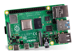
Install the caster wheel, battery holder, Raspberry Pi, motor driver, and camera module.
Ensure the camera faces slightly downward, so it captures the track clearly.
Step 2 — Wire the Electronics
Connect both motors to the L298N motor driver.
Wire the driver's control pins to the Raspberry Pi GPIO headers.
Connect the camera module using the CSI ribbon cable.
Finally, connect the battery pack and verify all power connections before switching on the robot.
Step 3 — Install the Software
Install Raspberry Pi OS and update the system.
Install Python dependencies including OpenCV, NumPy, and GPIO Zero.
Enable the Raspberry Pi Camera interface and verify that the camera captures images correctly.
Step 4 — Image Processing
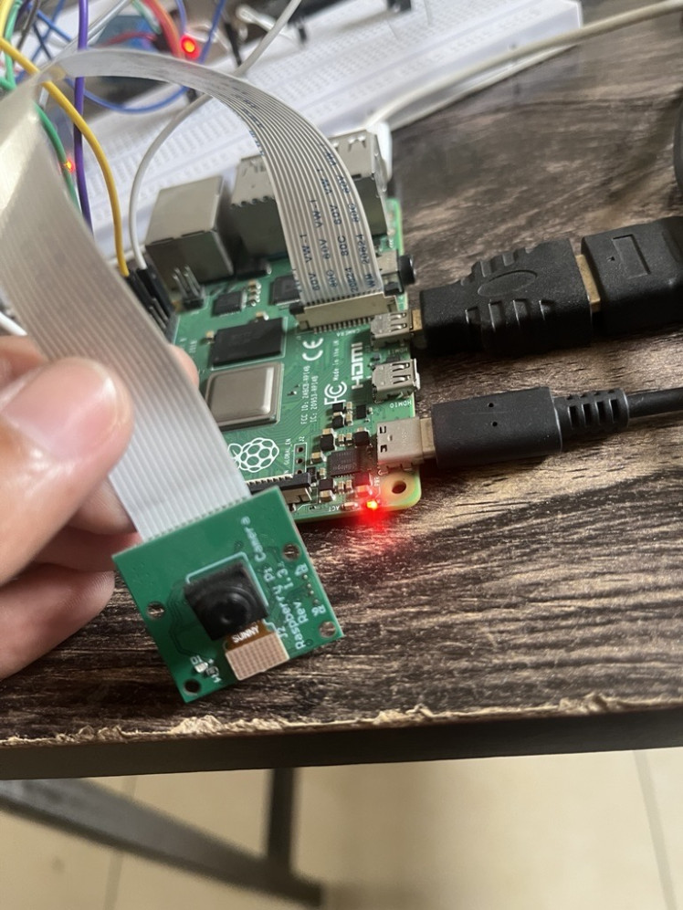
The camera continuously captures video frames.
The software performs:
Grayscale conversion
Image thresholding
Noise filtering
Contour detection
Center position calculation
These steps allow the robot to accurately identify the line even under varying lighting conditions.
Step 5 — Motor Control
After calculating the line position, the Raspberry Pi determines the steering correction.
Motor speeds are adjusted dynamically:
Line centered → Move forward
Line left → Turn left
Line right → Turn right
Line lost → Stop or search for the track
This feedback loop keeps the robot aligned with the path.
Testing the Robot
Begin testing on a simple black electrical tape track placed over a white surface.
Observe how the robot reacts to straight lines, curves, and sharp turns. Fine-tuning motor speed and steering parameters can significantly improve tracking performance.
Possible Improvements
This project can easily be expanded with additional capabilities:
PID Control for smoother steering
Obstacle avoidance using ultrasonic sensors
Wi-Fi remote monitoring
Live video streaming
AI-based object recognition
Autonomous navigation
Battery health monitoring
Final Thoughts
Building a Raspberry Pi Line Following Robot is an excellent way to combine embedded programming, computer vision, and robotics into a single hands-on project. Beyond simply following a line, this platform serves as a foundation for advanced autonomous robots that can navigate more complex environments with intelligent decision-making.
As your robotics skills grow, this project can evolve into a powerful experimental platform for machine learning, smart navigation, and real-world automation.
Although this robot is powered by Raspberry Pi, many robotics concepts—including motor control, sensor integration, and navigation logic—can also be adapted to Arduino-based platforms. Exploring different hardware architectures helps engineers better understand when teams choose to hire remote arduino developers for specialized embedded and automation projects.
Schematics, diagrams and documents
Credits
chanchaldada
Chanchal Dada is an IoT developer at DigitalMonk, focused on building smart embedded systems using Arduino and ESP32. She specializes in IoT-based automation, smart monitoring solutions, and real-world hardware-software integration for practical applications.
Related products





Leave your feedback...