
Buddybot: Controlling A Stepper Motor With An Android Smartphone

Made by mbparks / Animals / Home Automation / Lights
About the project
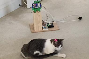
Chasing the infamous red dot of a laser pointer is a favorite hobby for our family's feline friend.
Project info
Difficulty: Difficult
Platforms: Arduino
Estimated time: 2 weeks
License: GNU General Public License, version 3 or later (GPL3+)
Items used in this project
Hardware components
![Ultrasonic module [Parallax] 28015 Ultrasonic module](https://www.mouser.co.uk/images/parallax/images/28015-l.jpg)

View all
Story
Summary
Sometimes you have an idea on how to solve a problem and look for the electronics to make it happen. Sometimes you have the electronics and must manufacture a problem to solve. This open source project is in the latter category and uses a stepper motor and the STM32 Nucleo to have a little fun with our four legged companions. Chasing the infamous red dot of a laser pointer is a favorite hobby for our family's feline friend.
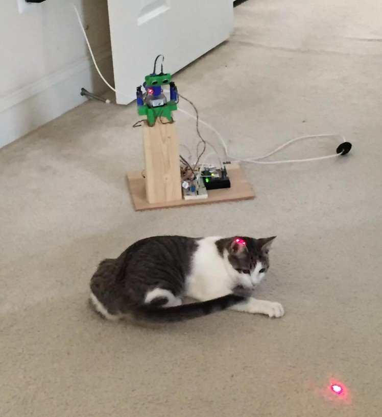
Figure 1: BuddyBot is an Android device-controlled laser pointer mounted on a stepper motor using a $10 STM32 Nucleo. Actual Bluetooth range is around 15 - 30 ft.
We're engineers and makers, so just waving around a laser pointer with our hand isn’t going to be enough; we must add a little electronic magic… This device will let the user control the laser pointer remotely via an Android app. We'll also add an automated "robot mode” to keep them entertained automatically. The schematic is provided in both .PDF and .SCH on the Source Files page.
Of course, this design can be easily hacked for other projects that have similar requirements to:
- Move a stepper motor remotely using an Android device as a remote control via Bluetooth.
- Move a stepper motor remotely at random.
- Use hardware interrupts.
- Practice basic circuit concepts such as the voltage divider and pull-up resistors.
- Use additive manufacturing techniques to build the "mechanical" portions of your electronics project.
Overview
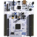
- The Brains: We will use an STM32 Nucleo F401RE microcontroller platform to tie all our components together. The STM32 Nucleo is programmed using the C/C++ language.
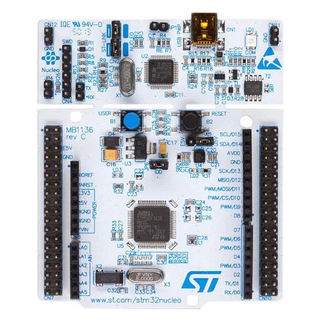
Figure 2: The STM32 Nucleo has a detachable, reusable programming card at the top that is removed once a project is ready for final deployment.
You will need a free account on mbed.org to use the STM32 Nucleo since their Integrated Development Environment (IDE) lives in the cloud. The benefits of having a cloud-based IDE are that:
- you are always running the latest IDE
- your code is backed up on their servers
- it makes adding third-party libraries a breeze.
We will use the latter feature to add a pre-built library to interface with our ultrasonic sensor so we can enable an automatic “robot” mode for our BuddyBot. I have also provided a link to the STM32 Nucleo code here to help get you started.
- The Brawn: A NEMA 17 stepper motor will provide the rotation of our laser and ultrasonic sensor. We will also use a L293D dual H-Bridge motor driver microchip to provide the interface and some protection between our microcontroller and the stepper. Important note: the ‘D’ at the end of L293D signifies that it has the built-in flyback protection diodes. There are also L293 chips that do not have the diodes, so be sure to pick the right ones when ordering if you don’t use the ones in the project cart already. The diodes are key in preventing blowback voltage from the motor coils from frying your microcontroller. Blowback voltage results when the power to the relay coil gets switched off and the magnetic field starts to fade. Current can flow back into your microcontroller if you leave it unprotected.
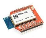
- Cutting the Wires: We will use a RN42 Bluetooth board to provide the serial communications link between our STM32 Nucleo and our Android app. To make things easy, we will be using MIT’s App Inventor software to develop our app. In addition, I have provided the .aia file if you want to upload it into your App Inventor account and tinker with the code. Or if you just want the app, Green Shoe Garage has published it in the Google Play Store.
The Build
- To begin, partition your breadboard into different parts. You will need space on the breadboard for the following components:
- L293D stepper motor interface chip and all the interface wires
- Terminal screw blocks for the laser
- 3 male header pins for interfacing to the ultrasonic sensor
- Voltage divider circuit to interface the STM32 Nucleo with the Bluetooth board
- Pull-down resistors for the motor limit switches
- Voltage regulator circuit
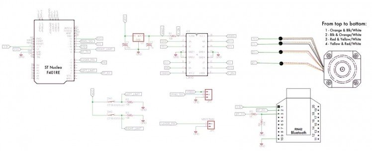
Figure 3: The BuddyBot Schematic. Click to enlarge.
2. Let’s start with the L293D H-Bridge Motor Driver Chip:
a. Gently secure the L293D chip into the breadboard to avoid damaging the pins.
b. Hook up the ground rail (GND) to the pins that need a connection to GND; this includes pins 4, 5, 12, and 13.
c. Run a 10k-ohm resistor for the Vcc rail to pin 1 which is the enable pin for the chip.
d. Run a wire from pin 1 to pin 9, which is also an enable pin.
e. Run Vcc directly into pins 8 and 16 to provide the power to drive the motors.
f. If we had a large load, we would have to use an external power source for these pins. But since the load is small, we can drive it off the 5V from the STM32 Nucleo with no problem. We will revisit this when we wire it up to the motor and the STM32 Nucleo later on.
3. Hooking up the laser:
a. If needed, extend the wires of the laser by soldering an additional length of wire. Be sure to insulate the solder point with electric tape or heat shrink.
b. Insert the screw terminal block onto the breadboard.
c. Connect one terminal of the screw terminal to GND.
d. Connect the GND wire of the laser to the GND terminal of the screw block.
e. Connect the Vcc wire of the laser to the other terminal of the screw block.
f. Connect a wire from the STM32 Nucleo pin PA_8 to the same row on the breadboard as the Vcc laser terminal.
g. This allows us to toggle the laser on and off in the software we will write later.
4. Hook up the PNG))) ultrasonic sensor:
a. Place a strip of 3 male header pins on the breadboard.
b. Then we provide a connection to Vcc and GND to the header pins.
c. The signal output pin of the ultrasonic sensor can be ran from the header pin directly into the STM32 Nucleo’s PA_6 GPIO pin. We will use the pulseIn function of the STM32 Nucleo to read in the ultrasonic sensor signal.
d. Ensure that you match the pins on breadboard to the pins on the PING sensor. Looking at the front of the PING sensor the order of the wires is SIG, Vcc, GND.
5. Limit Switches: To prevent the motor from turning a full 360-degrees and ripping out the laser and ultrasonic sensor wires, we will need to include two limit switches. Use the schematic to refer to, as well as instructions below. You also have an illustrated breadboard with which to follow along. Let’s wire the limit switches up next:
a. First let’s solder some pretty long wires to our micro lever switches.
b. Using a multimeter, check to see the normally open (N.O.) position for your switches. Solder a wire to each of the terminals. I prefer to use a red and green color wire to differentiate terminals.
c. We can’t let our STM32 Nucleo pins float when the switches aren’t depressed, so we will need 10k-ohm pull-down resistors for each switch. Repeat steps 1) through 3) below for both limit switches:
- Connect one end of the 10k-ohm resistor to GND and the other end into a row on the breadboard.
- Connect the red wire of the limit switch into the Vcc rail of the breadboard (the row marked +).
- Connect the green wire of the limit switch to the same row on the breadboard as the 10k-ohm resistor.
d. Connect the left limit switch to STM32 Nucleo pin PB_3 by tapping the point between our left limit switch and its 10k-ohm resistor.
e. The right limit switch will connect to pin STM32 Nucleo PC_7 by tapping the point between our right limit switch and its 10k-ohm resistor.
6. Voltage regulator: To ensure clean power on the breadboard we have a 7805 voltage regulator and some capacitors to filter out any noise. Wire the components as such:
- Place the 7805 into the breadboard.
- Connect the positive lead of the 10uF capacitor to Vin pin of the 7805.
- Connect the negative lead to the GND pin.
- Connect the positive lead of the .1uF capacitor to Vout pin of the 7805.
- Connect the negative lead to the GND pin.
- Connect the Vout pin of the 7805 to the Vcc rail of the breadboard.
- Connect the 5V pin of the STM32 Nucleo to the Vin pin of the 7805.
- Connect a wire from the GND pin of the 7805 to the GND rail of the breadboard.
7. STM32 Nucleo: Let’s next connect the STM32 Nucleo to the RN42 Bluetooth module. Most important in this step is to create a voltage divider circuit so that the STM32 Nucleo can safely talk to the RN42 Bluetooth module:
a. The STM32 Nucleo outputs 5V for logic high. However, the Bluetooth board can only tolerate up to 3.3V. A simple way to resolve this mismatch is to make a voltage divider circuit using a 5k-ohm and 10k-ohm resistor.
b. Ensure that one end of the 5k-ohm resistor connects to pin PA_9 on our STM32 Nucleo.
c. One end of the 10k-ohm resistor is connected to ground.
d. The remaining ends of each resistor will connect at a common node on the breadboard. We will tap off this node and run a wire to the Bluetooth TX pin, which is pin 3 on the RN42 breakout board.
e. The Bluetooth module RX pin (RN42, pin 2) can safely connect directly to the STM32 Nucleo on pin PA_10.
f. Connect the RN42 pin 1 to the STM32 Nucleo’s 3.3V pin.
g. Connect the RN42 GND pin to the breadboard’s GND rail.
When you are done your breadboard should look like this:

Figure 4: Illustrated BuddyBot Breadboard. Click to enlarge.
Now that the breadboard is wired for our components, we can go back in and add the wires that connect the STM32 Nucleo to the L293D and the L293D to the stepper motor. I chose to wire the motors last since there tends to be a lot of long wires involved and this prevents confusion when wiring up the earlier components.
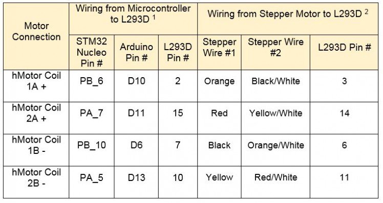
a. The particular stepper motors used here happen to split each phase into two separate coils (thus there are four coils in total). For this particular application, we will keep things simple by soldering together the 8 motor wires into 4 pairs of two wires. Specifically, we will solder together the following 8 wires coming from the stepper motor into these 4 pairs:
- Wire 1Y+ : Solid Orange wire with the Black/White wire
- Wire 1Y- : Solid Black wire with the Orange/White wire
- Wire 2Y+ : Solid Red wire with the Yellow/White wire
- Wire 2Y- : Solid Yellow wire with the Red/White wire
b. Next we will hook up these wires to our L293D in the following way:
- Wire 1Y+ connects to L293D pin 3
- Wire 1Y- connects to L293D pin 6
- Wire 2Y+ connects to L293D pin 14
- Wire 2Y- connects to L293D pin 11
c. Last, we need to connect the STM32 Nucleo to the L293D in the following way using some hook up wire:
- PB_6 to L293D pin 2
- PB_10 to L293D pin 7
- PA_7 to L293D pin 15
- PA_5 to L293D pin 10
This is what the wiring to L293D should look like (Figure 5b below):
That wraps up the hardware portion of the project. Go ahead and plug-in the USB cable to the STM32 Nucleo and see if the LEDs on the STM32 Nucleo and the RN42 Bluetooth module light up. If the little lights are blinking, then it’s time to move onto the software part of the project
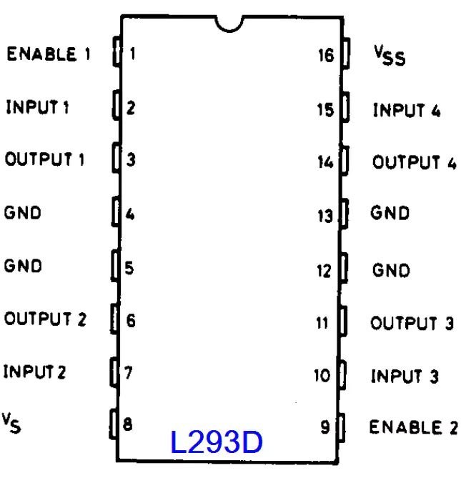
Figure 5a: L293D Pinout Click to enlarge.
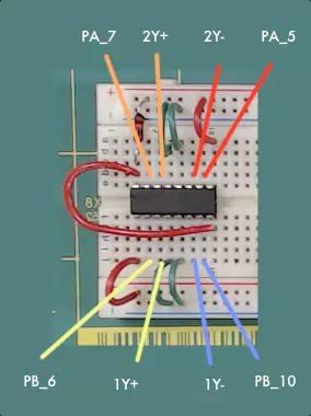
Figure 5b: Connect the motor and the STM32 Nucleo to the L293D. Click to enlarge.
Software
The BuddyBot project has two software components:
- Code that runs on the STM32 Nucleo and controls the motor, laser, and ultrasonic sensor.
- User Interface (UI) that runs on an Android device. They communicate with each other over a Bluetooth serial communications link that can be initiated from the Android app.
1. Let’s first take a look at the code that runs on the STM32 Nucleo. You can get the code from GitHub. In short, the code makes the STM32 Nucleo sit in a loop waiting for a character to be received from the Bluetooth module. Based on the character received, a variety of functions can be triggered. The first 25 lines of the main code looks something like this, and the filename on GitHub (at the time of this writing) is BuddyBot_v3_STM32 NUCLEO-f401RE.bin :
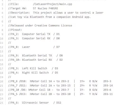
Figure 6: A section of the Nucleo main code from BuddyBot_v3_STM32 NUCLEO-f401RE.bin. You can look at an image file of the entire code in the Source Files area for this project as Nucleo_main_cpp.png, located inside BuddyBotNucleoCode.zip or get the code itself inside BuddyBotNucleoCode.zip or on github.
2. To drive the particular stepper motors we’re using, I wrote a custom library that contains motor.h and motor.cpp files, for download as images (.png files) in the Source Files area. (As image files, they are named: Nucleo_motor_h.png andNucleo_motor_cpp.png and are located in BuddyBotPhotos.zip with other images. The actual source code files motor.h, motor.cpp, and main.cpp are located in BuddyBotNucleoCode.zip)
Depending on how you construct your BuddyBot, there are a few key variables you may be interested in tweaking. In the main.cpp file:
- int triggerDistanceCM = 100: This variable is the minimum distance, measured in centimeters, between the ultrasonic sensor and your pet that will trigger a rotation of the motor when the BuddyBot is in robot mode. This will need to be adjusted depending on the height and angle of your ultrasonic sensor. The taller the sensor, the larger the variable may need to be.
In the motor.cpp file you may wish to tweak the following:
- int _numMotorPulseCycleStandard = 5: The number of motor rotation cycles that will run per click of the left or right button in the Android app. A smaller number will result in a smaller angle of rotation per each button press.
- int _numMotorPulseCycleMax = 10: This variable performs the same function as _numMotorPulseCycleStandard except it controls the number of rotation cycles that occur when an interrupt is triggered by the limit switches.
3. Once you have the code all written, click the “Compile” button to create the necessary .bin file that you will drop onto your STM32 Nucleo. You will be asked where you want to save the file to on your computer. Installing code on the STM32 Nucleo is as simple as dragging the file from wherever you saved it onto the STM32 Nucleo, just as you would click-and-drag any file onto a USB thumb drive.
Programming the Android App
4. Now let’s take look at the Android application (whose source code is located in the Source Files page inside AndroidApp.zip). The user interface (UI) of the Android application is minimalist and consists of the following elements:
- “Laser On” checkbox to toggle the laser on and off. If the checkbox is checked, the laser will turn on. If it is unchecked, the laser will turn off.
- “Robot Mode” checkbox to toggle the automatic mode. If checked, the motor will move at random without user input. The “Left” and “Right” buttons will be disabled while in auto mode.
- “Left” button will turn the motor to the left when in manual mode.
- “Right” button will turn the motor to the right when in manual mode.
- “Pair Device” button will allow the user to pair their Android device to the BuddyBot.
- “Connect” button will allow the user to connect to the BuddyBot after pairing the two devices.
- “Disconnect” button will only appear once a BuddyBot is connected. Pressing “Disconnect” will stop the connection between the Android device and the BuddyBot.
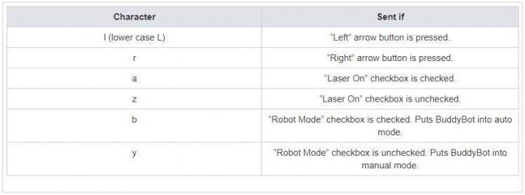
5. 5. The serial communications link is a simple, one-way link that passes single characters from the Android app to the BuddyBot hardware. The STM32 Nucleo code interprets each character and runs the appropriate function for each corresponding command character received. The following characters are sent based on the following button presses:
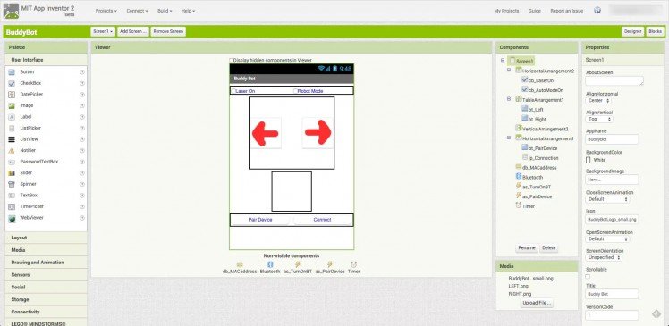
6. If you are so inclined to write the code yourself or modify the provided BuddyBot.aia file (inside AndroidApp.zip) , then the “Designer” window of your screen should look similar to this:
The “Blocks” window of your screen should look similar to this:
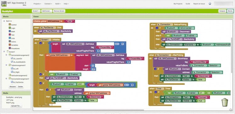
Figure 8a: Blocks window of the Android designer screen.
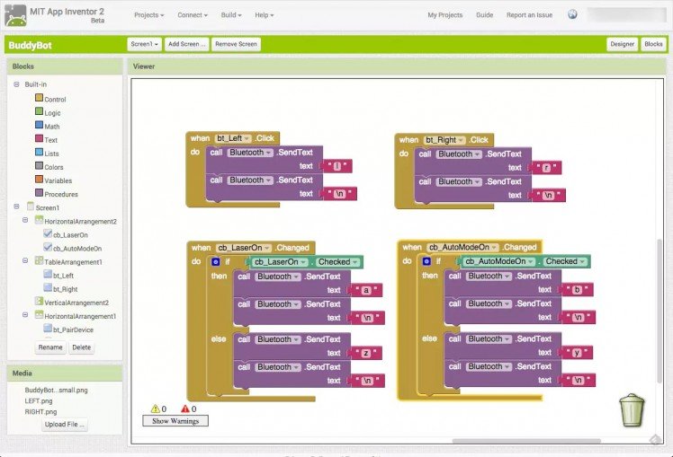
Figure 8b: Blocks window of the Android designer screen.
Assembly: Putting It All Together
As I mentioned in the Project Summary, I used a 3D printer to manufacture some of the mechanical interface components. I also used my amateur woodworking abilities to build the physical structure. Feel free to let your imagination run wild with laying out your BuddyBot. Some things to keep in mind though:
- Give it sufficient height, and angle the laser accordingly to give yourself ample room for the dot to traverse around your hardware. You don’t want Felix the Cat running into the box while chasing the laser.
- You may need to tweak certain variables in the STM32 Nucleo code such as triggerDistanceCM in the main.cpp file to account for the height and angle of your laser.
- Make sure to adjust the location of your limit switches so they are activated before the laser and PING sensor wires get wrapped up around the motor shaft.
- If you power the device from a USB wall charger (instead of a computer’s USB port), be sure to place a jumper across JP1, or else the STM32 Nucleo will not power the microcontroller.
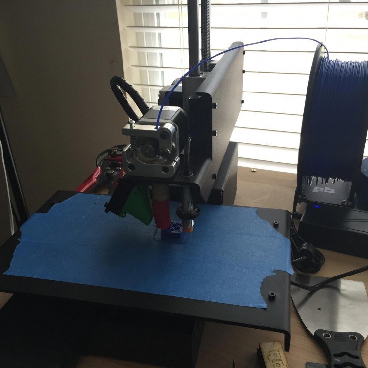
Figure 9: 3D printer files are provided for the enclosure if you have one, but is not necessary, depending on how violent your cat gets when it plays.
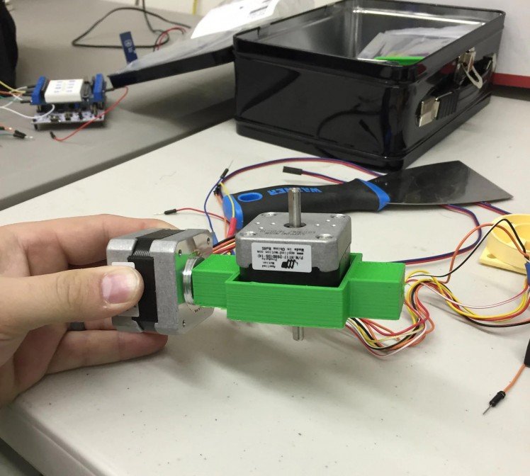
Figure 10: Assembly.
Time to fire it all up!
- Plug the USB cable into the STM32 Nucleo and into a wall outlet.
- Make sure that there are blinking LEDs on both the STM32 Nucleo and the Bluetooth module.
- Launch the BuddyBot app on your Android device.
- Click the “Pair” button to pair to the RN42 device. You should only have to ever do this once.
- Next click the “Connect” button and the blinking LED on the Bluetooth module should become solid.
- Try turning the laser on and moving the motor!

Figure 11: Testing the Buddy Bot in random mode. I also made a housing to put around it and protect the electronics from jumping cats.
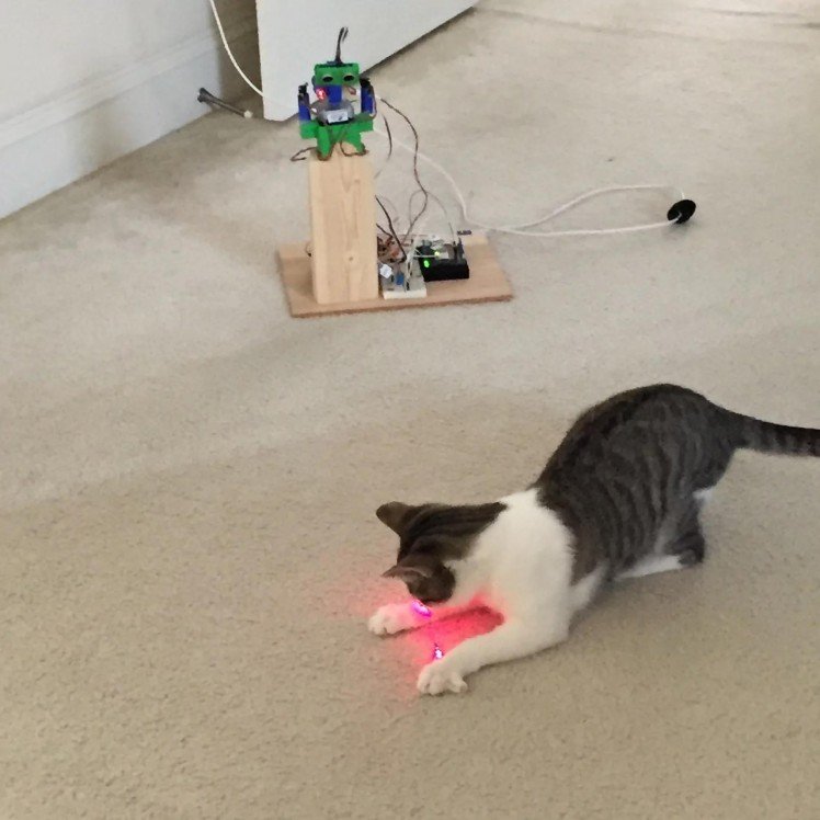
Figure 12: Testing the BuddyBot with my tablet. This is Bluetooth wireless, so you have to be within about 15 feet of BuddyBot to control it, but you could re-program the app to turn on in random mode at certain times of the day, if you’re willing to leave your tablet within 15 feet of Buddy Bot.
So there you have it, you’ve built your very own BuddyBot! Please send us pictures of your furry friend enjoying their new toy. If you make any modifications to the design, please share that as well. We can’t wait to see what you do!
Additional Resources:
STM32 Nucleo to Arduino Pin Layout Conversion “Cheat” Sheet
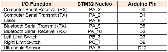
1. Nucleo header pins are identified by both a Morpho and Arduino pin identifier. STM32 Nucleo Pin # and Arduino Pin # refer to the same physical pin. The Arduino Pin # makes it easier to determine which pin to use since they are sequentially numbered.
2. Both Stepper Wire #1 and #2 must be connected to the associated L293D pin. (e.g. Both the solid orange and the black/white striped wires must connect to L293D pin 3)
RN42 Pin Layout “Cheat” Sheet

On the STM32 Nucleo
, Arduino™ connectivity support and ST Morpho headers make it easy to expand the functionality of the STM32 Nucleo open development platform with a wide choice of specialized shields. The STM32 Nucleo board does not require any separate probe as it integrates the ST-LINK/V2-1 debugger/programmer. The STM32 Nucleo board comes with the STM32 comprehensive software HAL library together with various packaged software examples, as well as direct access to mbed online resources.
The Microchip RN-42 Bluetooth Module is a small form factor, low power, class 2 Bluetooth radio for designer’s who want to add wireless capability to their products. The RN-42 supports multiple interface protocols, is simple to design in, and is fully certified, making it a complete embedded Bluetooth solution. The RN-42 is functionally compatible with the RN 41. With its high-performance, on-chip antenna and support for Bluetooth EDR, the RN-42 delivers up to a 3 Mbps data rate for distances up to 20 meters.
Source Files and Downloads
3D Printer Files: These STL files are used if you have a 3D printer to create the non-electronics portion of the project. 3D printing is not necessary to create the enclosure for project, however. Download them here as: 3DPrinterFiles.zip
Android Application files: Source files for the Android application that is used to control the BuddyBot from an Android device (tablet, smartphone, etc.) You need to be running the JellyBean release or higher on the device to ensure compatibility. Download here as: AndroidApp.zip
STM32 Nucleo Code: Original source files for programming the main STM32 Nucleo board. However, any subsequent revisions can be found on Github. Mbed.org is the tool used to program the STM32 Nucleo. Download here as: BuddyBotSTM32NucleoCode.zip
Images/Photos: Images of the BuddyBot and .PNG images of the original, commented source code are available here for download: BuddyBotPhotos.zip
Schematic Source files: This project wouldn’t be open source hardware without the source files for the schematics. There is no PCB (yet), or we would provide source for that, as well. SchematicSource.zip
Mbed.org houses free, cloud-based software dev tools available to program various ARM-based processors. Mbed.org
MIT App Inventor 2 is a free, cloud-based software development tool where you can learn the basics of programming apps for Android. MIT App Inventor 2
STM firmware updates can be found here: http://developer.mbed.org/platforms/ST-Nucleo-F401RE/
This project is licensed under CC BY-SA 4.0
Credits
mbparks
Mike Parks is the owner of Green Shoe Garage, a custom electronics design studio and security research lab located in Southern Maryland. He produces content for the Gears of Resistance which shares news and tips for those interested in the maker movement, open-source hardware and software, STEAM education, citizen science, and digital citizenship. He is also an extra class ham radio operator, a licensed Professional Engineer in the state of Maryland, and most notably a dad.
Related products


Leave your feedback...