
Bat Detector

Made by Al / Animals / Environmental Sensing / Sensors
About the project
Down-convert ultrasonics from MEMS microphone using heterodyne/Hilbert/CIC decimation ( no idea which yet!) down to audio frequencies say 0-5kHz. Not only pick up bats but listen to keys being dropped on glass tables and amuse your friends with 3-D printed dog-whistles!
Project info
Difficulty: Easy
Platforms: NXP
Estimated time: 1 hour
License: GNU General Public License, version 3 or later (GPL3+)
Items used in this project
Hardware components

Story
NXP Hackathon project using RT1010 dev board and should be fun!
There are many uses for this project: detecting bats, checking car ultrasonic intruder alarms, ultrasonic rodent repellers, ultrasonic tape measures, et cetera.
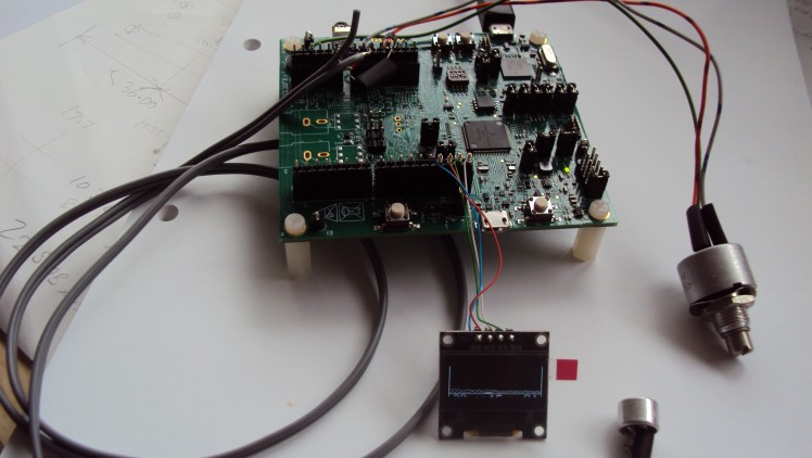
I really wanted something to down-convert ultrasonics so they could be heard by humans for a different project and it seemed like a good idea to do that for detecting bats. The RT1010 dev board's CPU has an on-chip 12-bit ADC capable of 1Msps, so would be ideal for connecting directly to an electret microphone. I have also added a pot to another audio channel so the tuning range can be adjusted from say 20kHz to maybe 100kHz. There is a Codec on the board with a tiny microphone but that would hardly exercise the CPU, which is the point of this exercise. The Crossover CPU can run at 500MHz so should be able to do a useful bit of signal processing in spite of a lack of DSP hardware.
Another strength of the RT1020 is the large amount of RAM, so one can use plenty of 1024-word buffers and not have to worry about running out of space!
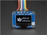
I added a tiny one-inch (approx) OLED display with I2C interface. This is quite neat as all four signals come out next to each other:
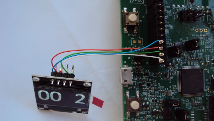
As you can see, I used wire-wrapping. Note two things: the SCL and SDA wires cross-over and of far more importance please remember that these Chinese displays sometimes have their GND and VCC pins swapped; it depends where you buy them from I guess. I discovered that once by trial and error. Luckily there was no Holy Smoke ;-) Follow the silk screen, Obi-wan!
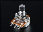
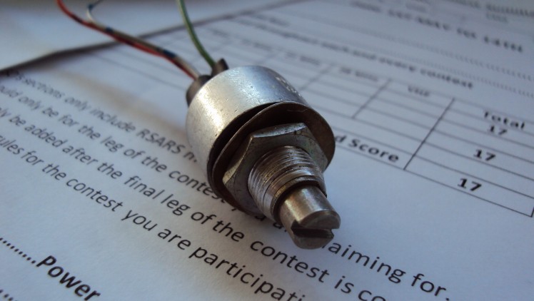
Here is a photo of the pot. It is a 10k linear, and happened to be sitting in the junk box. The display above is just displaying two zeros followed by the pot position converted to 0 to 6. Any value would do from 1k to 100k.
10k linear pot.
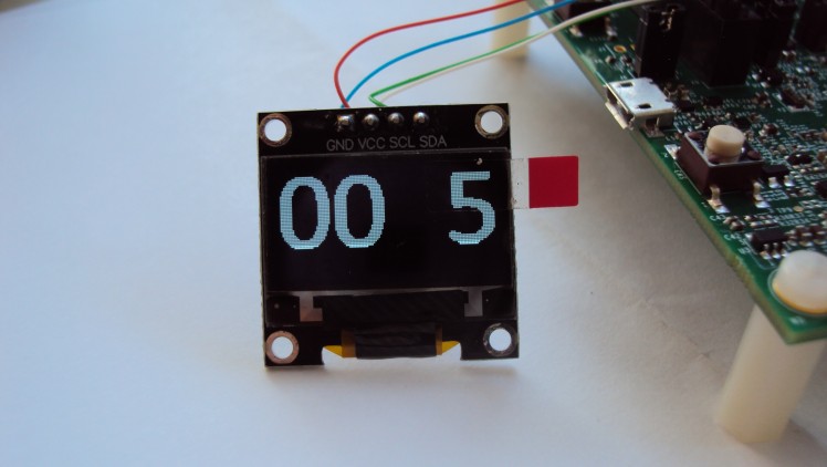
The display shows 00 5..., just to prove that I can talk I2C and initialise the OLED's controller. My software outputs four characters at the moment, where each character is a 32 wide by 64 pixel high bitmap. I made my own font up using graph paper. That work was done for my PIC-based capacitor meter, for which I generated the characters 0 to 9, a decimal point, and symbols for pF, nF and uF.
Here is a close-up of the display. I have left the tab on so I don't inadvertently scratch the surface.
Once the FFT is working, the display will look like a spectrograph, and display energy in 500Hz bands from 20kHz to (hopefully) 100kHz, or as high as I can get. Some bats go up to 120kHz.
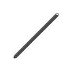
The last part is my ex-junk-box microphone.
I was originally intending to use a MEMS microphone, but they have several types of interface viz. audio, PDM and I2S, spec sheets for these tend to be cut off above 20kHz due to non-flat response sensitivity, and some digital interfaces deliberately limit the maximum frequency because they are mainly designed for mobile phones.
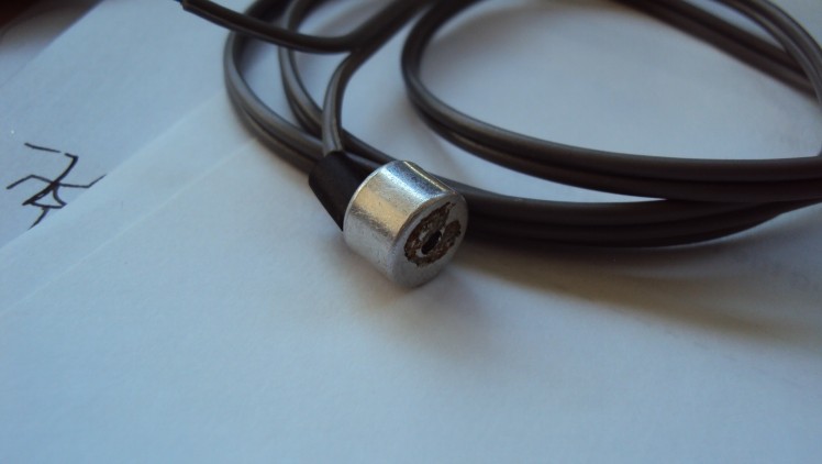
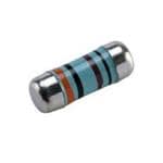
I have used twin audio coax cable and it is quite capacitive: 325pF per metre, according to my home-made capacitance meter ( see the RSGB's April 2021 RadCom article for more details ). Electret microphones require a pull-up resistor and that is fairly critical. I used 4k7. The idea is to ensure the microphone's DC output voltage is roughly half the supply voltage, which is 3.3V in this case.
Incidentally the ground pin is electrically connected to the case, and polarity is critical with these active microphones.
I was going to use the CPU's MQS (Medium Quality Sound) output, but could find no useful information as to how to set it up. Its 20dB SNR doesn't exactly sound like medium quality, so as you can see from the photos I have bottled out and used the Codec with its convenient 3.5mm stereo jack socket.
The biggest issue with programming the Crossover CPU is the lack of up-to-date relevant information. The free MCUXpresso IDE V11.3.1 is very good and compiles all the example code with no errors which is a great start. It also has a very useful ConfigTools setup feature with which you can connect up I/O pins to internal units such as GPIO, I2C etc. You can even connect the MQS Left and Right audio PWM subsystem to pins, but I have not discovered how you deal with the input side of the MQS. Anyway, that's a minor detail as I am cheating and using the Codec to generate audio output for this project. My only problem with Config Tools is that I seem to be unable to generate a new project from scratch that will allow ARM math to work, so I have built most of the supplied examples and cut/paste bits into one (SAI) that works with ARM Math.
Adding components works, e.g. the ADC, but you either need to cut/paste adc.c and adc.h or right-click on the red error message on the bottom right-hand corner of Config Tools. It is clever enough to add those files for you - very intelligent! The compiler is very fast. It takes about a second to compile small changes, and the code size is currently 167kbytes.
Debugging is easy. Some examples use PRINTF to display to the debugger window and others display at 115kBaud to a COM port so you need something like Putty running. The single USB lead does power, programming, debugging and displaying messages so is super-handy.
ARM's CMSIS DSP library contains the FFT routines for fixed and floating-point and both endians. Online chatter seems to suggest there are problems with using the Real FFT as opposed to Complex, but that could be due to people's incorrect use due to a lack of adequate information. I may discover when I get my teeth into it...it is ARM's responsibility rather than NXP's. There was some info on the Web that talked about getting the ARM library and changing the filename from .lib to .a and all sorts of other stuff - I did not have to do any of that.
The FFT should be straightforward: a sampling rate of 1Msps on two channels with 1024 points should give a bin resolution of about 500Hz. That can be displayed on the OLED. The height of each display bar can be proportional to received power or voltage. I plan to use peak detect with maybe a 5 second decay time. Bat squeaks can be very short so at least a long persistence display will be very useful.
Finally I intent to run a numerically-controlled oscillator between 20kHz and 100kHz, controlled by the pot. This frequency will be mixed with the received ultrasonic waves and down-convert like a superhet radio. If I was clever enough I could arrange sine and cosine oscillators and cancel out the unwanted sideband.
Well I was having loads of trouble getting the FFT to work: the FFT buffers have to be twice the size so that in-place operations do not overflow and also real data is converted to complex which takes twice the space.
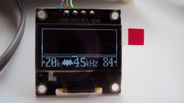
The display is working nicely and it displays the audio range 20kHz to 84kHz, ( so it is 64kHz wide and what with 128 pixels width display that makes it really easy to have each pixel as a 500Hz bin), a bat symbol and the frequency for audio down-conversion is shown. The latter is controlled by the pot in 5kHz steps.
The down-convert frequency is generated by PIT channel 0 in 4 steps like this:
step sine cosine
0 0 0
1 0 1
2 1 1
3 1 0
These outputs multiply the microphone ADC result by +1 or -1 to give my I/Q streams.
Latest photo with FFT working. The display starts at 20kHz on the left-hand side, and ends at 84kHz on the RHS. The down-converted audio bar is at 45Khz, and that bar sits just below the FFT output. Note that I have yet to get the audio out of the CODEC. The image is a bit dark as pixels seem to be multiplexed camera takes a snapshot. It looks fine in real life. If I get a chance I will try my old Canon 4M pixel camera because I can hold the shutter open for up to 15 seconds if I remember correctly.
The FFT display has a peak-detect persistence. I have set it to 2 seconds in Bat_Oled.c
// variable persistence...in millisecs
#define PERSISTENCE_MSEC 2000
but it could be set to hours or days if you like.
Here is a video showing the persistence....Persistence Video
Or on YouTube...
Memory size so far:
BOARD_FLASH: 167816 B 16 MB 1.00%
SRAM_DTC: 30628 B 32 KB 93.47%
SRAM_ITC: 0 GB 32 KB 0.00%
SRAM_OC: 0 GB 64 KB 0.00%
NCACHE_REGION: 0 GB 0 GB
Finished building target: evkmimxrt1010_sai_SAI_BatDet.axf
The project isn't quite finished: it all works but there is no audio output (yet).
1. The FFT display is linear and really needs to be logarithmic and more gain. My buffers are 16-bit integers for speed but it would be interesting to try floating-point instead.
2. The down-converted audio buffers i_data and q_data need to be lowpass filtered at between 5kHz and 10kHz and then added or subtracted for upper/lower sideband and then fed into the codec. They are in bat_fft.c if you wish to play!
How it works.
The mic is biased at approx half the supply voltage and fed into a 12-bit analogue input. Another analogue input comes from the pot. These are read at full speed so that should be about 500,000 samples per channel per second, nicely above the ultrasonic band. When 1024 samples have been read, the microphone buffer is copied over and the average voltage is found then subtracted thus giving a signed 16-bit value. If the ADC had an offset value per channel then that stage could be removed. There seems to be a global ADC offset but that would also affect the pot reading. The pot doesn't have to be read more than 10 times a second but it was easier to do it this way.
The signed mic data is fed into a real FFT. Note that FFT buffers have to be twice the size to allow for conversion to complex data. Each bin is 500Hz wide. As the display is 128 pixels wide it makes it easy to display the FFT result of a 64kHz band, so I chose 20kHz to 84kHz. Some bats go higher, the microphone is probably not that good anyway. The starting offset may easily be changed to 0Hz so the FFT display could be tested with audio to prove it works with a tuning fork/organ/violin/tone generator. I have not tried to do any accurate tests so there could be a few bugs in my code and the frequencies could be out.
A GPIO pin could be toggled by the ADC interrupt to determine the exact ADC sampling rate.
The OLED displays 4 'characters' of 64 pixels height and 32 pixels width. The 'characters' are in a lookup table in OLED3.h. FFT data is 'OR'-d over the 4 characters. The first character is '|<20kHz' to infer that the left side of the screen is at 20kHz. The next character is a bat symbol which could be flashed on the screen when an energy threshold is exceeded but I have hard-coded the bat . The right-hand half of the second character is the tens of kHz digit for the start of the audio down-conversion frequency - or heterodyne frequency. So there are 9 characters made up. The third character is the units of kHz and to be lazy, the heterodyne freq. jumps in 5kHz steps, so I only require a 0 and a 5. The final character is '84kHz->|'.
Each column stores the peak value and a persistence timer. When the timer exceeds a value such as 2 seconds, the peak value for that column is cleared. The value could be much longer, it is in milliseconds as a 32-bit long.
Meanwhile(!) the ADC mic sample is multiplied by +1 or -1 depending on a PIT count generating quadrature sin/cos, and fed into I and Q buffers. The plan is to low-pass filter these, add or subtract and feed the result to the Codec. But it may be possible to do some simple (i.e. quick) filtering in the interrupt service routine and send samples directly to the Codec. That is all for another day!
Criticism: the debugger uses 100% CPU time of one of my 4 cores ;-(
Schematics, diagrams and documents
Code
Credits
Al
Been a keen radio amateur for many years. HF CW activity when I get the chance...homebrew radios and gadgets from valve amplifiers using EL84s etc in the past to a TV sound-bar using an Arduino and Class-D amplifier. I have been trying to build an electronic organ for a while but technology changes before I get anywhere!
Related products


Leave your feedback...