
Autonomous Rc Ekranoplan With Computer Vision Following
About the project
Everything from RC airplane flight stabilization, lidar altitude hold integration to fly in ground effect, to the addition of a raspberry pi and computer vision algorithm to get the whole thing to follow behind me on an electric longboard.
Project info
Difficulty: Difficult
Platforms: Raspberry Pi, Teensy
Estimated time: 6 weeks
License: GNU General Public License, version 3 or later (GPL3+)
Items used in this project
Hardware components


View all
Story
Introduction
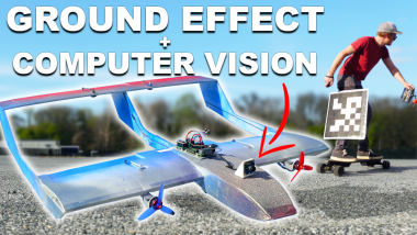
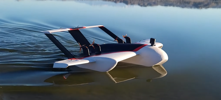
In a collaboration with the Think Flight Youtube channel, the deal was simple: Think Flight builds an awesome 7ft radio controlled ground effect vehicle, and I build the flight computer that will let it track and follow behind his boat with a computer vision tracking algorithm while he drives around. The only problem: How do you develop and test such a system while living on the East coast, while Think Flight lives on the West coast? It was the perfect opportunity to build my own ground effect vehicle, aka Ekranoplan, to test my yet-to-be-developed flight computer, tracking algorithm, and control scheme before sending the whole system out to be integrated on the 7ft aircraft:
Building My Test Platform
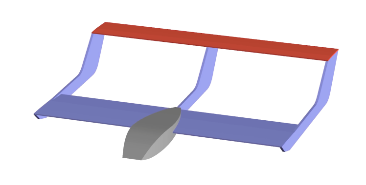
My Ekranoplan design to prototype on was a little simpler. I opted for foamboard and hot glue construction for a 40" wingspan airframe that could be beaten up during my testing. I sketched out the general design in Solidworks, printed out stencils for the parts, and threw together a pretty standard foamy RC airplane:
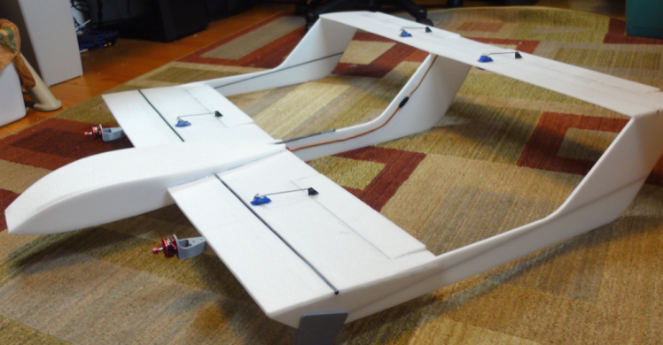
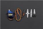
My Ekranoplan has two 1700kv brushless motors with 5" propellers, powered by a 1500mah 4s LiPo battery. Standard 9 gram servos actuate the ailerons, which can also be used as 'flaperons' (discussed later) and two elevons--which are used for both pitch and roll control. The horizontal stabilizer on my Ekranoplan is rather big compared to a regular RC plane, and for good reason. When flying close to the ground in...ground effect...the wing typically generates extra pitching moment. The T-tail design with the H-stab elevated out of ground effect ensures the pitch control authority is maintained. Making it larger further guarantees adequate pitch control through all flight regimes.
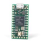
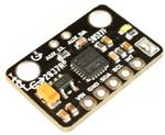
Technically, you don't need a flight controller to fly an RC plane, or even to fly in ground effect for that matter. But when handing controls off to an onboard computer to do the steering, it helps to have a well-stabilized aircraft that will self-level when no stick inputs are given. So, I integrated my own open-source flight controller, dRehmFlight VTOL, which runs on a Teensy 4.0 microcontroller and uses an MPU6050 IMU: https://github.com/nickrehm/dRehmFlight
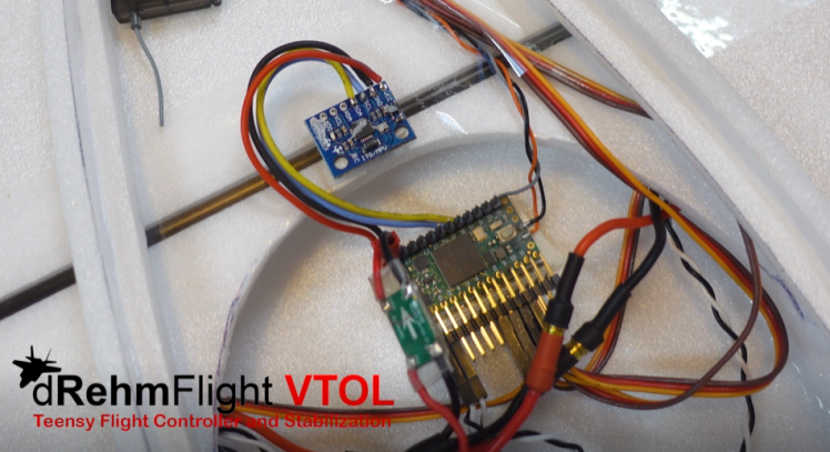
The stock dRehmflight code handled the roll and pitch angle stabilization with almost no modification--just to the control mixer function, where stabilized PID variables are assigned to the motor and servo outputs. Adding altitude hold capability took only a little more work to get integrated in the form of a new function and stabilized variable to assign out to the servos and motors:
- void controlAlt() {
- float alt_setpoint = 27.0; //desired altitude, cm
- float kP_alt = 0.8;
- float kI_alt = 0.35;
- float kD_alt = 0.2;
- float alt_int_max = 50.0; //integrator saturation limit
- float alt_error_max = 120.0; //cm
- float alt_beta = 0.15;
- //get the lidar data
- lidar.getData(tf_alt_raw, tf_trust, tf_temp);
- //filter the altitude data
- tf_alt_filtered = alt_beta*tf_alt_raw + (1.0 - alt_beta)*tf_alt_filtered;
- //get derivative
- tf_vel = (tf_alt_filtered - tf_alt_prev)/dt;
- tf_alt_prev = tf_alt_filtered;
- //PID controller
- float error_alt = alt_setpoint - tf_alt_filtered;
- error_alt = constrain(error_alt, -alt_error_max, alt_error_max);
- alt_integral = alt_integral + error_alt*dt;
- if (channel_1_pwm < 1060) { //set integral to zero at zero throttle
- alt_integral = 0.0;
- }
- alt_integral = constrain(alt_integral, -alt_int_max, alt_int_max); //saturate integral term to prevent wind up
- alt_PID = 0.01*(kP_alt*error_alt + kI_alt*alt_integral - kD_alt*tf_vel); //stabilized variable for altitude
- }
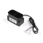
I used a TFMini plus lidar sensor for the altitude measurement, and the above code computes a stabilized PID variable based on a fixed altitude setpoint. This variable is assigned to the motors and servos in the dRehmFlight control mixer onboard the Teensy microcontroller:
- //Mode 3
- if (channel_6_pwm < 1300){ //switch down
- m1_command_scaled = thro_des + yaw_PID + thro_alt_mix_amount*alt_PID; //right motor
- m2_command_scaled = thro_des - yaw_PID + thro_alt_mix_amount*alt_PID; //left motor
- s1_command_scaled = RHS_ail_trim + ail_roll_amount*roll_PID - alt_PID; //right aileron
- s2_command_scaled = LHS_ail_trim + ail_roll_amount*roll_PID + alt_PID; //left aileron
- s3_command_scaled = RHS_elev_trim + elev_roll_amount*roll_PID - pitch_PID + elev_alt_mix_amount*alt_PID; //right elevon
- s4_command_scaled = LHS_elev_trim + elev_roll_amount*roll_PID + pitch_PID - elev_alt_mix_amount*alt_PID; //left elevon
- }
The majority of the work in maintaining altitude is done by the ailerons, or flaperons, which actuate up to reduce lift when the vehicle is too high, and down to produce lift when the vehicle is too low. I also mixed in a little motor response so that throttle would increase when too low, and decrease when too high.
Autonomy and Computer Vision
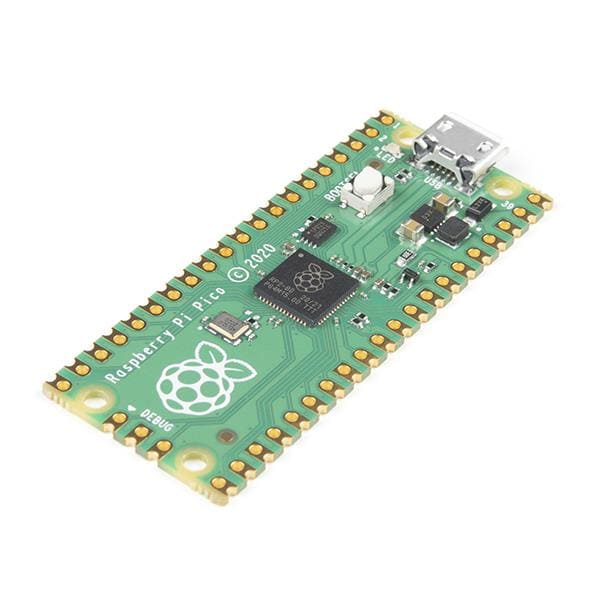
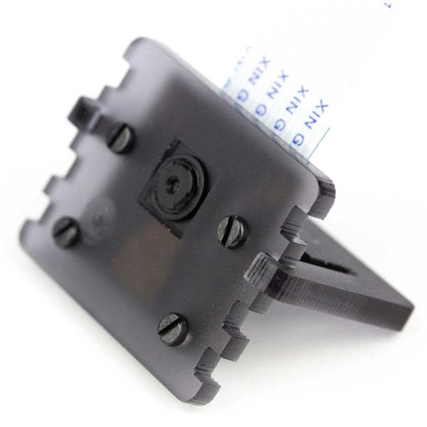
With all of that figured out and flying well, I finally had my Ekranoplan flying similarly to Think Flight's platform. Next up was to add computer vision so that it could track a tag placed on the back of whatever it is we want to follow. I used a Raspberry Pi 4b computer running Robot Operating System to run all of the image detection and autonomous control functionality. The pi was overclocked to squeeze out as much performance as possible, which was a fun balancing act that we'll discuss later. Along with the pi, an HD USB camera and separate Teensy microcontroller (pink!) made up the complete autonomy hardware package:
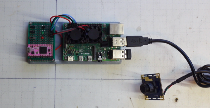
The thought process behind the pi and companion microcontroller needs a little explaining. The pi and camera handle the computer vision, target tracking, and control laws. Their control output is then fed to the microcontroller over a serial connection. The radio receiver on the Ekranoplan that normally plugs straight into the flight controller is instead connected to this microcontroller. The microcontroller reads in the receiver's PPM signal, adds on the autonomous commands from the pi, and spits out a new PPM signal to be sent to the flight controller. The main reason for this re-piping of radio control signal is because my flight controller is different than the flight controller Think Flight will be using to stabilize his 7ft Ekranoplan. By 'spoofing' radio command signals, the flight controller thinks it's being flown by a pilot on the ground. So regardless of which flight controller system you're using, the new flight computer we're adding is guaranteed to be compatible with it. Now, why not just let the pi do this spoofing of the radio control signal and avoid needing another microcontroller? The short answer is: a pi running an OS is prone to freezing or unanticipated performance fluctuation. The microcontroller guarantees that regardless of the health of the pi, the pilot's radio signals can still be piped through to the flight controller. This is important if the pilot needs to take over the aircraft at any time during the flight.
I used Apriltag markers as my target-to-track in this project, mainly because there's an easy to use ROS package available: http://wiki.ros.org/apriltag_ros
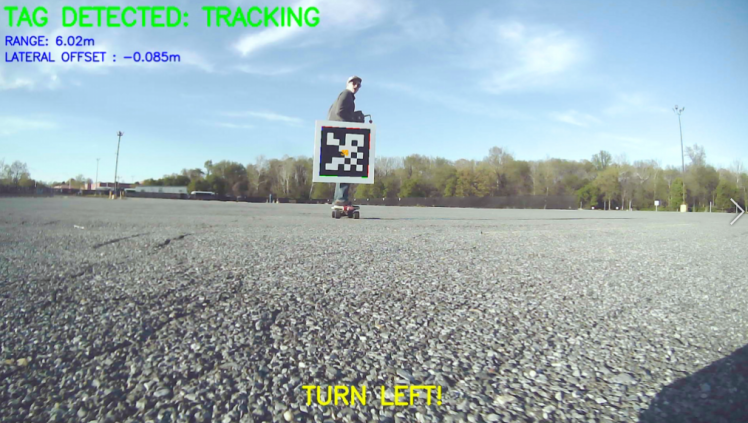
Not only is it easy to use, but it also gives excellent pose estimation of the tags that can be used in a controller to minimize tracking angle and desired follow distance error:
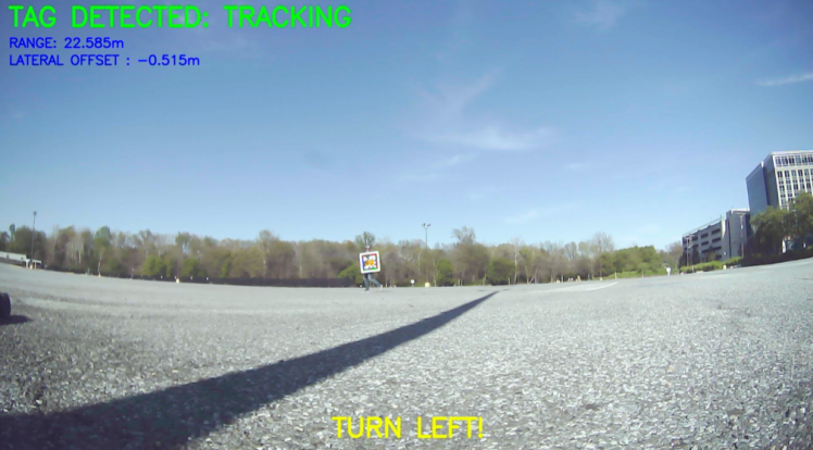
The ROS nodes to record onboard video, add the above overlay, compute the control output, and communicate with the microcontroller over serial all had to be written from scratch. Luckily, a lot of the heavy lifting had already been done from one of my previous projects where I implemented the Google Maps algorithm on my drone and let it fly through an obstacle course in my backyard: https://www.youtube.com/watch?v=p8frNNYQNV4
Results and Conclusions
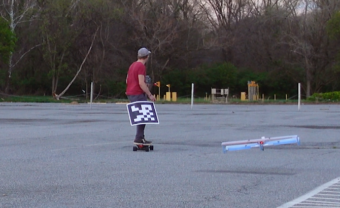
I don't have a boat to follow behind, so instead I printed out a huge Apriltag, taped it to my leg, and went for a ride on my electric longboard. It took a bit of tuning, but I eventually got it to follow behind me at a fixed distance pretty consistently.
One of the challenges in squeezing out as much tracking performance as possible was balancing the resolution of the onboard video and the computation speed of the pi. A larger video meant more pixels to detect the tags at a farther distance, but it also meant a lower framerate with the Apriltag pose extraction algorithm running at full steam. I found a balance at about 3fps that gave good detections at a distance and provided enough control bandwidth to close the loop on my Ekranoplan / electric longboard system. In reality for my side of the project, I could have gotten away with far lower video resolution for the distances I was dealing with in the small parking lot. But I was interested in testing the performance of my controller at the lower framerate, as this was the setup that would need to work at 150ft+ following behind Think Flight's boat.
Be sure to watch the video at the top to see how it flew! This was a fun project that needed a lot of individual components to play nicely together, and I'd be a liar if I said it all worked on the first try. The flight computer assembly is now on it's way to the West coast to be integrated and flown on Think Flight's platform in the coming weeks.
Cheers!
Code
Credits

Related products


Leave your feedback...