
Automatic Pet Water Chiller

Made by electrouser881 / Animals / Food & Drinks / Health / Sensors / Sustainability
About the project
Say goodbye to ice cubes and automatically cool your pet's water dish.
Items used in this project
Hardware components


View all
Story
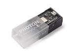
Using Thermo Electric Cooling technology, you too can cool your pet's water dish! With the rising temperatures, I know the best way to cool down your puppers is from the inside. Usually, I dropped some ice cubes into the water bowl, but now, I just leave this to check if the temperature is hot enough to warrant cooling. The Arduino and temperature sensor conserve power by not having the fan and Peltier running all the time. If you want, however, you can override the sensor and turn it on from your mobile phone thanks to a Particle! Photon This is an energy-efficient, pet-friendly way to automate part of your day, at least in the summer. The battery can be connected to a standard USB charger, so you could charge this with a wall socket, leave it plugged in, of even power it with a solar array! If you like animals and have been wanting to get into Arduino hardware and software projects, this is the project for you!
Let's get started!
Step 1: Materials
 1 / 6
1 / 6
For this project, you're going to need:
- Voltmeter
- 1 Peltier Module (TEC1-12706)
- 1 old computer fan with heatsink
- Thermal Pads
- 1 Aluminum Cooling Block
- 1 Arduino Uno
- 1 12v relay (that's what I had lying around but with a 5v relay you won't need a boost converter)
- 1 Diode
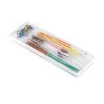
- 1 Breadboard
- Jumper Wires
- Wire Nuts
- USB Tail(USB with the phone connecter part cut off)
- Full USB Cable(for Arduino)
- Battery
The bolded things can be replaced with this kit I found on Amazon.
The italicized things can be replaced by the user's choice of power, though I recommend 5 volts of output(explanation in the end)
Step 2: Building the Cooling Element
; ; 1 / 6
1 / 6
First, cover your aluminum cooling block in thermal pads, thermal paste, or thermal grease. Don't put too much as it will hamper the heat transfer process. Now stick your Peltier module on it with the labelled side facing you.
Second, make sure your heatsink and fan combo works. Screw the fan onto the heatsink and turn it on. The bottom part of the heat sink should be a little bit cooler than the ambient, but not too much as the fan is just blowing air right now. If it works, go to the next step.
Last, coat the other side of the aluminum block and stick it on the heat sink. The Peltier side of this device will contact the underside or your pet's water bowl directly to cool it down(see last image for reference).
Now to the wiring.
Step 3: Wiring
; ; 1 / 7
1 / 7
First, hook up your fan and Peltier module in parallel and give them a single pair of input (power and ground) wires. You can do this by attaching both red(power) wires to a single red wire with a wire nut and doing the same for the black(ground) wires.We'll be feeding them 5v from here. Next, solder some wires into the two input and two output holes in the boost converter. I used jumper wires to make the booster breadboard friendly.
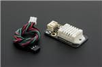
Second, orient your sensor so it is facing out from the Arduino as shown in the image. I found that if you twist the data pin of the sensor, it will fit right into the analog 0 pin when the power and ground pins are in their correct positions. You can choose to carefully bend the leg reducing the amount of wires needed, or hook it up on your breadboard using three jumper wires.
Third, place your booster on your breadboard as shown in the image. Place your relay closer to the output side of the boost converter. Remember to place these components on both halves of the breadboard to avoid a short-circuit. Connect a diode to serve as a flyback from the ground side of the relay coil to the power side. This is to protect is as voltage spikes from the motor could otherwise damage it. Connect the input power wire from your converter to pin 4 of the Uno and the input ground pin to ground. Using your voltmeter, configure the boost converter's output to be 11 volts. You'll do this by using a flathead screwdriver to turn the knob on the blue component. This should be enough to turn on your relay without damaging it. Connect the output power and ground pins to opposite sides of the coil in the relay (more on that later).
Fourth, squish your Particle Photon onto the side of your breadboard and connect it to your Arduino's Ground and Power pins. Now connect a pin (I used Analog 2) from the Photon to where the Arduino's Digital Pin 4 goes on the input side of the boost converter. This will be your manual override button in case you feel it is hot but the sensor says it isn't.
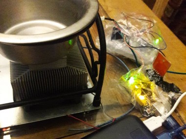
Last, take your USB tail and hook up the black wire to your combined Peltier/Fan ground input. Hook up the USB tail's red wire to the switch part of the relay. Now connect your Peltier/Fan power wire to the other side of that switch. Add a couple of plastic bags for water proofing in case of accidents and presto! My dish came with a little tray to keep it elevated, but you can make one yourself if you want.
Let's move on to the code, and then a bit of theory.
Step 4: Software
; ; 1 / 2
1 / 2
This is optional, but you can add an LED to the booster inputs to see if it is getting turned on by the Arduino.
I've uploaded my Arduino code so you can skip this text and just flash it onto your board if you want.
This script uses the dht Arduino library. In it, we assign the A0 pin as an input from the temperature sensor and Digital pin 4 as an output for the boost converter. The DHT library takes in the sensor's data and calculates the heat index, or how hot it feels, using temperature and humidity. This heat index can be used to set the minimum threshold for turning on the water chiller. I took a more liberal approach and set it to turn on if either the temperature or humidity are too high. If you want to customize it for your specific region, you would use those three factors for calibration.
Once you flash it onto your Arduino, plug your Arduino into your battery. If the temperature is high, the LED will turn on and you should hear a small click on your relay. Your fan will turn on and so will your Peltier. The bowl I was using cooled down to 50 degrees, but warmed up a bit when I added water. If your water is not cooling enough increase the voltage from your power source, but don't go over the maximum ratings of your Peltier or fan.
Use the default Blynk code for the Particle Photon, but don't forget to add your own Authorization token. On the Blynk app, make a button with A2 as an output pin. This will let you control the chiller from your phone.
Schematics, diagrams and documents
Code
Credits
Related products


Leave your feedback...