
Audio Vu Meter Using Arduino

About the project
A VU meter is a device that displays a description of the signal level in audio equipment.
Project info
Difficulty: Moderate
Platforms: Arduino
Estimated time: 1 day
License: GNU General Public License, version 3 or later (GPL3+)
Items used in this project
Hardware components


Story
A VU meter or standard volume indicator (SVI) is a device that displays a description of the signal level in audio equipment.
In this project, the intensity of left-channel and right-channel audio signals provided as input to the Arduino UNO board is presented as bars on the 16×2 LCD.
With the help of IoT Training Online, it is easy to learn all such IoT Applications in various industries.
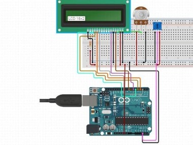
In this Arduino circuit, analog input pins of the Arduino UNO board are utilized for the measurement of audio-signal levels.
Audio-signal inputs are presented at analog input pin A2 and pin A4 of the Arduino UNO board. These can be in the order of voice coming from a microphone through an amplifier or as direct output from a music player.
Audio signals at pin A2 and pin A4 are prepared by ATmega328 microcontroller on the Arduino UNO board and after comparing the signals, estimations are done.
Finally, identical values are presented by ATmega328 to a 16×2 LCD for displaying audio intensity bars as shown in below implementation.
Arduino Audio VU Meter

The height of the bars will vary as per the voltage of the audio input signal at pins A2 and pin A4 of the Arduino UNO board. L is presented on the LCD for the left channel and similarly, R is presented for the right channel.
Connections of pin A2 and pin A4 of the Arduino UNO board must be done carefully so that proper channel audio input is presented to the circuit.
To present bars on the LCD screen, custom characters are designed for the 16×2 LCD, which is described in the programming section.
The Potentiometer is utilized for controlling the contrast of the display and so, can be modified as per requirement.
Code
Credits
Related products


Leave your feedback...