
Arduino: Using Photo Interrupter (slotted Optocoupler)

About the project
Connect and use Photo Interrupter (Slotted Optocoupler) in your Arduino projects - quick and easy.
Project info
Difficulty: Easy
Estimated time: 1 hour
License: GNU General Public License, version 3 or later (GPL3+)
Items used in this project

Software apps and online services
Story
Slotted Optocouplers (Photo Interrupters) are very useful sensors, often included in Arduino projects to detect position of moving objects, measure speed of rotation, or linear motion, frequency of events, and many others.
They are easy to use, but it is important to understand how they work, so you can get good results from them.
The optocouplers also come in different shapes, and while some are simple analog sensors, others have built in comparators such as LM393.
In this Tutorial, I will show you how you can connect the Optocoupler to Arduino, read the data as Analog or Digital, and if necessary convert the analog values to digital, and how to reduce noise from the sensor.
Step 1: Components
1 / 3 • Picture 1

Picture 1

Picture 2

Picture 3
- One Arduino compatible board (I use Arduino Nano, because I have one, but any other will be just fine)
- One simple Optocoupler Sensor module (Shown on the right on Picture 2 and 3) I got from this cheap 37 sensors set.I also show a more advanced bigger Optocoupler module with LM393 comparator that has both digital and analog outputs (Shown on the left on Picture 2 and 3).You can also use very much any other optocoupler module
- 3 Female-Female jumper wires
1 / 6 • Picture 1

Picture 1

Picture 2

Picture 3

Picture 4

Picture 5

Picture 6
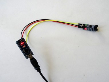
- Connect Ground(Black wire), Power(Red wire), and Signal(Yellow wire) to the Optocoupler Module(Picture 1 and 2) ( Pictures 3 and 4 show the more advanced sensor with its analog output connected )
- Connect the other end of the Ground wire(Black wire) to the Ground pin of the Arduino board (Picture 5)
- Connect the other end of the Power wire(Red wire) to the 5V power pin of the Arduino board (Picture 5)
- Connect the other end of the Signal wire(Yellow wire) to the Analog pin 0 of the Arduino board (Picture 5)
- Picture 6 shows where are the Ground, 5V Power, and Analog 0 pins of the Arduino Nano
1 / 2 • Picture 1

Picture 1

Picture 2
To start programming the Arduino, you will need to have the Arduino IDE installed from here: http://www.arduino.cc/.
Please be aware that there are some critical bugs in Arduino IDE 1.6.6.
Make sure that you install 1.6.7 or higher, otherwise this Tutorial will not work!
The Visuino: https://www.visuino.com also needs to be installed.
- Start Visuino as shown in the first picture
- Click on the "Tools" button on the Arduino component (Picture 1) in Visuino
- When the dialog appears, select "Arduino Nano" as shown in Picture 2
1 / 2 • Picture 1

Picture 1

Picture 2
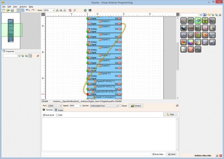
In Visuino connect the "Out" pin of the "Digital[ 14 ]/Analog[ 0 ]" channel of the Arduino component (Picture 1) to the "In" input pin of the "Serial[ 0 ]" channel of the Arduino component(Picture 2)
Step 5: Generate, Compile, and Upload the Arduino code
1 / 2 • Picture 1

Picture 1

Picture 2
- In Visuino, Press F9 or click on the button shown on Picture 1 to generate the Arduino code, and open the Arduino IDE
- In the Arduino IDE, click on the Upload button, to compile and upload the code (Picture 2)
1 / 5 • Picture 1

Picture 1

Picture 2

Picture 3

Picture 4

Picture 5
Picture 1 shows the running project.
Picture 2 shows the complete Visuino diagram.
In Visuino, select the serial port and click on the Connect button (Picture 3) . You should see the value of the optocoupler output printed on the Serial terminal (Picture 4)
If you switch to the Scope tab, you will see the data from the sensor plotted on the scope(Picture 5)
If you place an obstacle interrupting the light beam of the sensor, you will notice that the value is increasing. You may also notice that if you move the obstacle slowly to interrupt the beam, the value will also change somewhat slow. This is because we have connected the sensor to analog pin, and we are measuring the change of the light on the sensor. This is nice to do when we study how the sensor works, but is not that practical for detecting fast events. Continue with the next step to see different ways to detect properly when the beam is interrupted as a digital value.
Also attached is the Visuino project, that I created for this Tutorial. You can download and open it in Visuino: https://www.visuino.com
Step 7: In Visuino: Add and connect Compare Analog Value component
1 / 5 • Picture 1

Picture 1

Picture 2

Picture 3

Picture 4

Picture 5
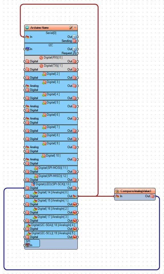
To really use the information from the optocoupler, you will need to convert it to digital boolean value. There are many ways in which this can be done. One of them is to use Compare Analog Value component and compare the signal to a value:
- Type "compa" in the Filter box of the Component Toolbox then select the "Compare Analog Value" component (Picture 1), and drop it in the design area
- Connect the "Out" pin of the "Digital[ 14 ]/Analog[ 0 ]" channel of the Arduino component to the "In" pin of the CompareAnalogValue1 component (Picture 2)
- Connect the "Out" pin of the CompareAnalogValue1 component to the "Digital" input pin of the "Digital[ 13 ]" channel of the Arduino component (Picture 3)
- In the Object Inspector, set the value of the "Compare Type" property of the CompareAnalogValue1 component to ctBigger (Picture 4)
- In the Object Inspector, set the value of the "Value" property of the CompareAnalogValue1 component to 0.5 (Picture 5)
- Generate, Compile, and Upload the Arduino code as you did in Step 5
- If you power the Arduino, and place obstacle to block the light beam of the sensor, the LED on Pin 13 of the Arduino board will turn on as seen on the video. If you remove the obstacle, the LED will turn off.
On the Picture you can see the complete Visuino diagram.
Also attached is the Visuino project, that I created for this Tutorial. You can download and open it in Visuino: https://www.visuino.com
Step 9: In Visuino: Add and connect Debounce Button component
1 / 3 • Picture 1

Picture 1

Picture 2

Picture 3
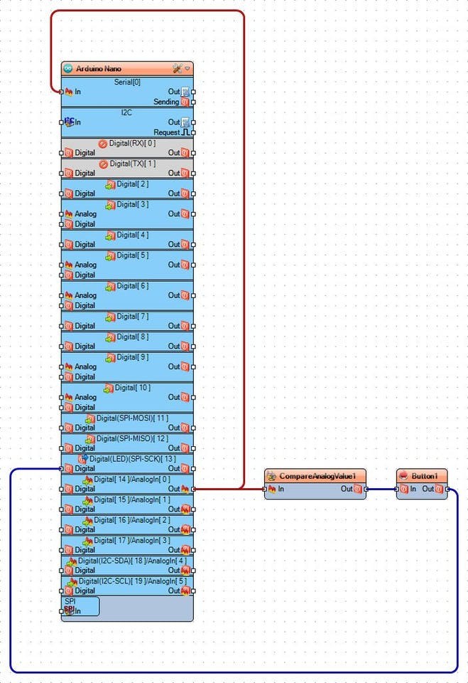
When using compare component to detect the change of level in the optocoupler there are cases when the signal will go briefly back and forth above and below the trigger level before settling to a stable level. This introduces a noise, and invalid data. This noise is similar to the bouncing noise when pressing or releasing button. Visuino includes a button debouncing component, which can also be used to suppress the noise from the optocoupler:
- Type "deb" in the Filter box of the Component Toolbox then select the "Debounce Button" component (Picture 1), and drop it in the design area
- Connect the "Out" pin of the CompareAnalogValue1 component to the "In" pin of the Button1 component (Picture 2)
- Connect the "Out" pin of the Button1 component to the "Digital" input pin of the "Digital[ 13 ]" channel of the Arduino component (Picture 3)
- Generate, Compile, and Upload the Arduino code as you did in Step 5
- If you power the Arduino, and place obstacle to block the light beam of the sensor, the LED on Pin 13 of the Arduino board will turn on as seen on the video. If you remove the obstacle, the LED will turn off.
On the Picture you can see the complete Visuino diagram.
Also attached is the Visuino project, that I created for this Tutorial. You can download and open it in Visuino: https://www.visuino.com
Step 11: In Visuino: Add and connect Schmitt Trigger component
1 / 4 • Picture 1

Picture 1

Picture 2

Picture 3

Picture 4
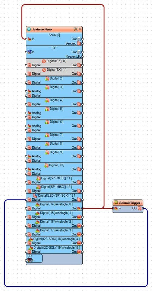
Another way to convert the analog value while reducing noise during the switching is to use Schmitt Trigger component with Hysteresis:
- Start with the original project where just the Analog 0 was connected to the Serial port.
- Type "schm" in the Filter box of the Component Toolbox then select the "Analog Schmitt Trigger (Hysteresis)" component (Picture 1), and drop it in the design area
- Connect the "Out" pin of the "Digital[ 14 ]/Analog[ 0 ]" channel of the Arduino component to the "In" pin of the SchmittTrigger1component (Picture 2)
- Connect the "Out" pin of the SchmittTrigger1 component to the "Digital" input pin of the "Digital[ 13 ]" channel of the Arduino component (Picture 3)
- Optionally, in the Object Inspector, change the values of the "Threshold" and the "Value" properties of the SchmittTrigger1 component (Picture 4)
- Generate, Compile, and Upload the Arduino code as you did in Step 5
- If you power the Arduino, and place obstacle to block the light beam of the sensor, the LED on Pin 13 of the Arduino board will turn on as seen on the video. If you remove the obstacle, the LED will turn off.
On the Picture you can see the complete Visuino diagram.
Also attached is the Visuino project, that I created for this Tutorial. You can download and open it in Visuino: https://www.visuino.com
Step 13: Connect the Optocoupler to the Digital 2 pin of Arduino
1 / 4 • Picture 1

Picture 1

Picture 2

Picture 3

Picture 4
The optocoupler can also be connected to a digital pin instead of analog pin. This will work both with simple optocoupler that provides analog signal as well as with optocoupler with onboard comparator such as LM393. The versions wit comparator will work much better as digital source than the simple ones.
- Disconnect the Signal wire(Yellow wire) from the Analog 0 pin of the Arduino board and connect it to the Digital pin 2 of the Arduino board (Picture 5)
- Optionally: If you use Optocoupler that has Digital output, you can connect the Signal wire(Yellow wire) to the Digital output (Pictures 2 and 3). This output is designed to provide more distinct switch between False and True
- Picture 4 shows where are the Ground, 5V Power(In Blue), and Digital 2(In Red) pins of the Arduino Nano
In Visuino connect the "Out" pin of the "Digital[ 2 ]" channel of the Arduino component to the "Digital" input pin of the "Digital[ 13 ]" channel of the Arduino component (as shown on the Picture)
Step 15: And play...
1 / 2 • Picture 1

Picture 1

Picture 2
- Generate, Compile, and Upload the Arduino code as you did in Step 5
- If you power the Arduino, and place obstacle to block the light beam of the sensor, the LED on Pin 13 of the Arduino board will turn on as seen on the video. If you remove the obstacle, the LED will turn off.
Picture 1 shows the completed and connected project with an optocoupler with digital output and LM393 comparator
On Picture 2 you can see the complete Visuino diagram.
Also attached is the Visuino project, that I created for this Tutorial. You can download and open it in Visuino: https://www.visuino.com
If you have some noise from the digital pin, you can also add Debounce Button component, the same way as it was done in Step 9 or in this Tutorial .
Credits
Related products


Leave your feedback...