
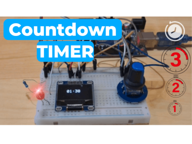
Arduino Oled Countdown Timer Using Visual Programming

Made by Ron / Clocks / Displays / Home Automation / Notifications / Sensors
About the project
Build a compact and practical OLED Countdown Timer using Arduino and Visual Programming in Visuino! Watch the Video!
Project info
Difficulty: Moderate
Platforms: Arduino, DFRobot, Seeed Studio, Visuino
Estimated time: 1 hour
License: GNU General Public License, version 3 or later (GPL3+)
Items used in this project
Hardware components

Story
Build a compact and practical OLED Countdown Timer using Arduino and Visual Programming in Visuino!
- Use a rotary encoder to set the countdown duration
- Start the timer by pressing the encoder button
- Watch the countdown update in real time on an OLED display
- Trigger a Red LED when the countdown reaches zero
All done with no coding, just simple drag-and-drop blocks in Visuino!
Perfect for beginners and makers looking for a practical timer easy to build.
Watch the Video!
Step 1: What You Will Need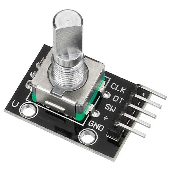
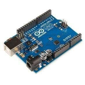
- Arduino UNO or any other Arduino board
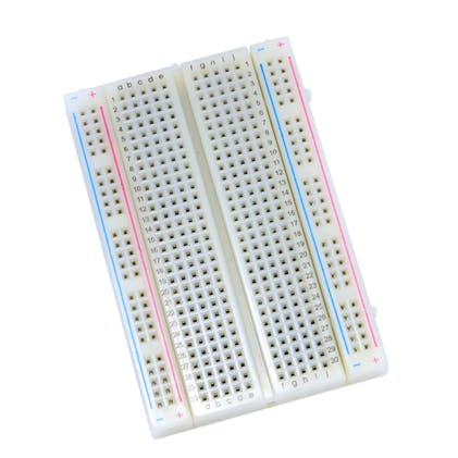
- Breadboard
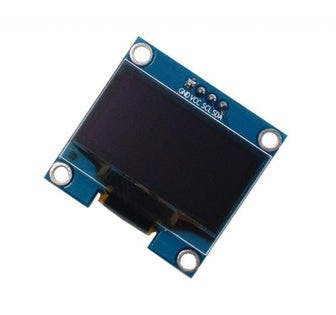
- OLED Display
- 1k ohm resistor
- LED
- Rotary encoder
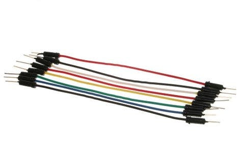
- Jumper wires
- Visuino software: Download here
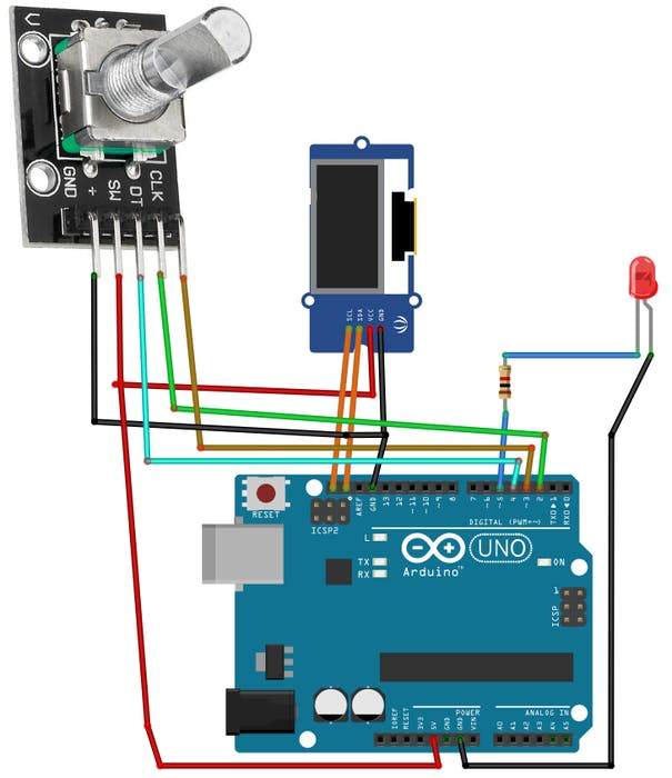
- Connect OLED Display pin [SCL] to Arduino pin [SCL]
- Connect OLED Display pin [SDA] to Arduino pin [SDA]
- Connect OLED Display pin [VCC] to Arduino pin [5V]
- Connect OLED Display pin [GND] to Arduino pin [GND]
- Connect Encoder pin [CLK] to Arduino pin [3]
- Connect Encoder pin [DT] to Arduino pin [2]
- Connect Encoder pin [SW] to Arduino pin [4]
- Connect Encoder pin [+ (VCC)] to Arduino pin [5V]
- Connect Encoder pin [GND] to Arduino pin [GND]
- Connect 220Ω resistor to Arduino pin [5]
- Connect anode (long leg) of Red LED to the resistor
- Connect cathode (short leg) of LED to Arduino [GND]
The Visuino: https://www.visuino.comalso needs to be installed.
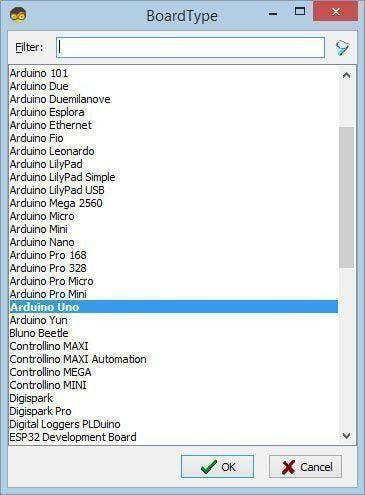
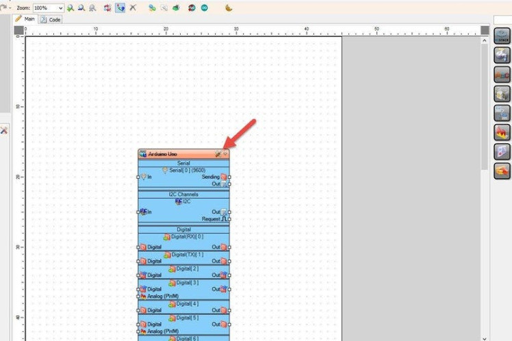
Start Visuino as shown in the first picture Click on the "Tools" button on the Arduino component (Picture 1) in Visuino When the dialog appears, select "Arduino UNO" as shown on Picture 2
Step 4: In Visuino Add Components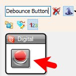
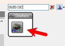

- Add "OLED I2C" component
- Add "Debounce Button" component
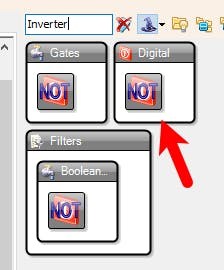
- Add "Digital (Boolean) Inverter (Not)" component
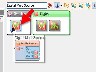
- Add 2X "Digital Multi Source" component
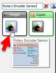
- Add "Rotary Encoder" component
- Add "Toggle(T) Flip-Flop" component
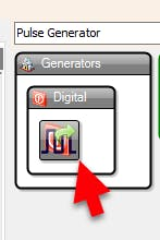
- Add "Pulse Generator" component
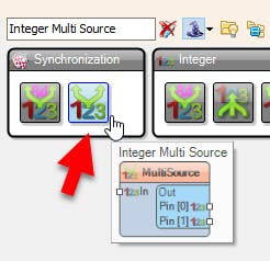
- Add 3X "Integer Multi Source" component
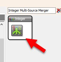
- Add 2X "Integer Multi-Source Merger" component
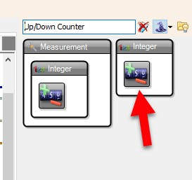
- Add "Up/Down Counter" component
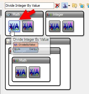
- Add "Divide Integer By Value" component
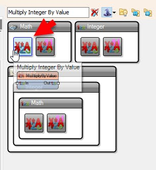
- Add "Multiply Integer By Value" component
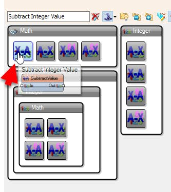
- Add "Subtract Integer Value" component
- Add "Formatted Text" component
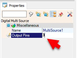
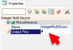
- Select "MultiSource1" and in the properties window set "Output Pins" to 3
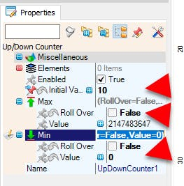
- Select "UpDownCounter1" and in the properties window select:"Initial Value" and set 10
- and set "Max > Roll Over" to False and "Min > Roll Over" to False and Min Value to 0.
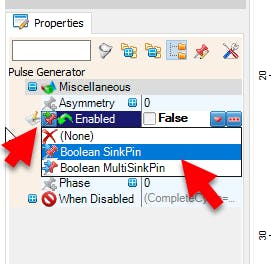
- Select "PulseGenerator1" and in the properties window Select "Enabled" and click on the pin icon and select "Boolean SinkPin" and set "Enabled" to False
- Select "MultiSource2" and in the properties window set "Output Pins" to 3
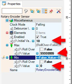
- Select "RotaryEncoderSensor1" and in the properties window select:"Initial Value" and set 10 and set "Max > Roll Over" to False and "Min > Roll Over" to False and Min Value to 0.
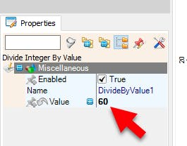
- Select "DivideByValue1" and in the properties window set Value to 60
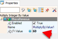
- Select "MultiplyByValue1" and in the properties window set Value to 60
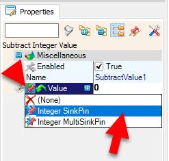
- Select "SubtractValue1" and in the properties window select Value and click on the Pin Icon and select "Integer SinkPin"
- Select "FormattedText1" and in the properties window set "Text" to: %0:%1
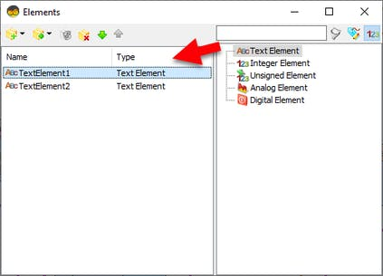
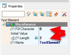
- Double click on "FormattedText1" and in the Elements window drag 2X "Text Element" to the left side and for both in the Properties window set "Fill Character" to 0 and "Length" to 2
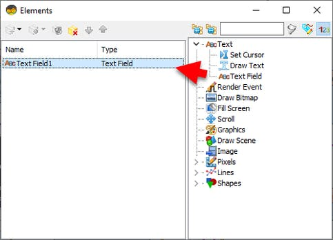
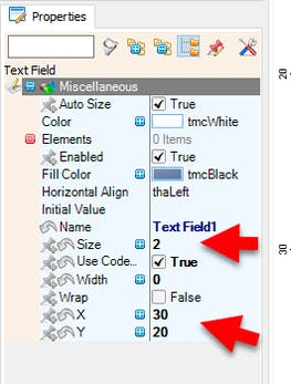
- Double click on "DisplayOLED1" and in the Elements window drag "Text Field" to the left side and in the properties window set "Size" to 2 "X" to 30 and "Y" to 20

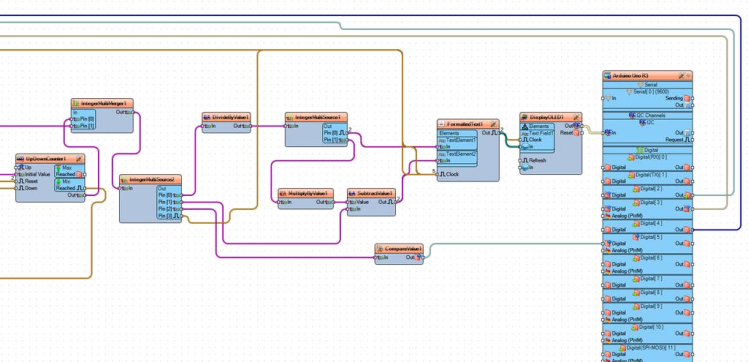
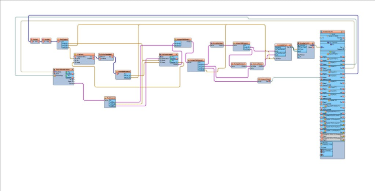
- Connect Arduino digital pin [2] to "RotaryEncoder1" pin Clock (A)
- Connect Arduino digital pin [3] to "RotaryEncoder1" pin Data (B)
- Connect Arduino digital pin [4] to "Button1" pin [In]
- Connect "Button1" pin [Out] to "Inverter1" pin [In]
- Connect "Inverter1" pin [Out] to "MultiSource1" pin [In]
- Connect "MultiSource1" pin [Out][0] to "UpDownCounter1" pin [Reset]
- Connect "MultiSource1" pin [Out][1] to "FormattedText1" pin [Clock]
- Connect "MultiSource1" pin [Out][2] to "TFlipFlop1" pin [Clock]
- Connect "DivideByValue1" pin [Out] to "IntegerMultiSource1" pin [In]
- Connect "IntegerMultiSource1" pin [Out][0] to "FormattedText1" pin [Clock]
- Connect "IntegerMultiSource1" pin [Out][0] to "FormattedText1" > "TextElement1" pin [In]
- Connect "IntegerMultiSource1" pin [Out][1] to "MultiplyByValue1" pin [In]
- Connect "MultiplyByValue1" pin [Out] to "SubtractValue1" pin [Value]
- Connect "SubtractValue1" pin [Out] to "FormattedText1" pin [Clock]
- Connect "SubtractValue1" pin [Out] to "FormattedText1" > "TextElement2" pin [In]
- Connect "FormattedText1" pin [Out] to "DisplayOLED1" > "Text Field1" pin [Clock]
- Connect "FormattedText1" pin [Out] to "DisplayOLED1" > "Text Field1" pin [In]
- Connect "DisplayOLED1" pin [Out] to "Arduino" > "I2C" pin [In]
- Connect "UpDownCounter1" pin [Out] to "IntegerMultiMerger1" pin [In][0]
- Connect "IntegerMultiMerger1" pin [Out] to "IntegerMultiSource2" pin [In]
- Connect "IntegerMultiSource2" pin [Out][0] to "DivideByValue1" pin [In]
- Connect "IntegerMultiSource2" pin [Out][1] to "SubtractValue1" pin [In]
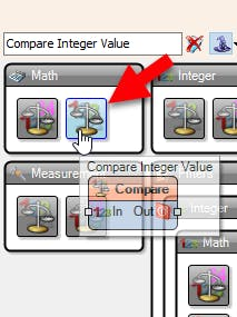
- Connect "IntegerMultiSource2" pin [Out][2] to "CompareValue1" pin [In]
- Connect "IntegerMultiSource2" pin [Out][3] to "FormattedText1" pin [Clock]
- Connect "CompareValue1" pin [Out] to "Arduino" digital pin [5]
- Connect "PulseGenerator1" pin [Out] to "DigitalMultiSource1" pin [In]
- Connect "DigitalMultiSource1" pin [Out][0] to "UpDownCounter1" pin [Down]
- Connect "DigitalMultiSource1" pin [Out][1] to "FormattedText1" pin [Clock]
- Connect "RotaryEncoderSensor1" pin [Out] to "MultiSource2" pin [In]
- Connect "MultiSource2" pin [Out][0] to "IntegerMultiMerger1" pin [In][1]
- Connect "MultiSource2" pin [Out][1] to "UpDownCounter1" pin [Reset]
- Connect "MultiSource2" pin [Out][2] to "UpDownCounter1" pin [InitialValue]
- Connect "TFlipFlop1" pin [Out] to "PulseGenerator1" pin [Enabled]
- Connect "UpDownCounter1" pin [MinReached] to "TFlipFlop1" pin [Reset]
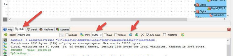
In Visuino, at the bottom click on the "Build" Tab, make sure the correct port is selected, then click on the "Compile/Build and Upload" button.
Step 8: PlayWhen you power on the Arduino, the OLED display will show the default countdown time of 00:10.
You can easily adjust the countdown time by rotating the rotary encoder left or right. Once you've set your desired time, simply press the encoder button to start the countdown.
During the countdown, you can pause or resume at any time by pressing the button again.
When the countdown reaches zero, a red LED will turn ON to signal that the time is up.
Congratulations! You have completed your project with Visuino. Also attached is the Visuino project, that I created for this Instructable, you can download it and open it in Visuino: https://www.visuino.com
Schematics, diagrams and documents
Code
Credits
Related products


Leave your feedback...