
Arduino Nano: Hmc5883l Compass With Visuino

About the project
Connect HMC5883L I2C Compass to Arduino, and program it quick and easy!
Project info
Difficulty: Easy
Estimated time: 1 hour
License: GNU General Public License, version 3 or later (GPL3+)
Items used in this project

Software apps and online services
Story
HMC5883L are popular Compass sensors. They can be used for navigation systems, drones, and robots.
In this Tutorial, I will show you how easy it is to program Arduino to use HMC5883L Compass with Visuino - an easy to use graphical development environment for Arduino.
Step 1: Components
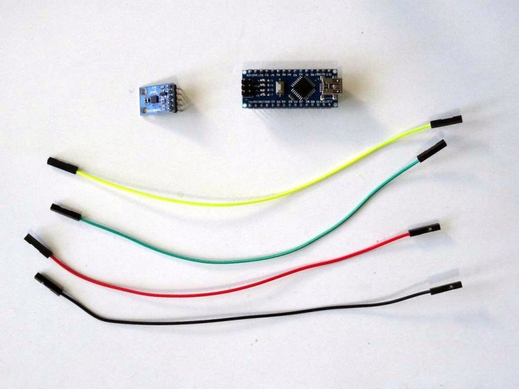
- One Arduino compatible board (I use Arduino Nano, because I have one, but any other will be just fine)
- One HMC5883L Compass Module
- 4 Female-Female jumper wires
1 / 3
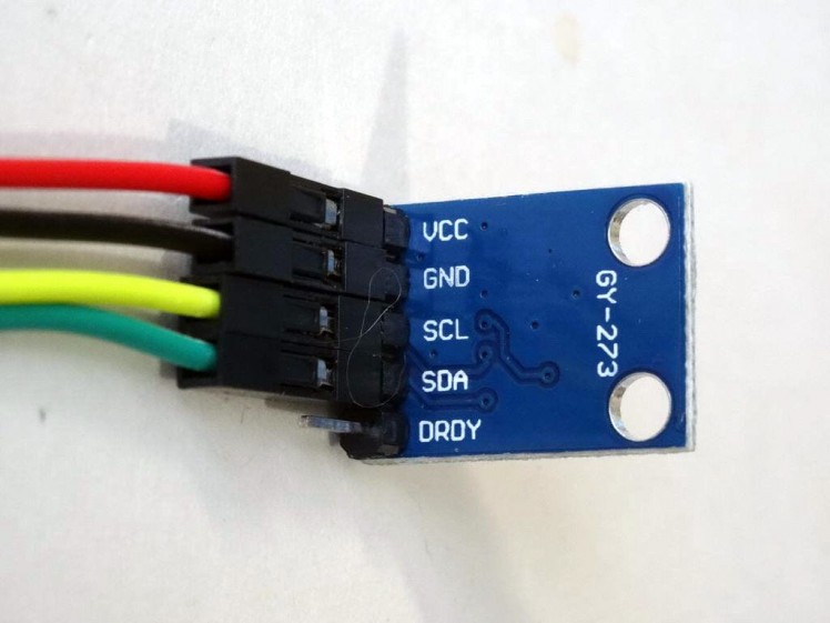
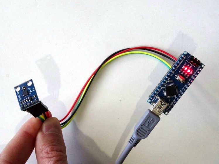
- Connect 5V VCC Power (red wire), Ground (black wire), SCL (yellow wire), and SDA (green wire), to the HMC5883L Compass Module (Picture 1)
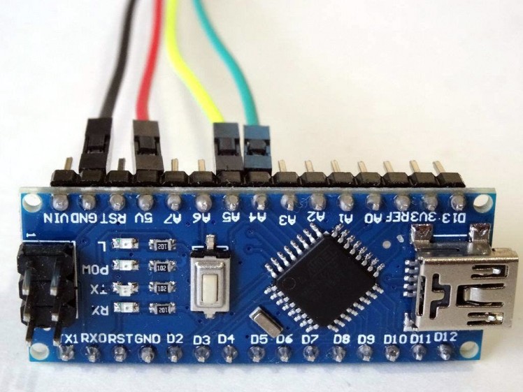
- Connect the other end of the Ground wire (black wire) to Ground pin of the Arduino board (Picture 2)
- Connect the other end of the 5V VCC Power wire (red wire) to the 5V power pin of the Arduino board (Picture 2)
- Connect the other end of the SDA wire (green wire) to SDA/Analog pin 4 of the Arduino Nano board (Picture 2)
- Connect the other end of the SCL wire (yellow wire) to SCL/Analog pin 5 of the Arduino Nano board (Picture 2)
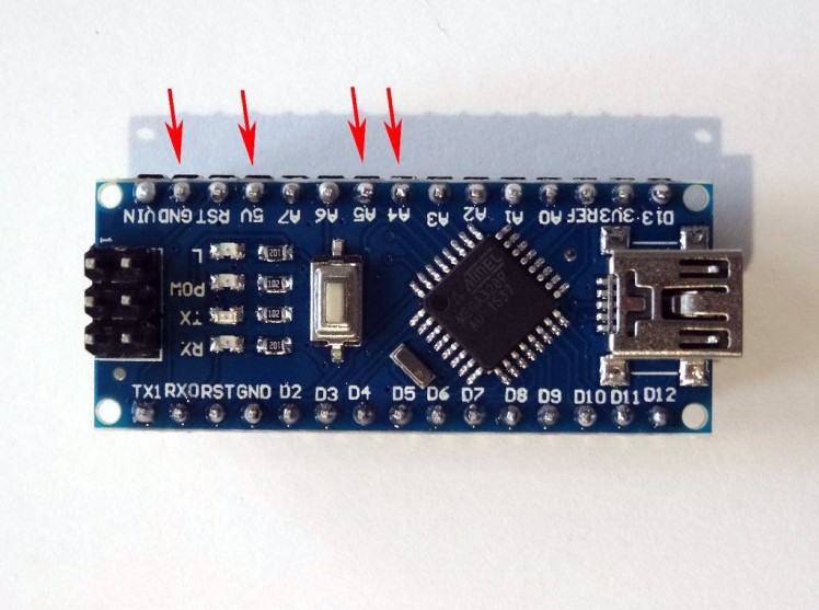
- Picture 3 shows where the Ground, 5VPower, SDA/Analog pin 4, and SCL/Analog pin 5 pins of the Arduino Nano are.
1 / 2
To start programming the Arduino, you will need to have the Arduino IDE installed from here: http://www.arduino.cc/.
Please be aware that there are some critical bugs in Arduino IDE 1.6.6.
Make sure that you install 1.6.7 or higher, otherwise this Tutorial will not work!
The Visuino: https://www.visuino.com also needs to be installed.
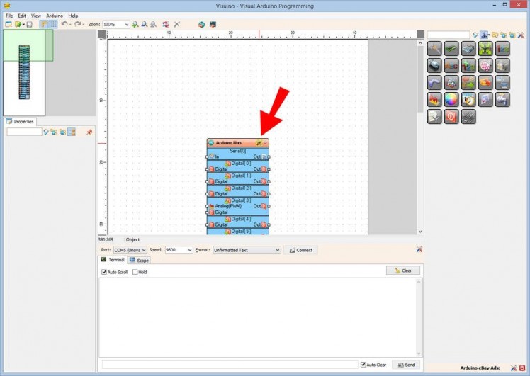
- Start Visuino as shown in the first picture
- Click on the "Tools" button on the Arduino component (Picture 1) in Visuino
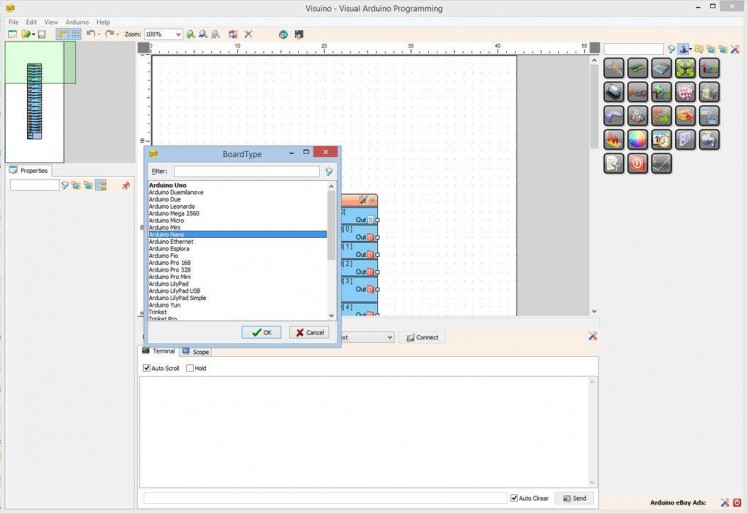
- When the dialog appears, select "Arduino Nano" as shown in Picture 2
1 / 3
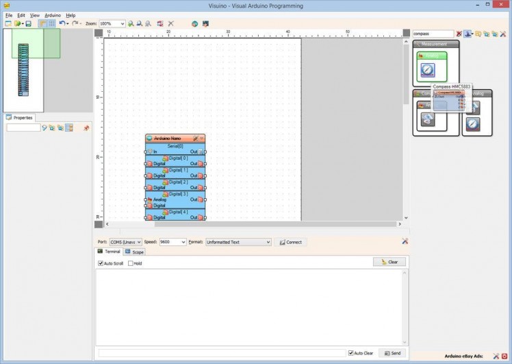
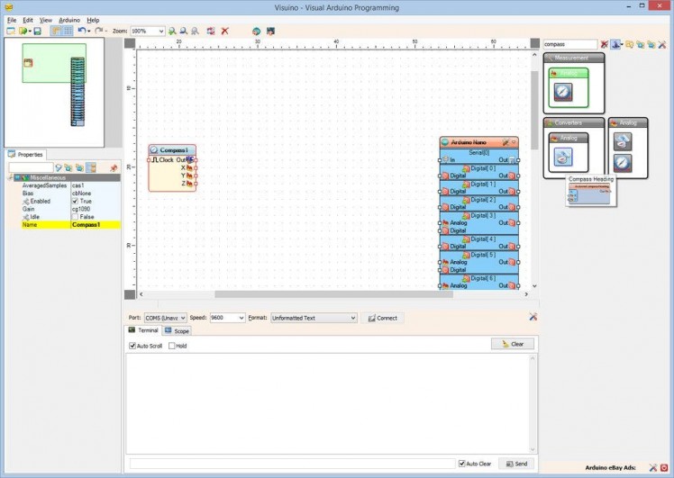
- Type "compass" in the Filter box of the Component Toolbox then select the "Compass HMC5883" component (Picture 1), and drop it in the design area
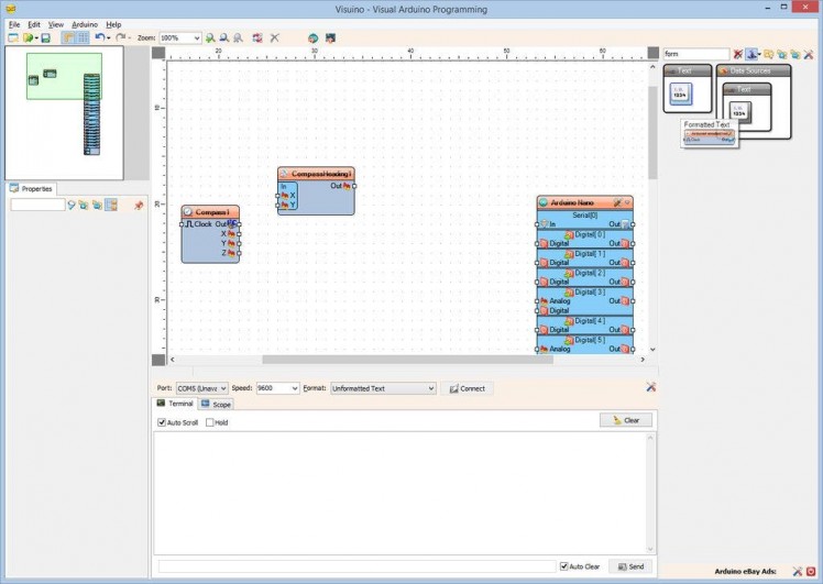
- From the Component Toolbox select the "Compass Heading" component (Picture 2), and drop it in the design area
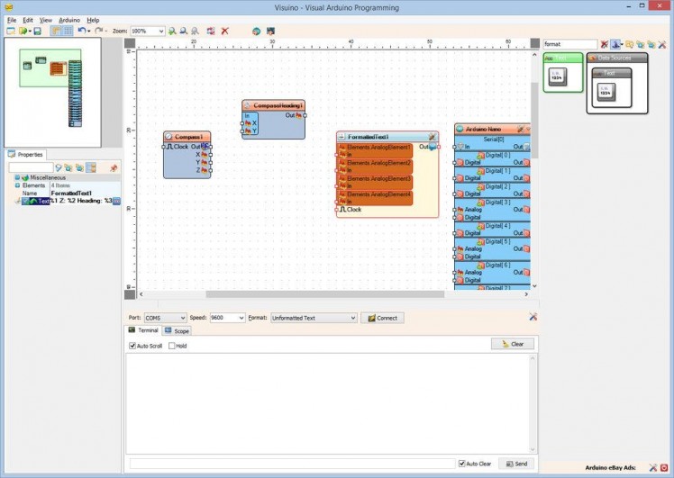
- Type "form" in the Filter box of the Component Toolbox then select the "Formatted Text" component (Picture 3), and drop it in the design area
1 / 4
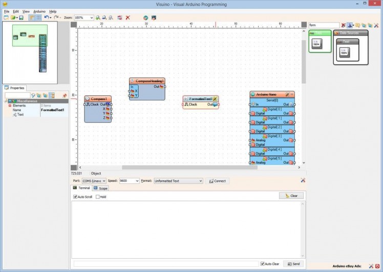
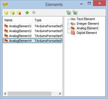
- Click on the "Tools" button of the FormattedText1 component
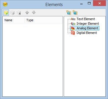
- In the Elements editor, Select the Analog Element on the right, and click 4 times on the "+" button on the left on the to add 4 of them (Picture 2, 3), then close the Elements editor
- Set the value of the Text property of the FormattedText1 component to "X: %0 Y: %1 Z: %2 Heading: %3" (Picture 4). The %0 will be replaced with the value from AnalogElement1, %1 will be replaced with the value from AnalogElement2, %2 will be replaced with the value from AnalogElement3, and %3 will be replaced with the value from AnalogElement4
1 / 4
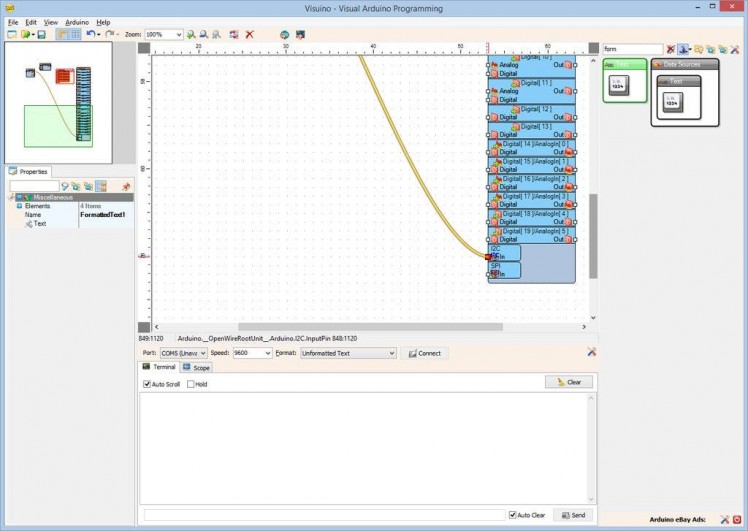
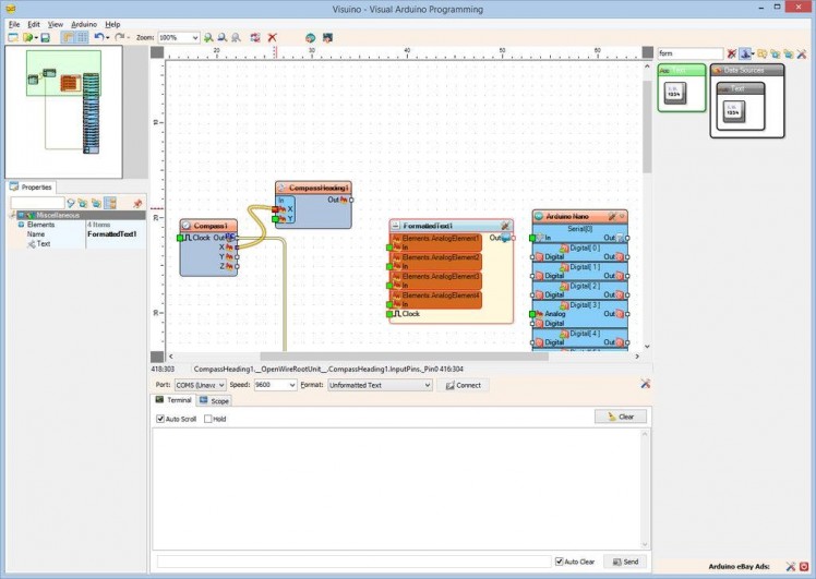
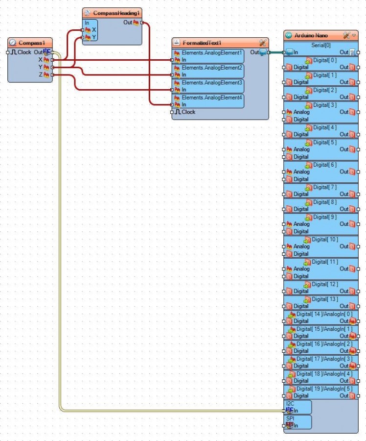
- Connect the "Out" pin of the Compass1 component (Picture 1) to the to the "In" pin of the I2C channel of the Arduino component (Picture 2)
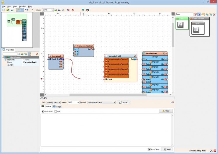
- Connect the "X" output pin of the Compass1 component to the "X" pin of the "In" pins of the CompassHeading1 component (Picture 3)
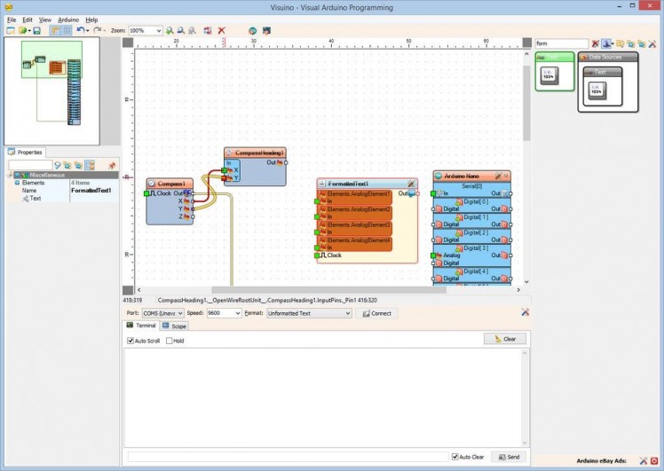
- Connect the "Y" output pin of the Compass1 component to the "Y" pin of the "In" pins of the CompassHeading1 component (Picture 4)
1 / 5
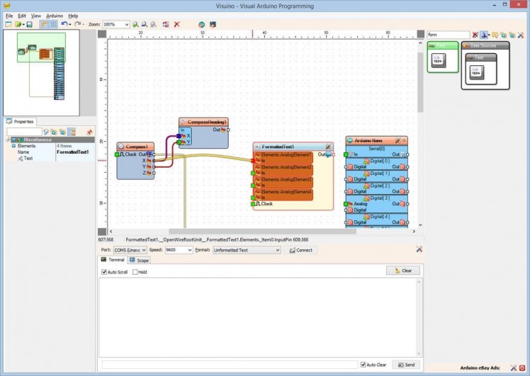


- Connect the "X" output pin of the Compass1 component to the "In" pin of the AnalogElement1 of the FormattedText1 component (Picture 1)
- Connect the "Y" output pin of the Compass1 component to the "In" pin of the AnalogElement2 of the FormattedText1 component (Picture 2)
- Connect the "Z" output pin of the Compass1 component to the "In" pin of the AnalogElement3 of the FormattedText1 component (Picture 3)
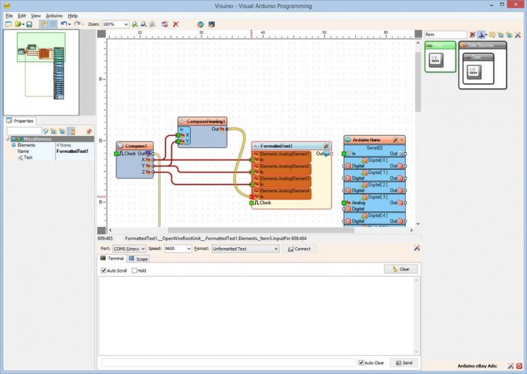
- Connect the "Out" output pin of the CompassHeading1 component to the "In" pin of the AnalogElement4 of the FormattedText1 component (Picture 4)
- Connect the "Out" output pin of the FormattedText1 component to the "In" input pin of the "Serial[ 0 ]" channel of the Arduino component (Picture 5)
1 / 2
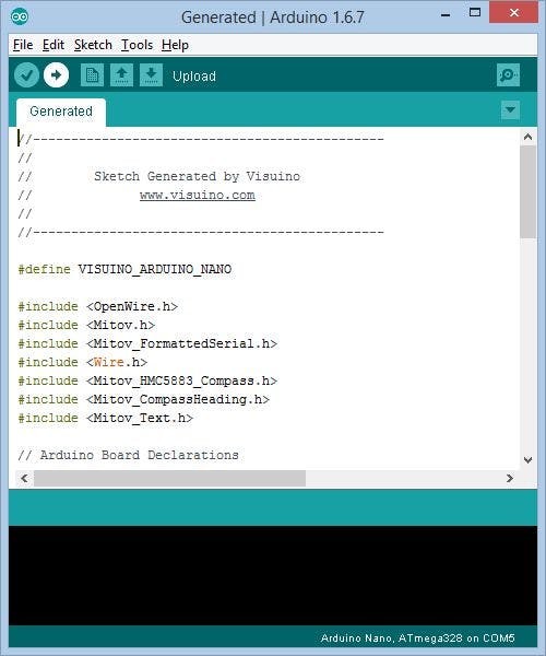
- In Visuino, Press F9 or click on the button shown on Picture 1 to generate the Arduino code, and open the Arduino IDE
- In the Arduino IDE, click on the Upload button, to compile and upload the code (Picture 2)
1 / 3
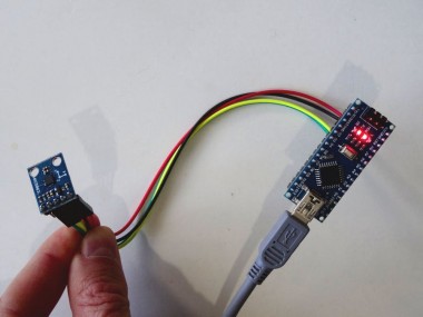
Congratulations! You have completed the project.
Picture 1 shows the connected and powered up project.
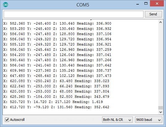
If you open Serial Terminal in the Arduino IDE or Visuino, you will see the X, Y, and Z magnetic values, as well as the calculated X,Y heading in degrees (Picture 2)
On Picture 3 you can see the complete Visuino diagram.Also attached is the Visuino project that I created for this Tutorial. You can download and open it in Visuino: https://www.visuino.com
Credits
Related products


Leave your feedback...