
Arduino Nano And Visuino: Infrared Remote Controlled Relay

About the project
Control a relay connected to Arduino with an infrared remote - quick and easy.
Project info
Difficulty: Easy
Estimated time: 1 hour
License: GNU General Public License, version 3 or later (GPL3+)
Items used in this project

Software apps and online services
Story
Recently I posted tutorial on how to connect Infrared Receiver Module to Arduino and program it with Visuino to decode and print the infrared codes in Serial Monitor. Soon after that people started to ask how to control Relay with it, so I decided to make this Tutorial.
In this tutorial I will show you how easy it is to connect Infrared Receiver and Relay Modules to Arduino and program it with Visuino to control the relay with a button on the Infrared Remote.
Step 1: Components
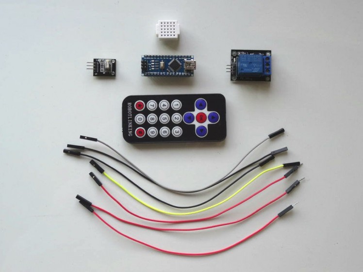
- One Arduino compatible board (I use Arduino Nano, because I have one, but any other will be just fine )
- One Digital Infrared Receiver Module I got from this cheap 37 sensors set.
- One Relay Module I got from this cheap 37 sensors set.
- One Infrared Remote - I got my one form an Arduino Robot KIT donated by Elegoo but you can use very much any remote from a TV, VCR, DVD/CD Player or anything else. My one uses NEC protocol but the project should work with other protocols as well.
- One small Breadboard (Any breadboard can be used, or any other way to connect 3 wires together)
- 4 Female-Female jumper wires
- 3 Female-Male jumper wires (Red)
1 / 4 • Picture 1

Picture 1

Picture 2

Picture 3

Picture 4
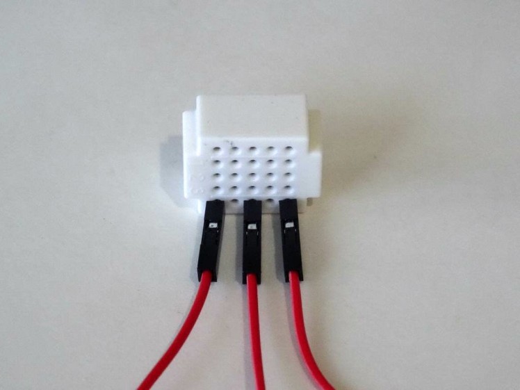
- Connect the Female end of a Female-Male wire (Red wire), to the Power pin of the Infrared Receiver Sensor Module (Picture 1)
- Connect Female-Female Ground(Black wire), and Data(Gray wire) to the Infrared Receiver Sensor Module (Picture 1)
- Connect the Female end of a Female-Male wire(Red wire) to the 5V power pin of the Arduino board (Picture 2)
- Connect the other end of the Ground wire(Black wire) to Ground pin of the Arduino board (Picture 2)
- Connect the other end of the Data wire(Gray wire) to Digital pin 2 of the Arduino board (Picture 3)
- Picture 4 shows where are the Ground, 5V Power, and Digital 2 pins of the Arduino Nano.
1 / 6 • Picture 1

Picture 1

Picture 2

Picture 3

Picture 4

Picture 5
- Connect the Female end of a Female-Male wire (Red wire), to the Power pin of the Relay Module (Picture 1 and 2)
- Connect Female-Female Ground(Black wire), and Control(Yellow wire) to the Relay Module (Picture 1 and 2)
- Connect the other end of the Ground wire(Black wire) to Ground pin of the Arduino board (Picture 3)
- Connect the other end of the Control wire(Yellow wire) to Digital pin 3 of the Arduino board (Picture 4)
- Picture 5 shows In Red where are the Ground, and Digital 3 pins of the Arduino Nano(In Blue are shown the pins connected in the previous step)
- Connect the Male ends of the 3 Power wires(Red wires) - from the Infrared Receiver, the Relay Module, and the Arduino together as example with the help of a Breadboard (Picture 1) - In my case I used a small breadboard
1 / 2 • Picture 1

Picture 1

Picture 2
To start programming the Arduino, you will need to have the Arduino IDE installed from here: http://www.arduino.cc/.
Make sure that you install 1.6.7 or higher, otherwise this Tutorial will not work!
The Visuino: https://www.visuino.com also needs to be installed.
- Start Visuino as shown in the first picture
- Click on the "Tools" button on the Arduino component (Picture 1) in Visuino
- When the dialog appears, select "Arduino Nano" as shown in Picture 2
1 / 4 • Picture 1

Picture 1

Picture 2

Picture 3

Picture 4
To decode the infrared commands, we will add Infrared Receiver component. The simplest way to decode a specific command is to add Decode element to the Infrared Receiver Elements:
- Type "infra" in the Filter box of the Component Toolbox then select the "Infrared Receiver" component (Picture 1), and drop it in the design area
- Click on the "Tools" button of the InfraredReceiver1 component to open the "Elements" dialog (Picture 2)
- In the "Elements" editor select the "Decode NEC Command" in the right window, and clicking on the "+" button (Picture 2) (My remote is NEC so used the NEC decode element. You may need to add a different element)
- In the Object Inspector set the value of the "Value" property of the element to "16712445" (Picture 4) - This will specify the Infrared button code (You may need to specify a different number if you use different remote or button)
- Close the "Elements" editor
1 / 4 • Picture 1

Picture 1

Picture 2

Picture 3

Picture 4
To implement the Toggle functionality, we need to use a Flip-Flop. The most convenient for this purpose is the Toggle(T)-FlipFlop.
- Type "flip" in the Filter box of the Component Toolbox then select the "Toggle(T) Flip-Flop" component (Picture 1), and drop it in the design area
- Connect the "Out" output pin of the "Digital[ 2 ]" channel of the Arduino component to the "Sensor" input pin of the InfraredReceiver1 component (Picture 2)
- Connect the "Out" output pin of the "Elements.Decode NEC Command1" element of the InfraredReceiver1 component to the "Clock" input pin of the TFlipFlop1component (Picture 3)
- Connect the "Out" output pin of the TFlipFlop1 component to the "Digital" input pin of the "Digital[ 3 ]" channel of the Arduino component (Picture 4)
1 / 2 • Picture 1

Picture 1

Picture 2
- In Visuino, Press F9 or click on the button shown on Picture 1 to generate the Arduino code, and open the Arduino IDE
- In the Arduino IDE, click on the Upload button, to compile and upload the code (Picture 2)
If you get compiler error in the Arduino IDE, this means that you are missing the following library:
https://github.com/z3t0/Arduino-IRremote
Look at this tutorial to see how to install it!
Step 8: And play...
1 / 2 • Picture 1

Picture 1

Picture 2
On Picture 1 you can see the complete Visuino diagram.
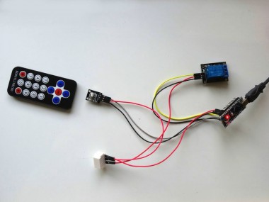
On Picture 2, and in the Video, you can see the completed and running project.
If you point the infrared remote to the sensor start pressing the OK button, as seen in the Video, the relay will turn On and Off on every button press
Congratulations! You have learned how to connect Infrared Remote Receiver to Arduino, and how to program it with Visuino to control a Relay.
Also attached is the Visuino project, that I created for this tutorial. You can download and open it in Visuino: https://www.visuino.com
Code
Credits
Related products


Leave your feedback...