
Arduino: Gps Display Location On I2c 2x16 Lcd With Visuino

About the project
Build GPS Location LCD Display with Arduino and program it - quick and easy!
Project info
Difficulty: Easy
Estimated time: 1 hour
License: GNU General Public License, version 3 or later (GPL3+)
Items used in this project

Software apps and online services
Story
Few days ago somebody asked me to make a tutorial on how to show GPS Latitude, and Longitude on a LCD Display. I promised to make one, and here it is.
In this tutorial, I will show you how you can connect Serial GPS Module, and I2C LCD Display to Arduino Nano, and show the location data from the GPS on the LCD.
Please note that since the Arduino Nano has only one Serial Port and it is used to program the board, you will need to program the Arduino before you connect the Serial GPS Module!
Step 1: Components
1 / 2 • Picture 1

Picture 1

Picture 2
- One Arduino compatible board (I use Arduino Nano, because I have one, but any other will be just fine)
- One GPS module
- One I2C 16x2 LCD Display (Back side of the LCD with the I2C adapter showed on Picture 2)
- One small Breadboard (Any breadboard can be used, or any other way to connect 3 wires together)
- 3 Female-Male jumper wires
- 5 Female-Female jumper wires
1 / 2 • Picture 1

Picture 1

Picture 2
Since the Arduino Nano has only one Serial port, and it is needed to program the Arduino, you will need to program the Arduino Nano before the GPS is connected.
To start programming the Arduino, you will need to have the Arduino IDE installed from here: http://www.arduino.cc/ .
Please be aware that there are some critical bugs in Arduino IDE 1.6.6.
Make sure that you install 1.6.7 or higher, otherwise this Tutorial will not work!
The Visuino: https://www.visuino.com also needs to be installed.
- Start Visuino as shown in the first picture
- Click on the "Tools" button on the Arduino component (Picture 1) in Visuino
- When the dialog appears, select Arduino Nano as shown in Picture 2
1 / 4 • Picture 1

Picture 1

Picture 2

Picture 3

Picture 4
- Type "GPS" in the Filter box of the Component Toolbox then select the "Serial GPS" component (Picture 1), and drop it in the design area
- Connect the "Out" pin of the LCD component to the to the "In" pin of the "Serial[ 0 ]" of the Arduino component (Picture 2)
- Type "lcd" in the Filter box of the Component Toolbox then select the "Liquid Crystal Display (LCD) - I2C" component (Picture 3), and drop it in the design area
- Connect the "Out" pin of the LCD component to the to the "In" pin of the "I2C channel" of the Arduino component (Picture 4)
1 / 6 • Picture 1

Picture 1

Picture 2

Picture 3

Picture 4

Picture 5

Picture 6
We will add a Text field with the description of the value, and Analog field to display the value for the Latitude and Longitude values.
First we will add Description and value fields for the Latitude:
- Click on the "Tools" button (Picture 1) to open the "Elements" editor (Picture 2)
- In the "Elements" editor select the "Text Field" in the right window, and click on the "" button on the left (Picture 2)
- In the Object Inspector set the value of the "Initial Value" property of the element to "Lat. :" (Picture 3)
- Select the "Analog Field" in the right window of the "Elements" editor, and clicking on the "" button on the left (Picture 4)
- In the Object Inspector set the value of the "Column" property of the element to "7" (Picture 5)
- In the Object Inspector set the value of the "Width" property of the element to "8" (Picture 6)
1 / 3 • Picture 1

Picture 1

Picture 2

Picture 3
Next we will add Description for the Longitude:
- In the "Elements" editor select the "Text Field" in the right window, and click on the "" button on the left (Picture 1)
- In the Object Inspector set the value of the "Initial Value" property of the element to "Long.: " (Picture 2)
- In the Object Inspector set the value of the "Row" property of the element to "1" (Picture 3)
1 / 4 • Picture 1

Picture 1

Picture 2

Picture 3

Picture 4
Next we will add Analog Element to display the value for the Longitude:
- Select the "Analog Field" in the right window of the "Elements" editor, and clicking on the "" button on the left (Picture 1)
- In the Object Inspector set the value of the "Column" property of the element to "7" (Picture 2)
- In the Object Inspector set the value of the "Row" property of the element to "1" (Picture 3)
- In the Object Inspector set the value of the "Width" property of the element to "8" (Picture 4)
- Close the "Elements" dialog
1 / 2 • Picture 1

Picture 1

Picture 2
- Connect the "Latitude" output pin of the "Location" box of the GPS1 component to the "In" pin of the Elements.AnalogField1 element of the LiquidCrystalDisplay1 component (Picture 1)
- Connect the "Longitude" output pin of the "Location" box of the GPS1 component to the "In" pin of the Elements.AnalogField2 element of the LiquidCrystalDisplay1 component (Picture 2)
1 / 2 • Picture 1

Picture 1

Picture 2
- In Visuino, Press F9 or click on the button shown on Picture 1 to generate the Arduino code, and open the Arduino IDE
- In the Arduino IDE, click on the Upload button, to compile and upload the code (Picture 2)
1 / 3 • Picture 1

Picture 1

Picture 2

Picture 3
Once the Arduino Nano is programmed, it is time to connect the hardware:
- Connect Ground (Black wire), Power (Red wire), SDA (Green wire), and SCL (Yellow wire) to the LCD Module (Picture 1)
- Connect the other end of the Ground wire (Black wire) to Ground pin of the Arduino board (Picture 2)
- Connect the other end of the SDA wire (Green wire) to SDA/Analog pin 4 of the Arduino Nano board (Picture 2)
- Connect the other end of the SCL wire (Yellow wire) to SCL/Analog pin 5 of the Arduino Nano board (Picture 2)
- Connect another Female-Male Power wire (Red wire) to the 5V Power pin of the Arduino board (Picture 2), and leave the Male end unconnected
- Picture 3 shows where are the Ground, 5V Power, SDA/Analog pin 4, and SCL/Analog pin 5 pins of the Arduino Nano
1 / 3 • Picture 1

Picture 1

Picture 2

Picture 3
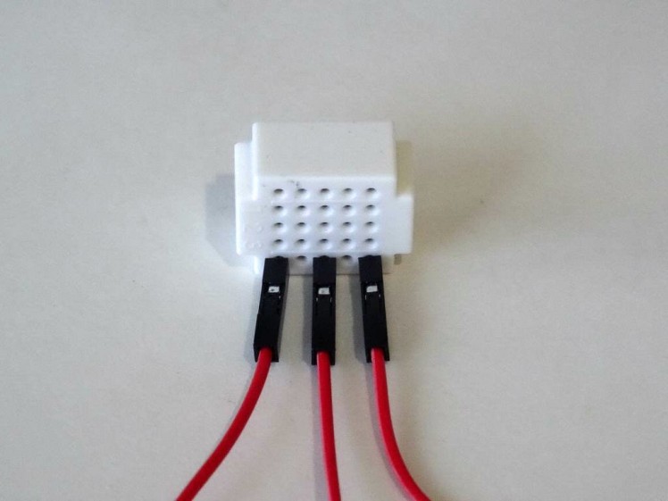
- Connect Female-MalePower(Red wire) to the GPS Module
- Connect Female-Female Ground(Black wire), and TX(Gray wire) to the GPS Module
- Connect the other end of the Ground wire(Black wire) to Ground pin of the Arduino board (Picture 2)
- Connect the other end of the TX (Gray wire) to RX pin of the Arduino board (Picture 2)
- Picture 3 shows in Red where are the Ground, and RX pins of the Arduino Nano (In Blue are shown the connections made in the previous step)
Connect the Male ends of the 3 Power wires(Red wires) - from the Display, the GPS Module, and the Arduino together as example with the help of a Breadboard (Picture) - In my case I used a small Breadboard
Step 12: And play...
1 / 2 • Picture 1

Picture 1

Picture 2
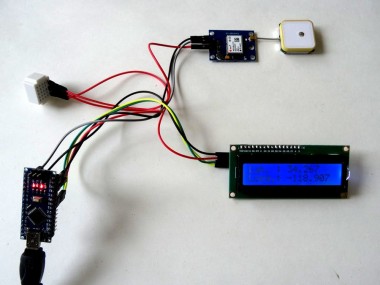
Congratulations! You have completed the project.
Picture 1 shows the connected and powered up project. If you power up the project, after a while the blue LED of the GPS will start blinking about once a second as you can see on the Video. Usually shortly after that, the GPS will start sending location data, and it will be shown on the LCD. Depending on the location, it can take up to few minutes to show the location data. If after a few minutes the data is still not shown, power down the project wait about a minute and power it again to reset the GPS.
On Picture 2 you can see the complete Visuino diagram.Also attached is the Visuino project, that I created for this Tutorial. You can download and open it in Visuino: https://www.visuino.com
Credits
Related products


Leave your feedback...