
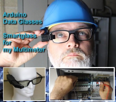
Arduino Glasses A Hmd For Multimeter

Made by Alains Projects / 3D Printing / Augmented Reality / Displays / Virtual Reality / Wearables
About the project
Building an HMD with no special parts, to make work easier and safer
Project info
Difficulty: Difficult
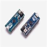
Platforms: Arduino
Estimated time: 4 weeks
License: GNU General Public License, version 3 or later (GPL3+)
Items used in this project
Hardware components

View all
Story
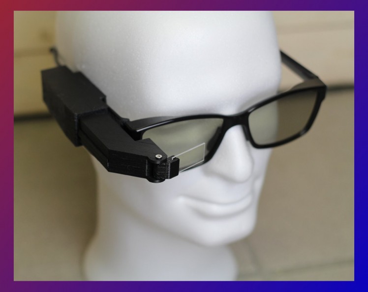
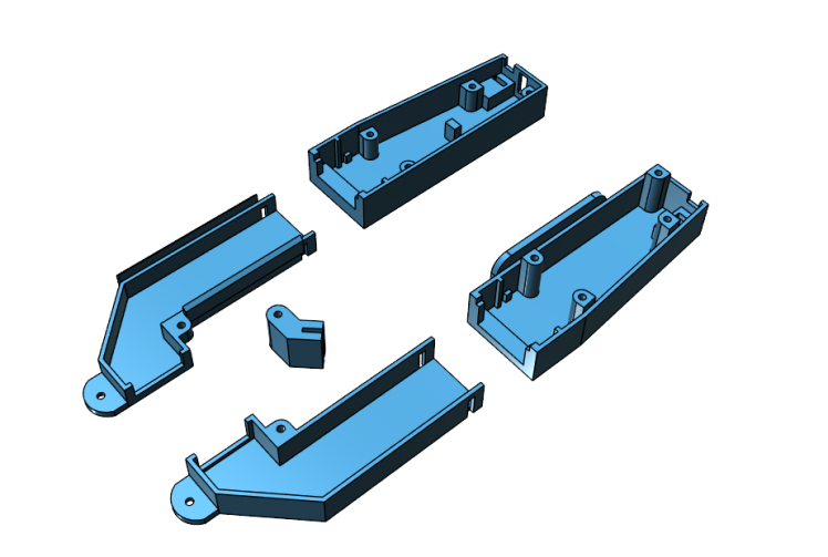
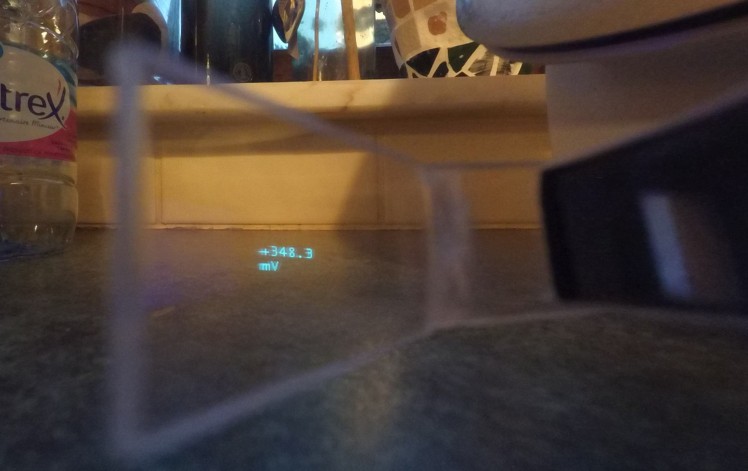
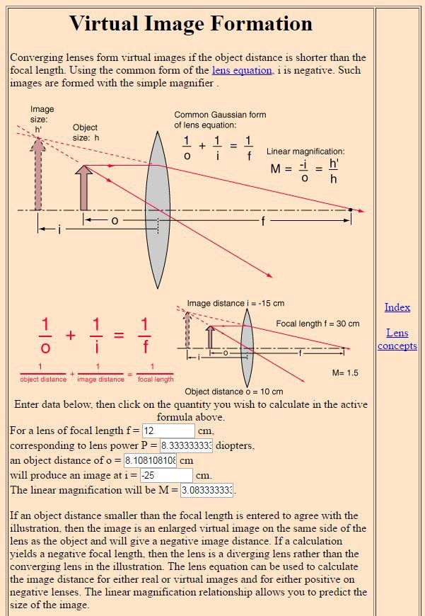
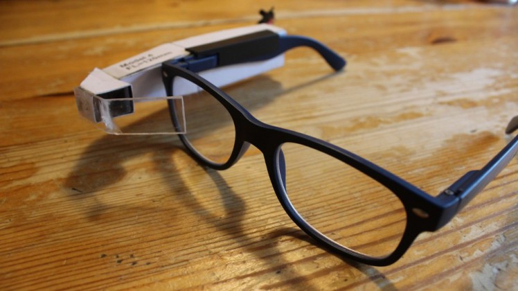
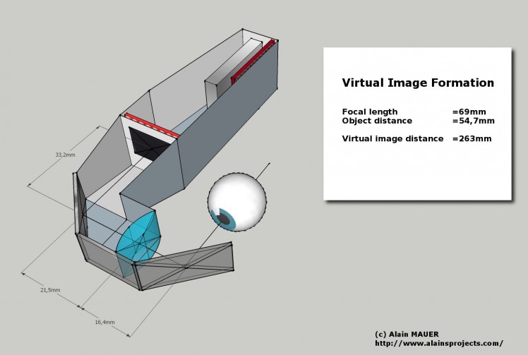
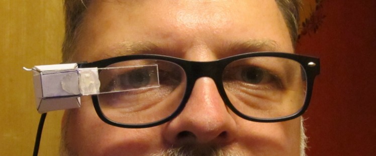
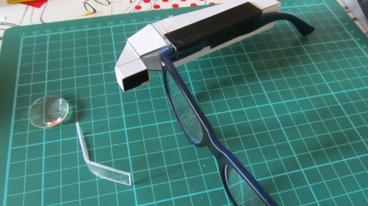
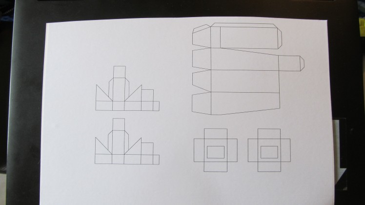
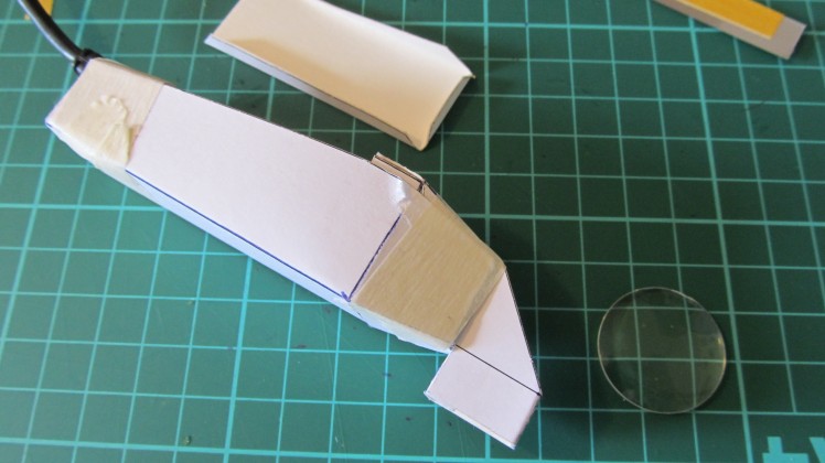
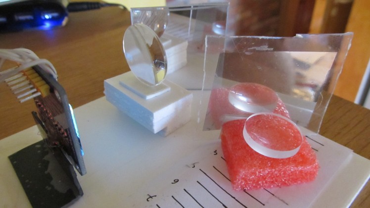
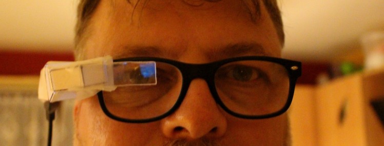
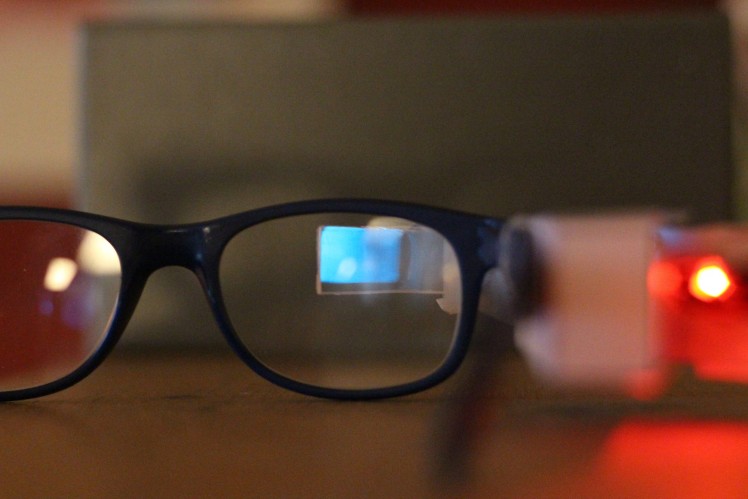
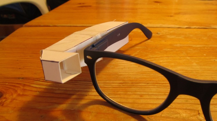
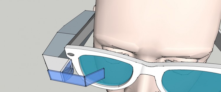
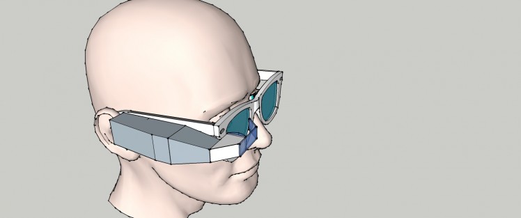
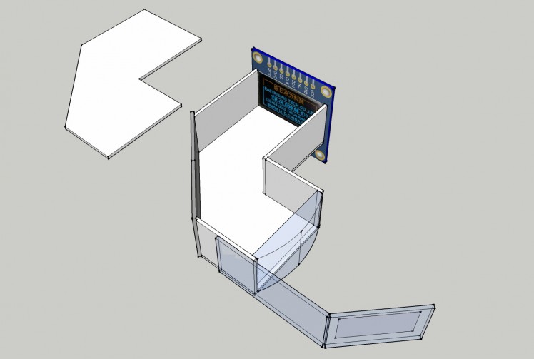
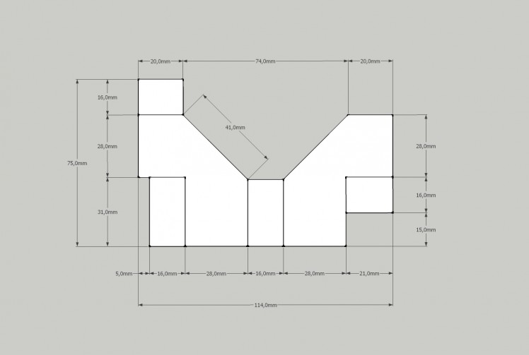
Trying to build a cheap Arduino Data Glasses for everybody.It's working, and now it can even help to avoid accidents. From the first idea to the working prototype, it took 4 MonthThe challenge was, that It should be constructed out of common materials that can be found easily.The project is more about how to build the optical system for this HMDI have a few ideas and one of them is to connect it to a Multimeter over Bluetooth to get the Data right in front of my eyes.One thing is clear, you can not just place a screen in front of your eyes, because it will not be possible for them to focus it.In the logs you can see from the first tests to what I have now. The whole project runs under Open Source License.And please, if you use my design, do not forget to mention that it is based on my idea and add a link to my homepage www.alainsprojects.com.Thank y The optical design will be the most difficult part, but I think I found a solution for this. Follow the project logs to see the updates. The costs of the prototype amounted to 70Euros. Video of the working device Link to the video and Link to the video in German One of the Prototypes The lens was a tricky thing. I had not really an Idea about optics. So I googled and googeld, and I learned a lot about real images, virtual images focal points, and magnification. The best working lens is an Acrylic Plano convex lens with a focal point of 100mm. If you place the screen at a distance of 73mm from the lens away, you will get a virtual image at a distance between 27-30cm. The magnification factor is x3 That's perfect, because another important thing is, that your eyes can only start focusing things at +-25 cm I found this website to calculate the object distance.http://hyperphysics.phy-astr.gsu.edu/hbase/geoopt/image4.html Here are all the parts for the >very well For the final version, I used my 3D printer. The style file has been created in 123design. I need to make a few modifications to the design, but it's not bad for the first try.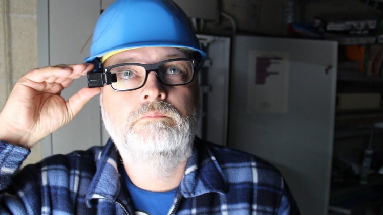

Details
Instructions
Step 1
How it works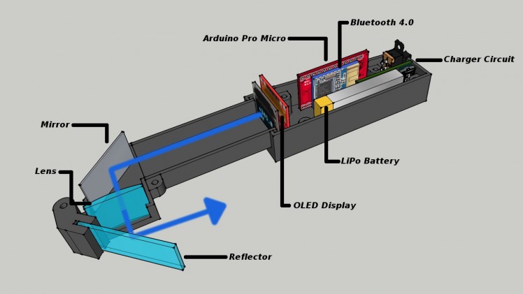
Step 2
The Lens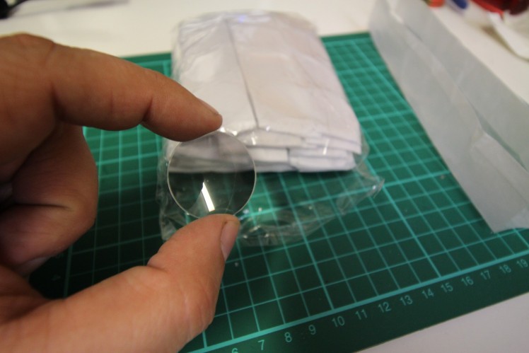
Step 3
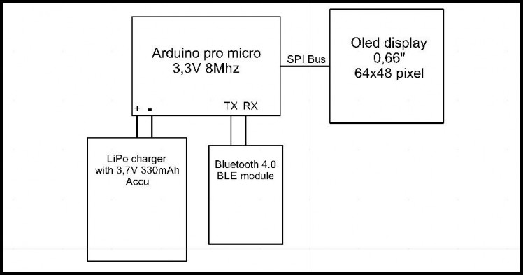
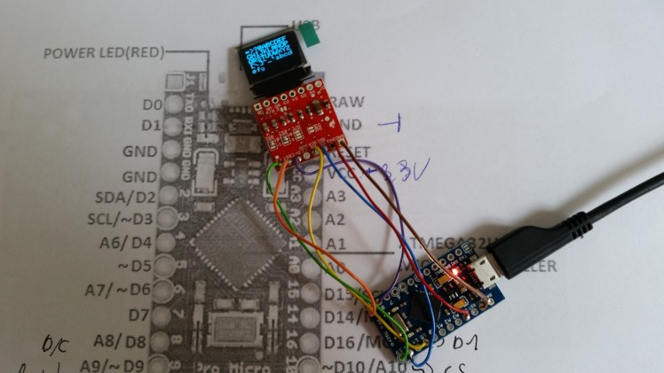
The electronic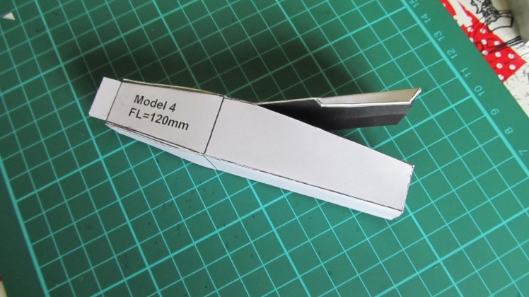
Step 5
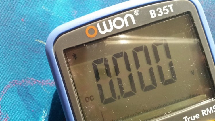
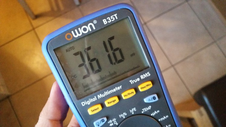
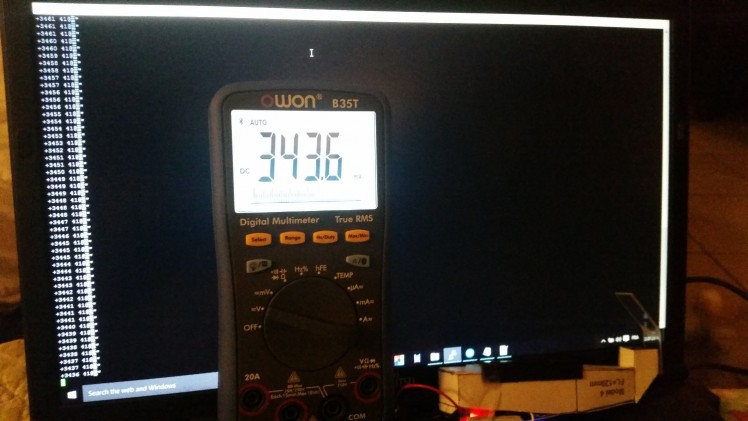
Connecting the Owon B35T Multimeter
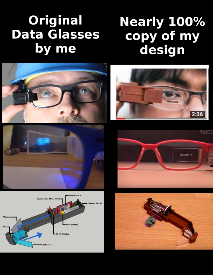
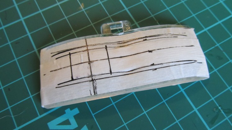
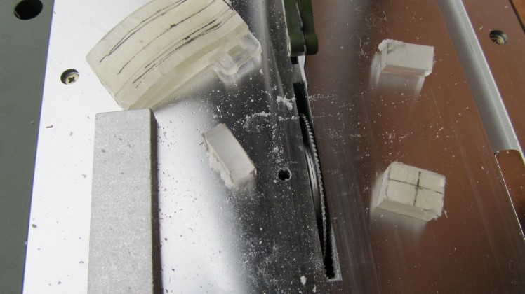
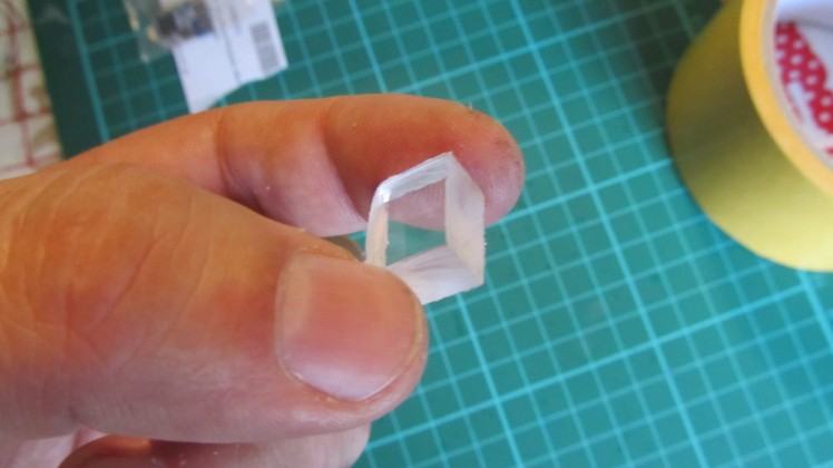
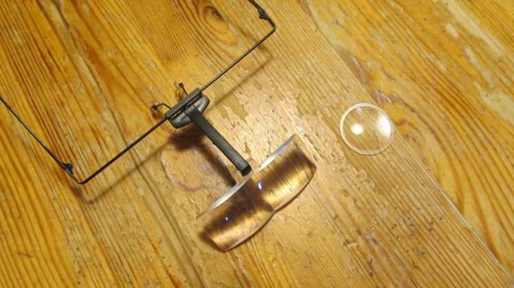
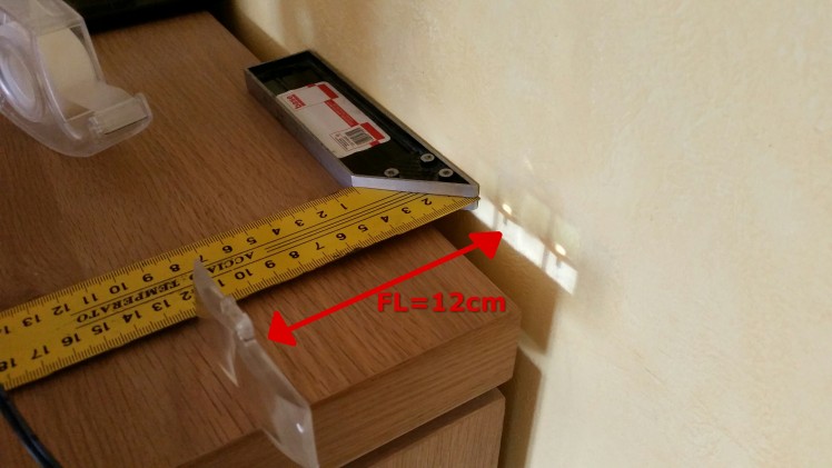
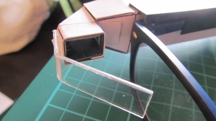
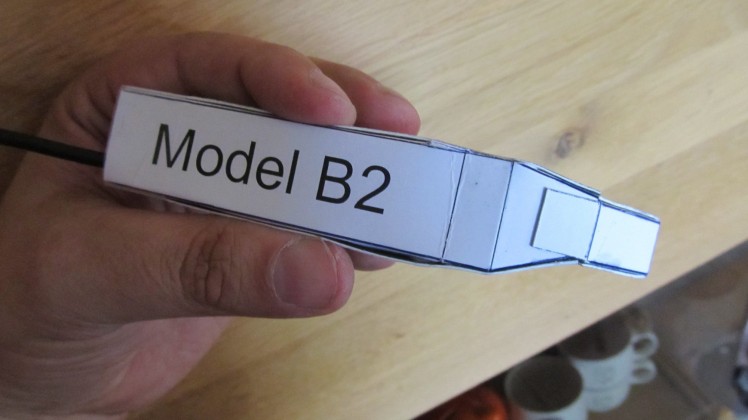
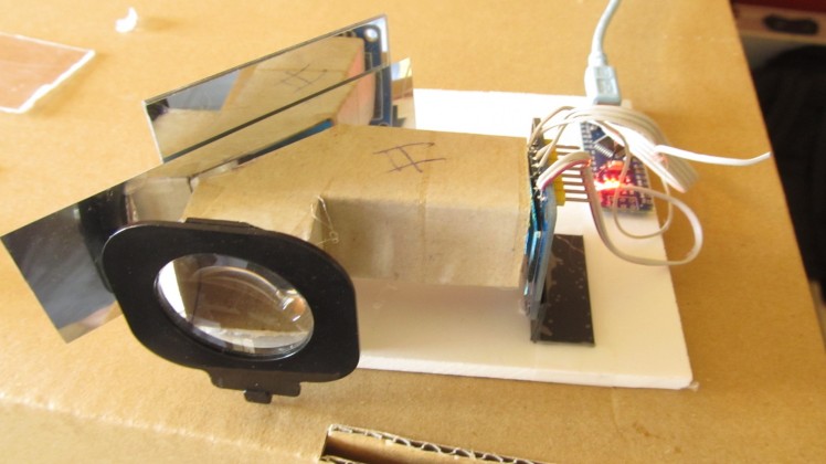
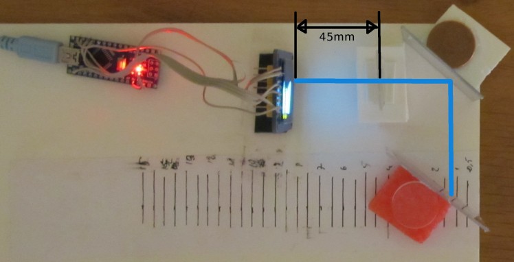
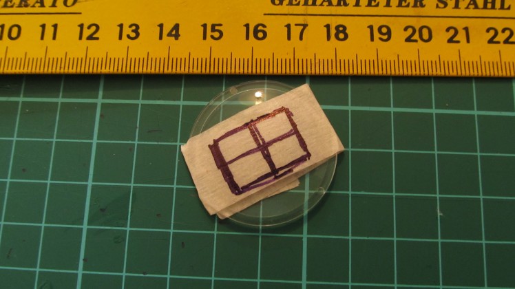
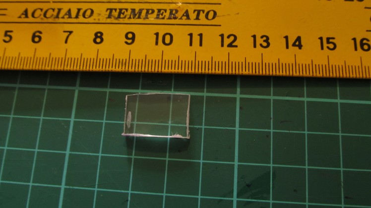
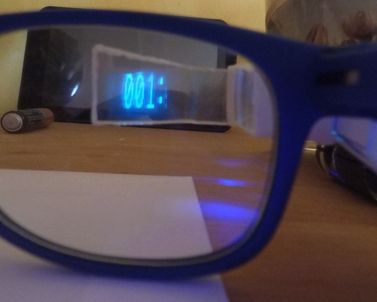
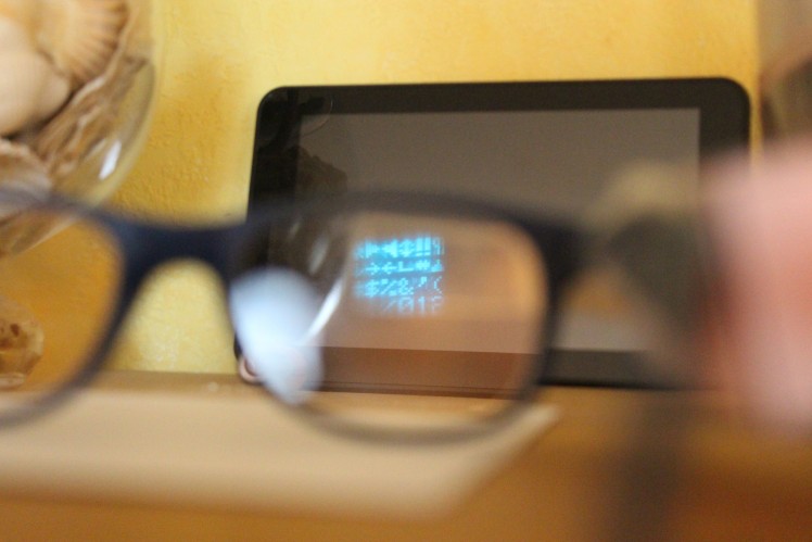
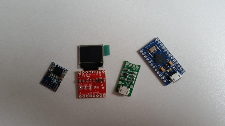
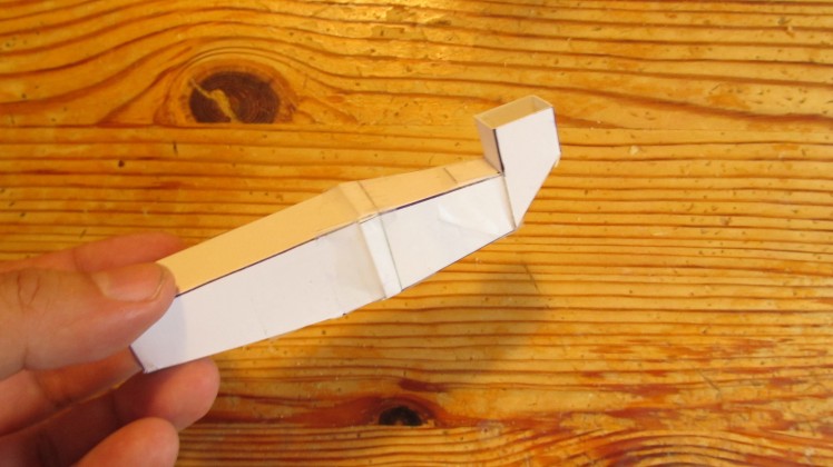
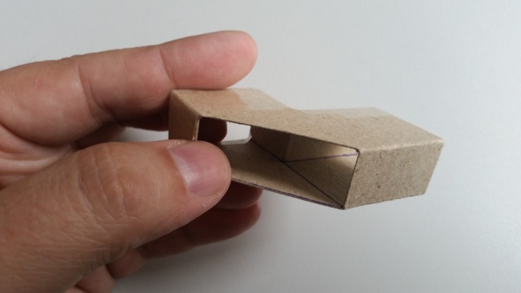
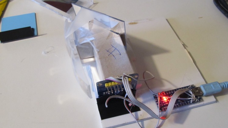
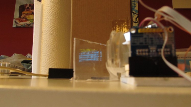
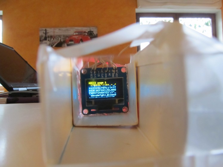
Thes software can be found at my github https://github.com/awall9999/Arduino-Glass I'm really feeling pissed off, when I see people using my designs and try to sell them as their idea. This guy makes a nearly 100% copy of my Data Glass and only after I send him an email he added "inspired by Alain^s Projects". just inspired, really ??????? I think that's not the way open source should work. If you use the work of someone else, the minimum is to mention this person and set his website link in the description. The only thing which calms me down, is that it is still my invention and other people will know it. Hi, the lens is still the problem, because it is not easy to find. I think, I found a good alternative. A small Fresnel lens. Easy to find, cheap and you can cut it with a pair of scissors. Hopefully I will find the time to test it. The focal length is about 110mm, with should be fine. The new displays just arrived. Will build a smaller version. I think I will start a new project for this. Thinks to do: Finally, all fits together.Now a nice video of it, a full description and I'm done. I needed to change the LiPo batteries. I use now a smaller, 280mA, instead of the 330mA. For this I had to change the resistor in the charger circuit. It's 3k smd part. I soldered a normal resistor with the value of 5.6k in place to reduce the charging current to 200mA. Until now, I heated the reflection screen and bent it to 45 degrees. To make the construction easier I printed a new holder. In the picture, you can see the difference I finally start handling the 123Design software and my 3d Printer.I was totally focused on my cardboard design enclosure, but at the end, I had to redesign the glasses due 3d print problems. Now you can adjust the reflection screen, to get the best view.In the next few days I'll test the electronic with the new LiPo, but I'm still waiting for the lenses. I finally printed out the covers for the enclosure. The mirror and the lens are mounted with all the electronics. All fits in, and it works great. This one has a lens with a focal point of 100mm. All in. The controller, bluetooth, display, charger and the LiPo Batterie. I just bought me a 3d Printer, and this is the first enclosure for my Dataglasses. I finaly can recieve all the width="500" height="281" src="//www.youtube.com/embed/GyuO3rePoHM" frameborder="0" allowfullscreen=""> This Weekend I designed a new body for my glasses and I finally ordered a 3d Printer.Now I have to adapt this Sketchup in 123D Design I can now charge the Glasses over the charging board, or transferring >USB ports. I decided to add a Micro USB breakout board to have just one part, where I can program the Arduino, and in same time charge the Arduino Glass. It took me a few days to analyse the Data coming from my Bluetooth Multimeter Owon B35T. After I understood most of the values, I wrote a little program to transfer the Data directly to my Arduino Glass. Amazing, connecting to measuring points, and seeing the Data directly in front of where you are working. I've worked a little bit on the software. I configured the Hm11 as central and I let the module search for BT4.0 devices. After a few try's I made it work. I used a simple written Arduino program to send the serial, Bluetooth >USB and vice versa. Now I receive the id="38e5c4acfafa58219397df3531ce8f8b-a1a794bef71871a0fb98a944dca6a4a264bd4fb6" title="serialtest3.ino">serialtest3.ino) void setup() { Serial.begin(9600); // opens serial port, sets target="_blank">http://hyperphysics.phy-astr.gsu.edu/hbase/geoopt/image4.htmlThe best optics for this project are lenses with a focal length between 100mm and 120mm.The Maginifiging effect will be between 2.9x and 3.5x, witch gave the best results and the distance between the lens and the display will be something between 70mm and 80mm. Yesterday I wrote a little program to test the Data transmission to the Arduino glasses.On the mobile with min. Android 4.3 I use now this terminal software: HM BLE Terminal.I made this quick video to demonstrate. Link to the video Ok, I found the time to connect the Bluetooth 4.0 module. Looks good, and the current for the whole thing is about 24mA. Will take more when I start to transmitt >schematic of my prototype. The only thing that is not implemented yet is the Bluetooth module (maybe this weekend) Here is the build of my Prototype 4. This one has a lens with a FL of 120mm and a LiPo Accu. It's build again out of cardboard. The bluetooth modul will be added soon My lipo finally arrived. And charging ... The main challenge was to build it with easy to find parts, but the lens is a problem. I had a pair of perfect lenses (the lens on the right. A plan convex lens with a size of 33mm and a FL of 100mm), but these are difficult to find. In China I had the possibility to buy them by 100 pieces min. order.So I took the weekend for a few optical tests and the winner is.... the lens of my magnifying head glasses. There are 3 lenses in the set, but the one we need is the big one with a magnifying of 3,5. The frame of these head magnifier will be used to hold the >of the whole thing is about 10$. It has a focal length of 12cm so that the way from the screen to the lens will be 8,1 cm, with a magnifying factor of 3,. On picture 2 you can see how I found the focal length. I made the >trial an error challenge. So I took a google crash course in optics. First of all I had to understand the difference between a real and a virtual image with lenses. Then a very important thing is, that a human eye can only focus an object with a distance of min 25cm. And all what I needed was this formula (1/f) = (1/s2) + (1/s1) where f is focal length of the lens s1 is object distance to the lens and s2 is the distance of the virtual image. I will build now Version III based on this calculation. Today the result of my lenses tests. All the easy to find lenses does not give the result I want.The only one which works is the one from the video, the lens from a cheap Chinese 3d viewer.Problem is, that I have no technical >choice, so I will try a few other lensesHere now the B2 version with lens and screen mounted. Works but I'm still not satisfied Version II of my Arduino Glasses. Again build out of cardboard. Goes much faster than a 3d Printer (if I had one)I added a sort of clip to attach it to the glasses. Hopefully I will add the lens and the screen this evening. Now it's sure, the Google cardboard lens has a shorter focal point. So I had to redesign my prototype and it seems to work. Need to cut the lens. It seems that the lens I used is not the same as the lenses in a google cardboard. This is not what I wanted, I want to build this item that everybody can rebuild it. I used for my first prototype, witch works, a lens from these cheap 3d glasses. And this was the testsetup. And now I has to redo the tests with original google cardboard lenses. There is still a little ghost picture in the screen, so that I try another optic system. Looks better for the moment, but I have to change the lens -> screen setup. I searched and found a lens with f=45mm, and I trimmed it to the correct size. I could not resist to test it instantly, and the result is stunning. I tried to photograph it, so that you can imagine the result. Yes, it works. It is still the wrong lens with a focus point of 68. The correct one should arrive end of this week.But it works. the Plexiglas in front of my eye is nearly invisible, but I can see and read the display.It´s even working better than I thought. Now I´m realy motivated to finish this project To capture the working device on photo, will take me much more efforts :) Yes, the display works. I installed the display demo on it. Next step, hopefully this evening, is the focus test. My electronic components are there. Just the Lipo is still missing First test with a cardboard housing and a 0.96 inch oled display. Memo to myself: I NEED A F****ING 3D Printer This time with a Mirror Looks good, but I used a plastic mirror and I got a ghost image due the dual reflection. Working on a better solution... In the first test setup, I used an oled display an adruino nano and a lens from my magnifying glass headband. Focus point is in about 10cm and displayed on a cd case.Step 6
The Arduino Data Glasses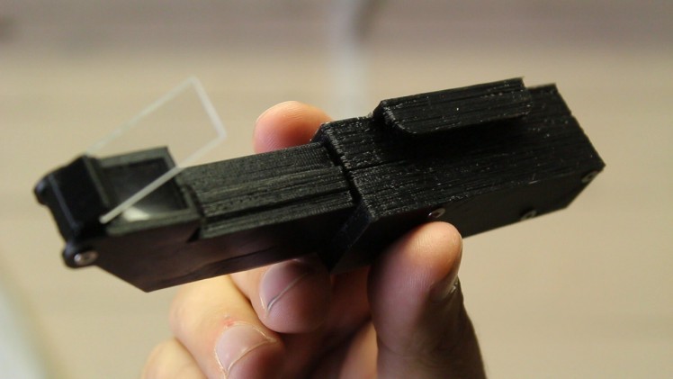

Project Logs
Feeling pissed off
Lens Alternative

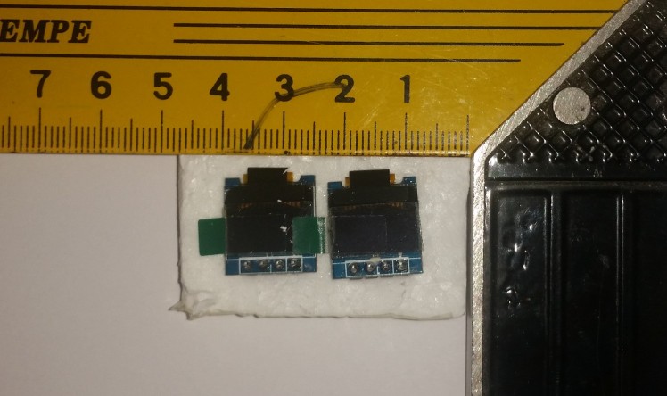
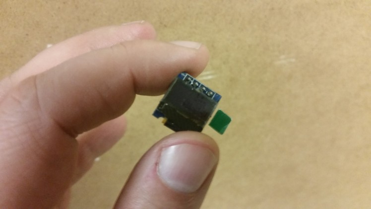
New Display 0.49 inch
Things to do
The end is near

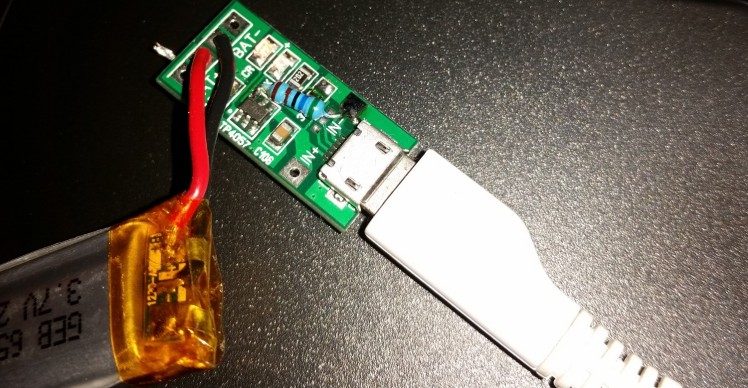
Modifying the charger circuit
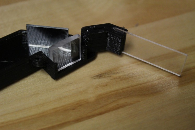
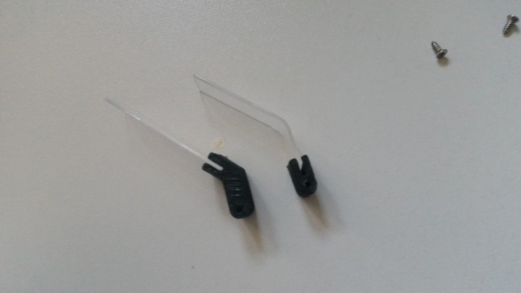
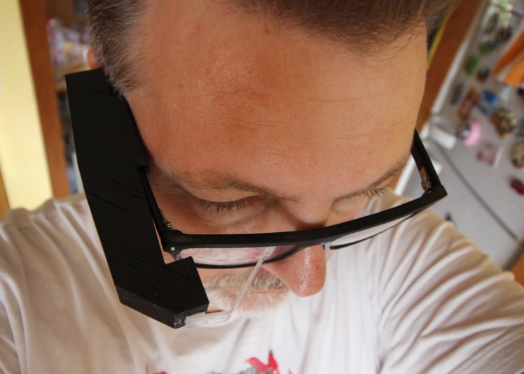
A small reflector modification
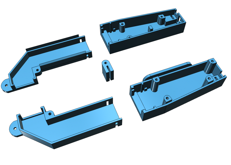
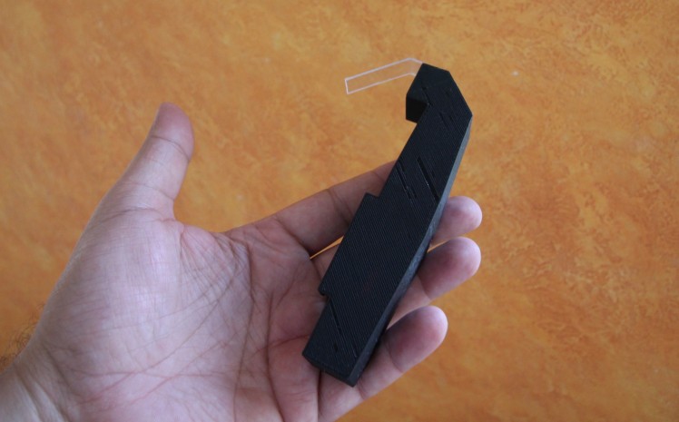
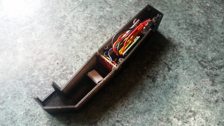
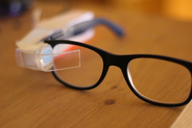
I looks like this will be the final design
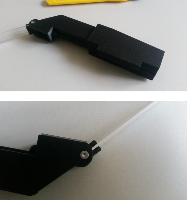
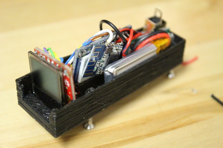
B.T. Data Glasses in his new enclosure
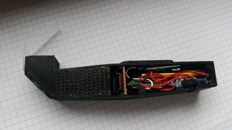
First 3d printed enclosure
Quick Update on the software
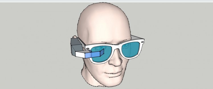
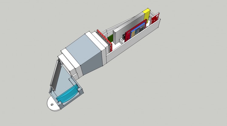
New Body Design for 3D Print
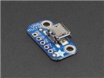
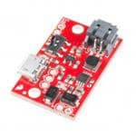
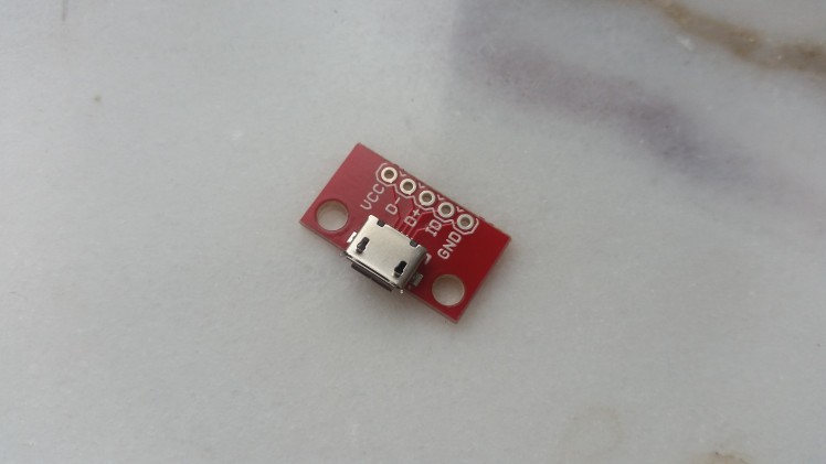
Adding a Micro Usb port
Multimeter connected to my Glasses
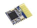
Bluetooth Central
Bluetooth transmission test
Bluetooth connected

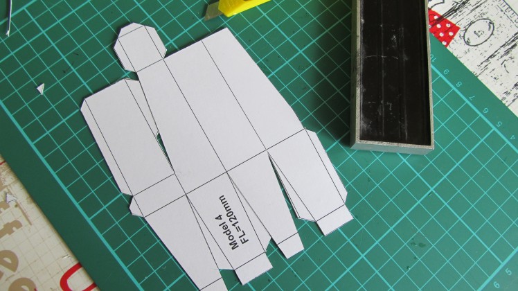
Prototype IV

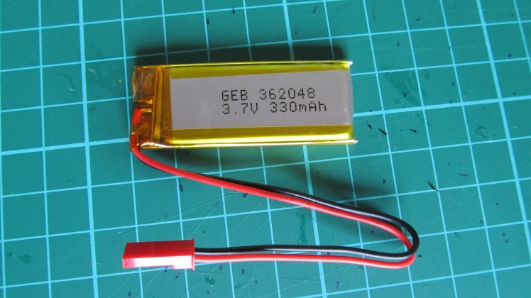
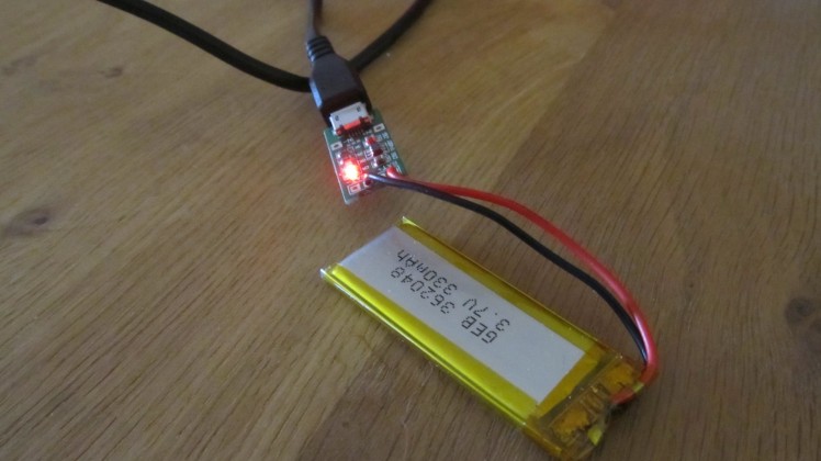
Lipo 3.7V
I found the "easy to find Lens"
Lens Calculation
Lens Update
Version B2 with a focal point of 45mm
New Design
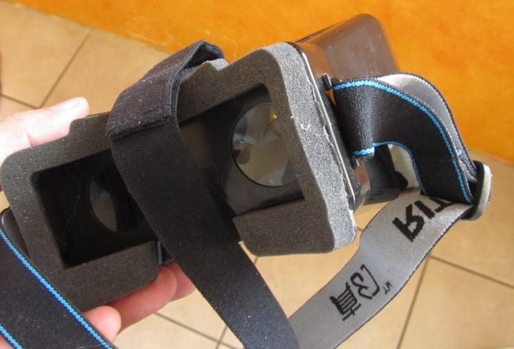
Lens differences
Testing an other optic version
Stunning Results

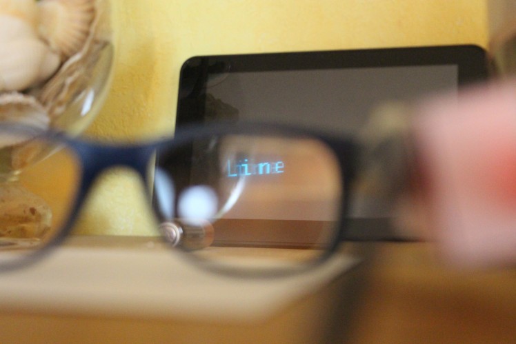
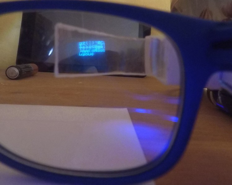
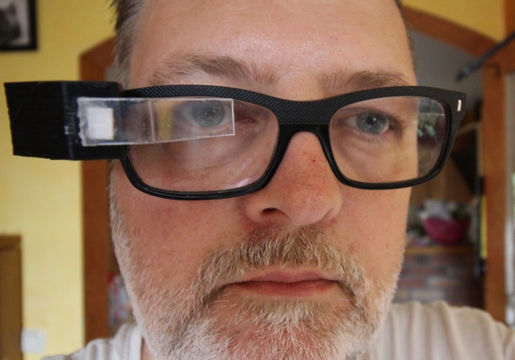
First real test
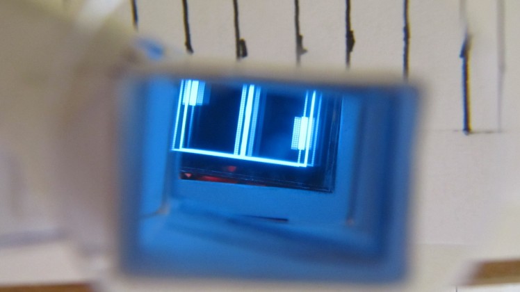
Oled Display Test
The parts are there
Design Test
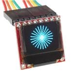
Construction with 0.96 Oled Display
Second Test Setup
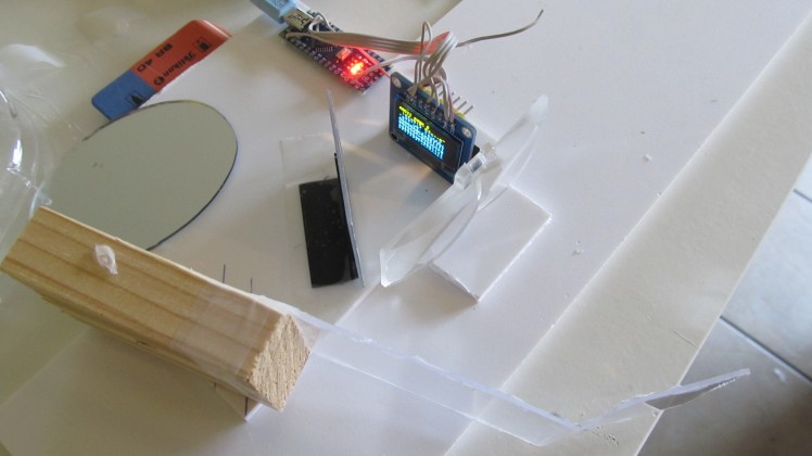
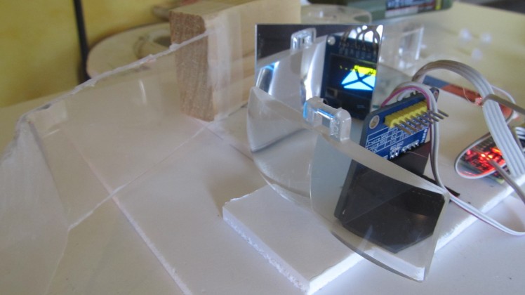
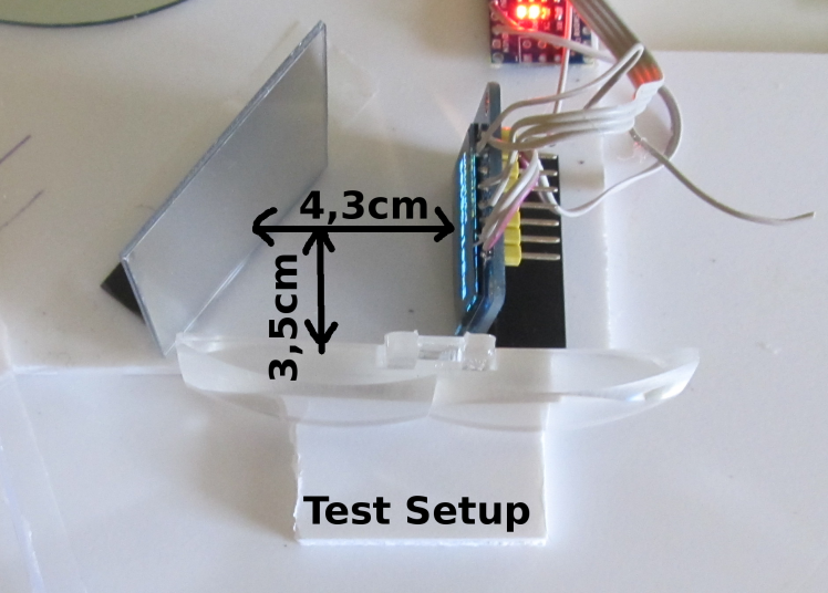
First Test Setup

Code
Credits
Related products


Leave your feedback...