

Arduino Dds Frequency Sweep - Signal Generator Ad9850

About the project
In this tutorial we will learn how to make a Pulse Generator with a Frequency Sweep using DDS Frequency Signal Generator AD9850.
Project info
Difficulty: Moderate
Platforms: Arduino, Visuino, Analog Devices
Estimated time: 1 hour
License: GNU General Public License, version 3 or later (GPL3+)
Items used in this project
Hardware components

Story
Pulse generator will start with 1Hz and increase its frequency for 0.5Hz every second. Once it reaches 10Hz it wil stop increasing the frequency.
You can set your own Starting frequency, End frequency, Frequency increment, and the increment interval.
The output will be Square waves or Sine Waves.
Watch the Video!
Step 1: What You Will Need1 / 6
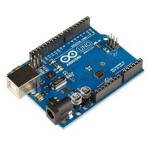

- Arduino Uno or any other Arduino board
- AD9850 (DDS Synthesizer) More Info
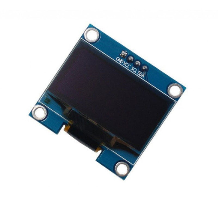
- OLED Display
- Jumper wires
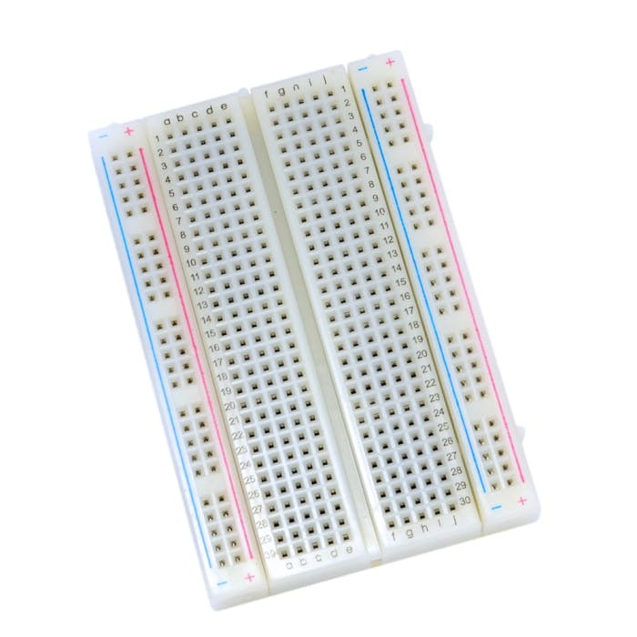
- Breadboard
- Visuino software: Download here
- Oscilloscope (Optional)
1 / 2


Thank you PCBWay for supporting this tutorial and helping users learn more about electronics.
NEW! Now you can get Aluminum PCB & FLEX PCB in their Special Offer!
What I like about the PCBWay is that you can get 10 boards for approximately $5 which is really cost effective for professional made boards, not to mention how much time you save!
Go check them out here. They also offer a lot of other stuff in case you might need it like assembly,3D printing,CNC machining and a lot more.
Step 3: Output Response1 / 2
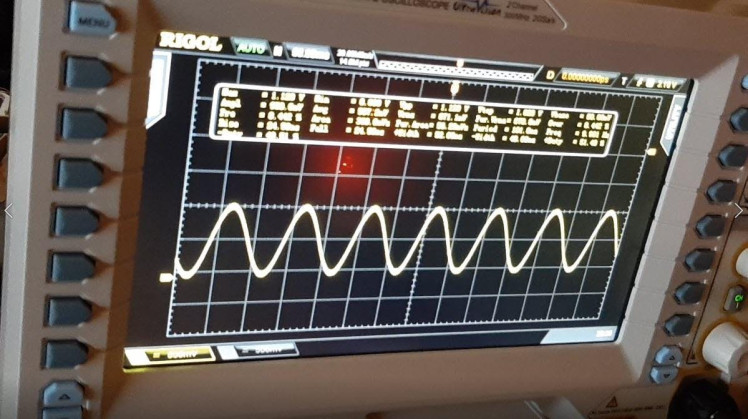
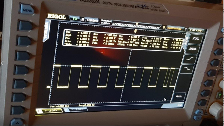
You can see the output results for the frequency 10Hz
- First picture is Scope connected to SQ Wave 1 pin
- First picture is Scope connected to Sine Wave 1 pin
1 / 2
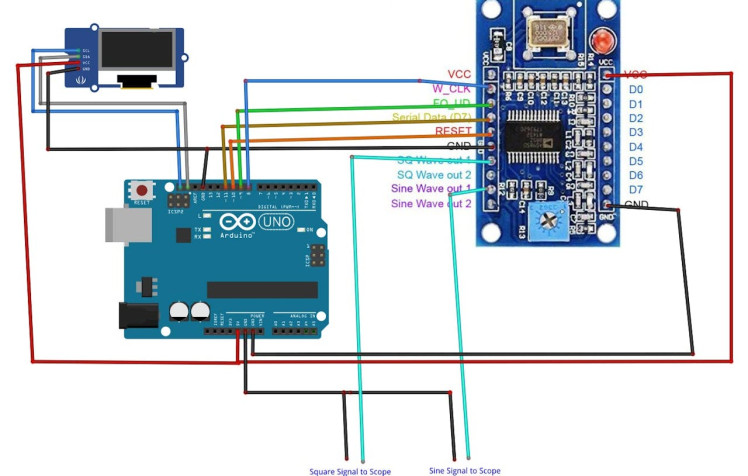
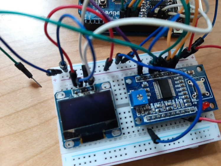
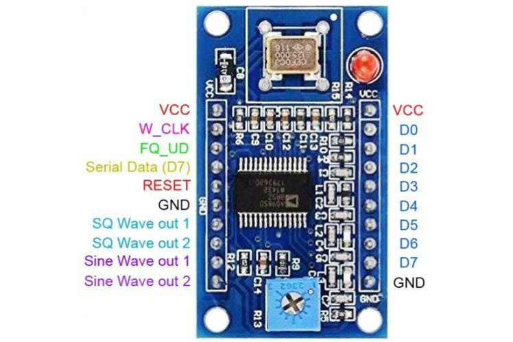
- Connect "AD9850" module pin Serial "W_CLK" to Arduino Digital pin 8
- Connect "AD9850" module pin Serial "FQ_UD" to Arduino Digital pin 9
- Connect "AD9850" module pin Serial "Serial Data" to Arduino Digital pin 11
- Connect "AD9850" module pin Serial "Reset" to Arduino Digital pin 10
- Connect "AD9850" module pin VCC to Arduino pin 5V
- Connect "AD9850" module pin GND (On both sides) to Arduino pin GND
- Connect OLED Display pin [SCL] to Arduino pin [SCL]
- Connect OLED Display pin [SDA] to Arduino pin [SDA]
- Connect OLED Display pin [VCC] to Arduino pin [5v]
- Connect OLED Display pin [GND] to Arduino pin [GND]
1 / 2
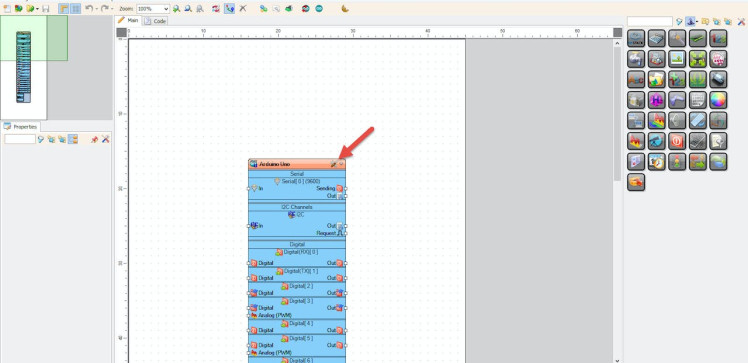
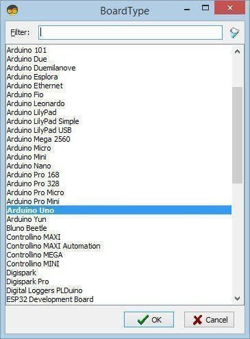
Start Visuino as shown in the first picture Click on the "Tools" button on the Arduino component (Picture 1) in Visuino When the dialog appears, select "Arduino UNO" as shown on Picture 2
Step 6: In Visuino Add Components1 / 10
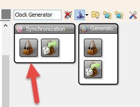
- Add "Clock Generator" component
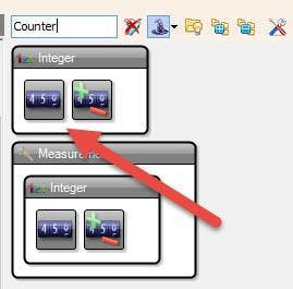
- Add "Counter" component
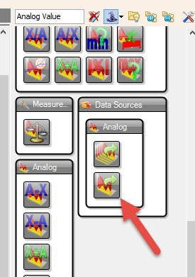
- Add "Analog Value" component
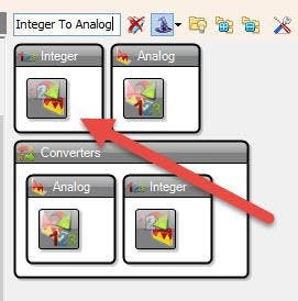
- Add "Integer To Analog" component
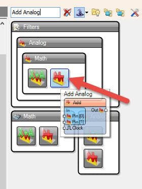
- Add "Add Analog" component
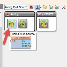
- Add "Analog Multi Source" component
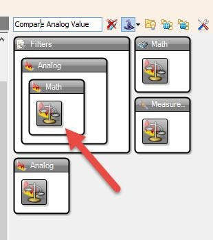
- Add "Compare Analog Value" component
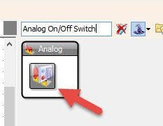
- Add "Analog On/Off Switch" component
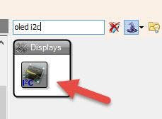
- Add "OLED I2C" component
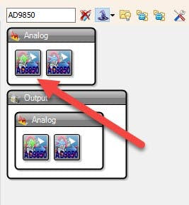
- Add "Analog Devices Serial DDS Synthesizer (Signal Generator) - AD9850" component
1 / 8
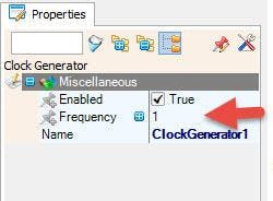
- Set the Interval: Select "ClockGenerator1" and in the properties window set frequency, in our case it is 1Hz, this means that the frequency will increase every second
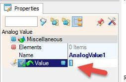
- Set Start Frequency: Select "AnalogValue1" and in the properties window set "Value", in our case it is 1, this means that we will start with the frequency 1Hz
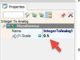
- Set Frequency Increment: Select "IntegerToAnalog1" and in the properties window set "Scale", in our case it is 0.5, this means that the frequency will increase for 0.5Hz every time
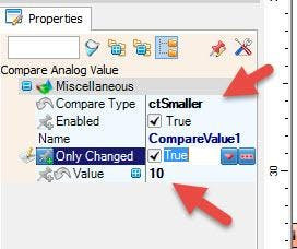
- Set End Frequency: Select "CompareValue1" and in the properties window set "Compare Type" to ctSmaller and "Value", in our case it is 10, this means that the frequency will stop increasing at 10Hz
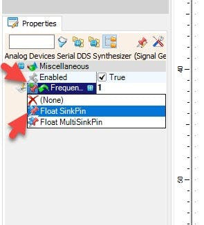
- Select "Synthesizer1" and in the properties window select "Frequency" and click on the Pin Icon and select "Float SinkPin"
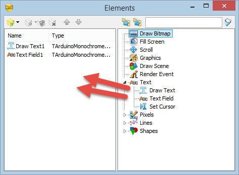
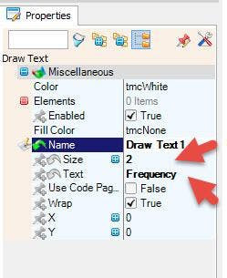
- Double click on the "DisplayOLED1" and in the "Elements" window drag "Draw Text" to the left side and in the Properties window set "Text" to "Frequency" and "Size" to 2
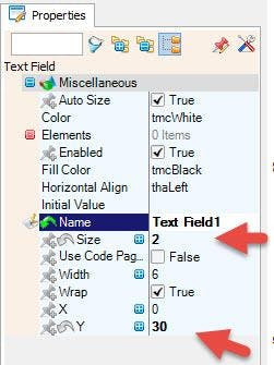
- In the "Elements" window drag "Text Field" to the left side and in the Properties window set "Size" to 2 and "Y" to 30
- Close the "Elements" window
1 / 2
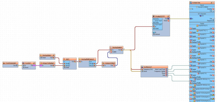
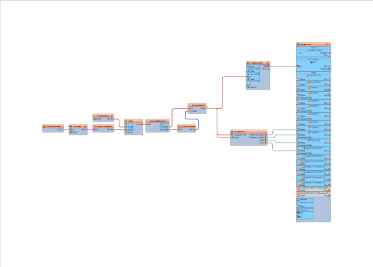
- Connect "ClockGenerator1" pin [Out] to "Counter1" pin[In]
- Connect "Counter1" pin [Out] to "IntegerToAnalog1" pin[In]
- Connect "AnalogValue1" pin [Out] to "Add1" pin[0]
- Connect "IntegerToAnalog1" pin [Out] to "Add1" pin[1]
- Connect "Add1" pin [Out] to "AnalogMultiSource1" pin[In]
- Connect "AnalogMultiSource1" pin [0] to "AnalogSwitch1" pin[In]
- Connect "AnalogMultiSource1" pin [1] to "CompareValue1" pin[In]
- Connect "CompareValue1" pin [Out] to "AnalogSwitch1" pin[Enable]
- Connect "AnalogSwitch1" pin [Out] to "Synthesizer1" pin[Reset]
- Connect "AnalogSwitch1" pin [Out] to "Synthesizer1" pin[Frequency]
- Connect "AnalogSwitch1" pin [Out] to "DisplayOLED1" > "Text Field1" pin[In]
- Connect "DisplayOLED1" pin [I2C] to Arduino pin[I2C]
- Select "Synthesizer1" component and connect pin "Word Load Clock" to Arduino digital pin 8
- Select "Synthesizer1" component and connect pin "Frequency Update" to Arduino digital pin 9
- Select "Synthesizer1" component and connect pin "Reset" to Arduino digital pin 10
- Select "Synthesizer1" component and connect pin "Data" to Arduino digital pin 11
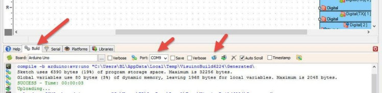
In Visuino, at the bottom click on the "Build" Tab, make sure the correct port is selected, then click on the "Compile/Build and Upload" button.
Step 10: PlayIf you power the Arduino module, The OLED Display will show the increasing Frequency. If you have an Oscilloscope you can connect it to the AD9850 SQ Wave 1 pin (see wiring schematic) or AD9850 Sine Wave 1 pin (see wiring schematic).
Congratulations! You have completed your project with Visuino. Also attached is the Visuino project, that I created for this tutorial, you can download it and open it in Visuino: https://www.visuino.eu
Schematics, diagrams and documents
Code
Credits
Related products


Leave your feedback...