
Arduino: Connect 4d Systems Visi Genie Smart Display

About the project
Connect 4D Systems ViSi Genie smart Touch Screen Display to Arduino, and program it - Quick and Easy!
Project info
Difficulty: Moderate
Platforms: 4D Systems, Arduino, Visuino
Estimated time: 1 hour
License: GNU General Public License, version 3 or later (GPL3+)
Items used in this project
Hardware components

Software apps and online services
Story
There comes a time, when you want to have a touchscreen display connected to your Arduino board. There are many different Display options and sizes available, but most of them require considerable amount of code to be controlled, and it is not easy to create cool looking user interface.
4D Systems has found a great solution for the problem. They have designed advanced, smart programmable displays that have their own controller, serial interface, and even built-in GPIO. The folks at 4D Systems have also created an easy to use graphical development environment called 4D Systems Workshop that allows you to design the user interface and program the Displays.
Last year the folks at 4D Systems were nice enough to donate couple of displays and I added support for them in Visuino, making it very easy not only to design the User Interface for the display, but also to program the Arduino to work with the user interface.
In this Tutorial, I will show you how easy it is to add touchscreen user interface to your Arduino board, display data from sensors in cool gauges, and control Servo and Relay with the touchscreen Display.
Step 1: Components
1 / 3 • Picture 1

Picture 1

Picture 2

Picture 3
- One Arduino board. It is better to use a board with more than one Serial ports - in my case Arduino Mega 2560
- One 4D SystemsSmart Touchscreen Display with connector cable ( I used uLCD-70DT/7.0" DIABLO16 Intelligent Display but most others will also work )
- One DHT11 Sensor Module I got from this cheap 37 sensors set
- One Relay Module I got from this cheap 37 sensors set
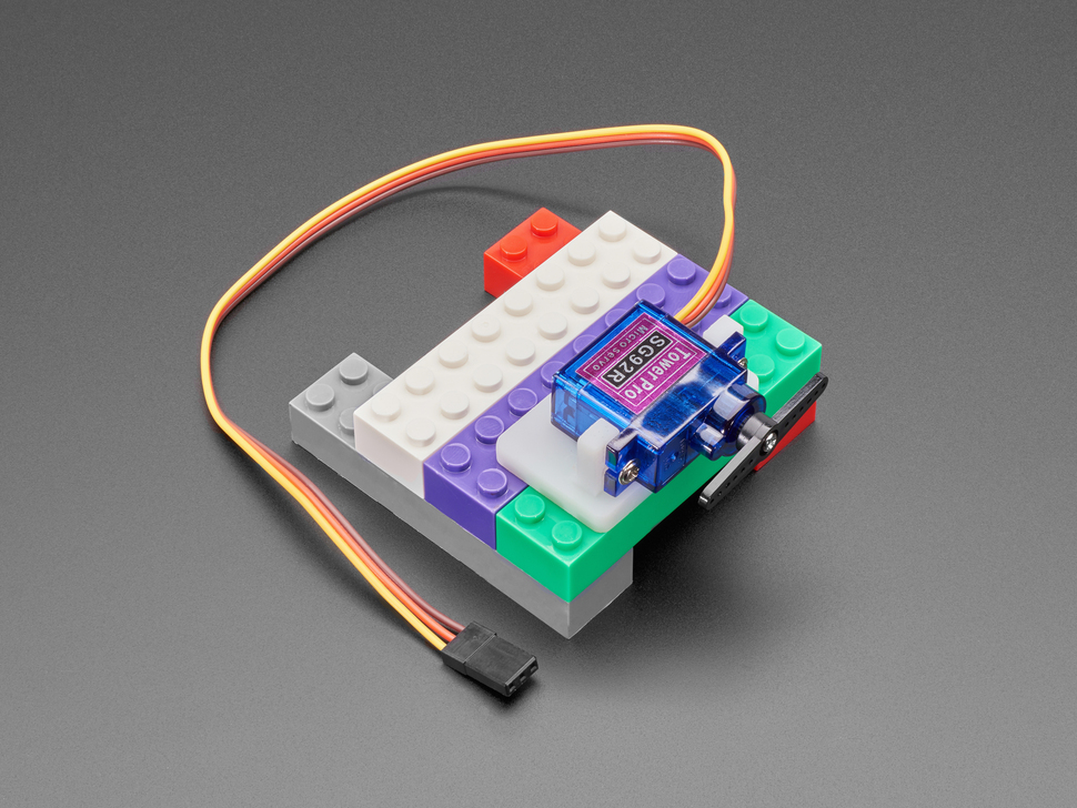
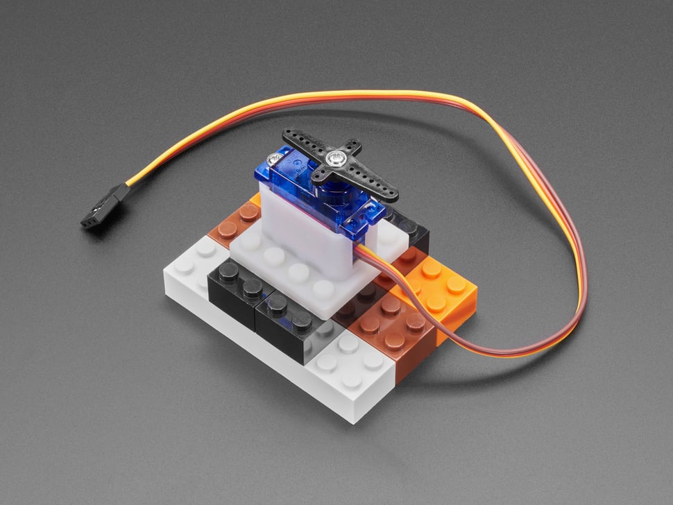
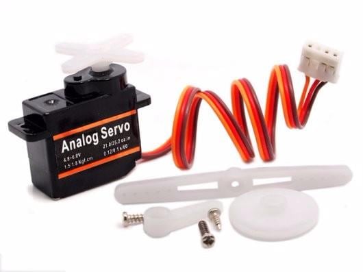
- One Small Servo
- 6 Female-Male jumper wires
- 5 Male-Male jumper wires
- One small Breadboard (Any breadboard can be used)
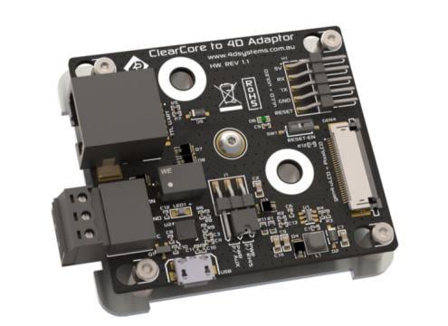
- Optionally: One 4D Arduino Adaptor Shield (rev 2.0) - you can also connect the Display directly with wires, however the shield makes connecting the display to Arduino easier
- To program the 4D Systems display, you will need a uUSB-PA5 programming adapter (Picture 2)
- If your computer does not have a slot for connecting MicroSD cards, you will also need a MicroSD USB adapter (Picture 3)
1 / 7 • Picture 1

Picture 1

Picture 2

Picture 3

Picture 4

Picture 5

Picture 6

Picture 7
- Remove the Configuration Jumpers from one of the 4D Display channels of the 4D Arduino Adaptor Shield (The top channel on Pictures 1 and 2)
- Plug the 4D Arduino Adaptor Shield on top of the Arduino board (Picture 3)
- Connect with a Female-Male jumper wire (Brown wire) the RX pin (Picture 4) of the channel of the 4D Arduino Adaptor Shield to the RX1 pin of the Arduino Mega board (Picture 5 and 6)
- Connect with a Female-Male jumper wire (Orange wire) the TX pin (Picture 4) of the channel of the 4D Arduino Adaptor Shield to the TX1 pin of the Arduino Mega board (Picture 5 and 6)
- Picture 7 shows where the RX and TX pins are on the Arduino Mega and the 4D Arduino Adaptor Shield
1 / 6 • Picture 1

Picture 1

Picture 2

Picture 3

Picture 4

Picture 5

Picture 6
- Connect the Female ends of Female-Male jumper wires to Power(Red wire), Ground(Black wire), and Data(Gray wire) of the DHT11 Module (Picture 1 shows 2 different types of DHT11 sensor modules. As you can see the pins may differ, so connect carefully!)
- Connect the Female ends of Female-Male jumper wires to Power(Red wire), Ground(Black wire), and Relay Control(Blue wire) of the Relay Module (Picture 2)
- Connect Male-Male jumper wires to Power(Red wire), Ground(Black wire), and Servo Control(Yellow wire) of the Servo Module (Picture 3 and 4)
- Connect the other end of the DHT11 Data wire(Gray wire) to Digital pin 2 of the Arduino board (Picture 5)
- Connect the other end of the Relay Control wire(Blue wire) to Digital pin 3 of the Arduino board (Picture 5)
- Connect the other end of the Servo Control wire(Yellow wire) to Digital pin 5 of the Arduino board (Picture 5)
- Picture 6 shows In Red where are the Digital 2, Digital 3, and Digital 5 pins of the Arduino Mega. In Blue are shown the connections done in the previous steps
1 / 3 • Picture 1

Picture 1

Picture 2

Picture 3
- Connect another Male-Male Ground wire(Black wire) to the Groundpin of the Arduino board (Picture 1)
- Connect another Male-Male Power wire(Red wire) to the 5V Power pin of the Arduino board (Picture 1)
- Connect the Other ends of the 4 Power wires(Red wires) - from the DHT11, the Relay Module, the Servo, and the Arduino together as example with the help of a Breadboard (Picture 2) - In my case I used a small Breadboard (To simplify the Tutorial I powered the Servo from the Arduino board. It is recommended however to power it with a dedicated power supply as shown in this Tutorial)
- Connect the Other ends of the 4 Ground wires(Black wires) - from the DHT11, the Relay Module, the Servo, and the Arduino together as example with the help of a Breadboard (Picture 2) - In my case I used a small Breadboard
- Picture 3 shows In Red where are the 5V Power, and Ground pins of the Arduino Mega. In Blue are shown the connections done in the previous steps
1 / 4 • Picture 1

Picture 1

Picture 2

Picture 3

Picture 4
Before you can use the 4D Systems Smart Display, you need to design the user interface, and program it. To program the display, you need to connect it directly to the computer with a uUSB-PA5 programming adapter . You also will need to upload some automatically generated images to the MicroSD card.
- Connect the Display connector cable to the Display matching the labels on the cable connector to the labels on the pins on the board (Picture 1)
- Connect the other end of the connector cable to the uUSB-PA5 programming adapter (Picture 2 and 3)
- If your computer has slot for MicroSD cards, insert the MicroSD card in it, If not use a MicroSD adapter to connect the MicroSD card to the computer (Picture 4)
1 / 2 • Picture 1

Picture 1

Picture 2
If you don't have it already, you will need to install the 4D Systems Workshop. You can download it from here.
- Start the 4D Systems Workshop
- On the left select "New" (Picture 1)
- Select your display type - in my case uLCD-70DT/7.0" Diablo 16 Intelligent LCD Module w/Resistive touch (Picture 1)
- Click on the "Next" button (Picture 1)
- Click on the Arrow button of the ViSi Genie option (Picture 2)
1 / 4 • Picture 1

Picture 1

Picture 2

Picture 3

Picture 4
First we need to add a Gauge and Thermometer to display the data from the DHT11:
- Select the "Gauges" tab on the components toolbar (Picture 1)
- Select the "Cool Gauge" component from the tab (Picture 1) and place it in the display design (Picture 2) - you can resize and arrange the way you want it to appear
- Select the "Thermometer" component from the tab (Picture 2) and place it in the display design (Picture 3) - you can resize and arrange the way you want it to appear
- In the "Object Inspector" on the right, expand the "Scale" property (Picture 4)
- In the "Object Inspector" set the "Min" sub property of the "Scale" to "0" (Picture 4)
- In the "Object Inspector" set the "Max" sub property of the "Scale" to "100" (Picture 4)
- In the "Object Inspector" on the right, expand the "Value" property (Picture 4)
- In the "Object Inspector" set the "Value" sub property of the "Value" to "0" (Picture 4)
1 / 5 • Picture 1

Picture 1

Picture 2

Picture 3

Picture 4

Picture 5
Next we need to add 2 buttons to control the Relay:
- Select the "Buttons" tab on the components toolbar (Picture 1)
- Select the "Button01" component from the tab (Picture 1) and place it in the display design area (Picture 2) - you can resize and arrange the way you want it to appear
- In the "Object Inspector" on the right, click on the "Events" tab (Picture 2)
- In the "Object Inspector" on the right, click on the "..." button next to the value of the "OnChanged" event (Picture 2)
- In the "On event selection" dialog, select "Report message", and click the "OK" button (Picture 3)
- Select again the "Button01" component from the tab (Picture 4) and place it in the display design area (Picture 5) - you can resize and arrange the way you want it to appear
- In the "Object Inspector" on the right, click on the "Events" tab (Picture 5)
- In the "Object Inspector" on the right, click on the "..." button next to the value of the "OnChanged" event (Picture 5)
- In the "On event selection" dialog, select "Report message", and click the "OK" button (Picture 3)
1 / 3 • Picture 1

Picture 1

Picture 2

Picture 3
Finally we need a trackbar to control the Servo:
- Select the "Inputs" tab on the components toolbar (Picture 1)
- Select the "Trackbar" component from the tab (Picture 1) and place it in the display design area (Picture 2) - you can resize and arrange the way you want it to appear
- In the "Object Inspector" on the right, click on the "Events" tab (Picture 2)
- In the "Object Inspector" on the right, click on the "..." button next to the value of the "OnChanged" event (Picture 2)
- In the "On event selection" dialog, select "Report message", and click the "OK" button (Picture 3)
1 / 3 • Picture 1

Picture 1

Picture 2

Picture 3
Once the project is ready, we need to save it and prepare for uploading:
- Select the "Comms" from the Ribbon menu (Picture 1)
- Select the Serial Com port to which the display is connected (Picture 1)
- Select the "Home" from the Ribbon menu (Picture 2)
- Click on the "Save" button (Picture 2)
- In the "Save dialog" save the project (Picture 3)
1 / 5 • Picture 1

Picture 1

Picture 2

Picture 3

Picture 4

Picture 5
Finally we need to build and upload the project to the Display:
- Select the "Home" from the Ribbon menu (Picture 1)
- Click on the "Build Copy/Load" button (Picture 1)
- The Workshop will show the progressing dialog of the files being generated (Picture 2)
- At the end of the processing, the Workshop will offer you to select the MicroSD Flash card where the files will be copied (Pictures 3, and 4)
- After selecting the MicroSD disk, click the "OK" Button (Picture 4)
- Finally, the Workshop will show the copy progress (Picture 5)
1 / 3 • Picture 1

Picture 1

Picture 2

Picture 3
The Display is programmed, and the generated images are uploaded into the MicroSD. Now we need to connect the Display to Arduino and install the MicroSD:
- Unplug the MicroSD card from the computer, and plug it into the MicroSD slot of the Display (Pictures 1 and 2)
- Disconnect the Display cable from the uUSB-PA5 programming adapter
- Connect the Display cable to the 4D Arduino Adaptor Shield (Picture 3)
1 / 2 • Picture 1

Picture 1

Picture 2
To start programming the Arduino, you will need to have the Arduino IDE installed from here: http://www.arduino.cc/.
Please be aware that there are some critical bugs in Arduino IDE 1.6.6.
Make sure that you install 1.6.7 or higher, otherwise this Tutorial will not work!
The Visuino: https://www.visuino.com also needs to be installed.
- Start Visuino as shown in the first picture
- Click on the "Tools" button on the Arduino component (Picture 1) in Visuino
- When the dialog appears, select "Arduino Mega 2560" as shown in Picture 2
1 / 3 • Picture 1

Picture 1

Picture 2

Picture 3
First we need a ViSi Genie 4D Systems Display component to control the Display from the Visono code:
- Type "4d" in the Filter box of the Component Toolbox then select the "ViSi Genie 4D Systems Display" component (Picture 1), and drop it in the design area
- Connect the "Out" output pin of the Display4DSystems1 component to the to the "In" input pin of the "Serial[ 1 ]" channel of the Arduino component (Picture 2)
- Connect the "Reset" output pin of the Display4DSystems1 component to the to the "Digital" input pin of the "Digital[ 4 ]" channel of the Arduino component (Picture 3)
1 / 6 • Picture 1

Picture 1

Picture 2

Picture 3

Picture 4

Picture 5

Picture 6
Next we need to add the elements of the User Interface of the Display so we can work with them in Visuino:
- Click on the "Tools" button of the Display4DSystems1 component (Picture 1)
- In the "Elements" editor select the “4D Button” element, and then click 2 times on the "" button on the left (Picture 2) to add 2 Button elements (Picture 3)
- In the Object Inspector set the "Index" property of the second Button4D Element to "1" (Picture 3)
- In the "Elements" editor select the “Trackbar” element on the right, and then click on the "" button on the left to add Trackbar element (Picture 4)
- In the "Elements" editor select the “Cool Gauge” element on the right, and then click on the "" button on the left to add Cool Gauge element (Picture 5)
- In the "Elements" editor select the “Thermometer” element on the right, and then click on the "" button on the left to add Thermometer element (Picture 6)
- Close the "Elements" editor
1 / 4 • Picture 1

Picture 1

Picture 2

Picture 3

Picture 4
Next we will add a component to get the values from the DHT11, convert them to Unsigned Integers and send them to the Display Gauge, and Thermometer Elements:
- Type "dht" in the Filter box of the Component Toolbox then select the "Humidity and Thermometer DHT11/21/22/AM2301" component (Picture 1), and drop it in the design area
- Type "analog to" in the Filter box of the Component Toolbox then select the "Analog To Unsigned" component (Picture 2), and drop two of them it in the design area
- Connect the "Sensor" pin of the HumidityThermometer1 component (Picture 3) to the "Digital" input pin of the "Digital[ 2 ]" channel of the Arduino component (Picture 4)
1 / 4 • Picture 1

Picture 1

Picture 2

Picture 3

Picture 4
- Connect the "Temperature" output pin of the HumidityThermometer1 to the "In" input pin of the AnalogToUnsigned2 component
- Connect the "Humidity" output pin of the HumidityThermometer1 to the "In" input pin of the AnalogToUnsigned1 component
- Connect the "Out" output pin of the AnalogToUnsigned1 to the "In" input pin of the "Objects.CoolGauge1" element of the Display4DSystems1 component
- Connect the "Out" output pin of the AnalogToUnsigned2 to the "In" input pin of the "Objects.Thermometer1" element of the Display4DSystems1 component
1 / 4 • Picture 1

Picture 1

Picture 2

Picture 3

Picture 4
To control the Relay we will use a S-R Flip-Flop, and will control it with the 2 button elements of the Display:
- Type "flip" in the Filter box of the Component Toolbox then select the "SR Flip-Flop" component (Picture 1), and drop it in the design area
- Connect the "Out" output pin of the "Objects.Button4D1" element of the Display4DSystems1 component to the "Set" input pin of the SRFlipFlop1 component (Picture 2)
- Connect the "Out" output pin of the "Objects.Button4D2" element of the Display4DSystems1 component to the "Reset" input pin of the SRFlipFlop1 component (Picture 3)
- Connect the "Out" pin of the SRFlipFlop1 component to the "Digital" input pin of the "Digital[ 3 ]" channel of the Arduino component (Picture 4)
1 / 6 • Picture 1

Picture 1

Picture 2

Picture 3

Picture 4

Picture 5

Picture 6
Finally we will add Servo component, and converter to convert the 0 to 100 values of the trackbar to 0.0 to 1.0 values of the Servo:
- Type "to analog" in the Filter box of the Component Toolbox then select the "Unsigned To Analog" component (Picture 1), and drop it in the design area
- In the Object Inspector set the value of the "Scale" property of the UnsignedToAnalog1 component to "0.01" (Picture 2) - this will scale the unsigned integer values from the range of 0 to 100 to the analog range of 0.0 to 1.0 needed for the Servo
- Type "servo" in the Filter box of the Component Toolbox then select the "Servo" component (Picture 3), and drop it in the design area
- Connect the "Out" output pin of the "Objects.Trackbar1" element of the Display4DSystems1 component to the "In" input pin of the UnsignedToAnalog1 component (Picture 4)
- Connect the "Out" output pin of the UnsignedToAnalog1 component to the "In" input pin of the Servo1 component (Picture 5)
- Connect the "Out" pin of the Servo1 component to the "Digital" input pin of the "Digital[ 5 ]" channel of the Arduino component (Picture 6)
1 / 2 • Picture 1

Picture 1

Picture 2
- In Visuino, Press F9 or click on the button shown on Picture 1 to generate the Arduino code, and open the Arduino IDE
- In the Arduino IDE, click on the Upload button, to compile and upload the code (Picture 2)
1 / 2 • Picture 1

Picture 1

Picture 2
Congratulations! You have learned how to connect 4D Systems Smart Display to Arduino, display data from sensors, and control Servo and Relay modules with the Display.
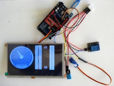
Picture 1, and the Video show the connected and powered up project.
If you power Arduino, you will see the Temperature and Humidity shown on the Display. You can use the buttons to control the Relay, and the Track Bar to control the Servo.
On Picture 2 you can see the complete Visuino diagram.
Attached as ViSiGenieInstructable.zip is the 4D Systems Workshop project I creted for the Tutorial. You can download the 4D Systems Workshop from the 4D Systems site.
Also attached as ViSiGenieDHT11ServoRelayInstructable.zip is the Visuino project, that I created for this Tutorial. You can download and open it in Visuino: https://www.visuino.com
Credits
Related products

Leave your feedback...