
Arduino Color Mixer

About the project
This project will let you have some fun playing with colors using Arduino analog input / output. Change colors with just a twist.
Project info
Difficulty: Easy
Platforms: Arduino
Estimated time: 1 hour
License: GNU General Public License, version 3 or later (GPL3+)
Items used in this project
Hardware components


Story
Arduino Color Mixer
This tutorial is pretty easy and requires a little Arduino and electronics knowledge, if you're not familiar with Arduino, I'll include links to guide you through the tutorial.
In this tutorial we'll generate all the possible colors that you can see with just a twist. It will also make you see through the RGB color model and understanding how today's displays work.
We'll also use Arduino analog Input / Ouput ( referred to as I/O later in tutorial ) and will learn how to read and write analog voltages on Arduino pins.
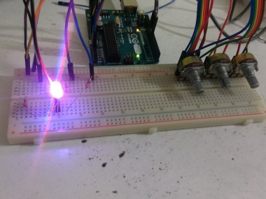
This is my first trial of the circuit ( a while ago, it had a small problem while increasing the pot value but I fixed it later. )
1-1 Components
- Arduino board ( I'm using Arduino Uno )
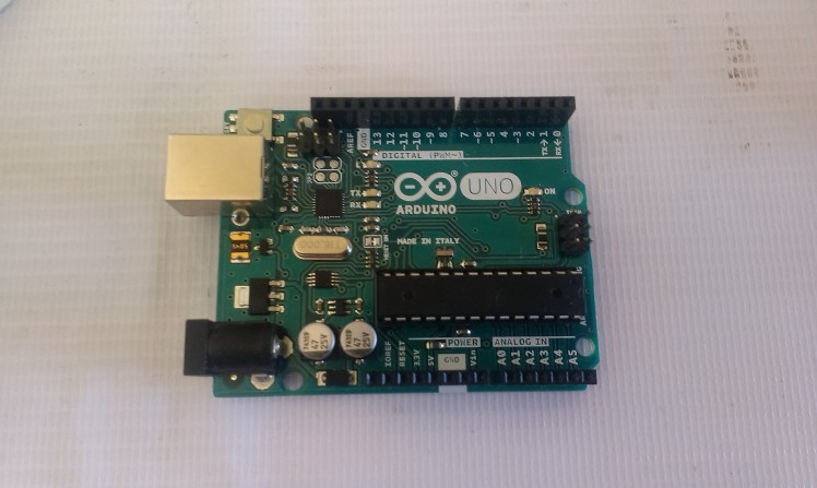 Arduino Uno
- Breadboard
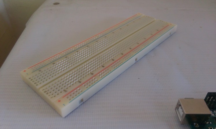 breadboard
- Male-male jumpers ( about 15 )
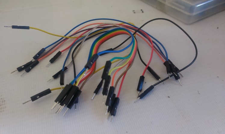 male-male wires
- 3 * Potentiometers ( I'm using 5K pots. )
 potentiometers
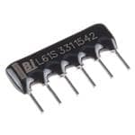
- 3 * 330 Ohm resistors ( orange - orange - brown )
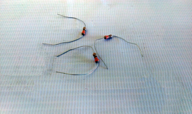 330 Ohm Resistors
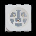
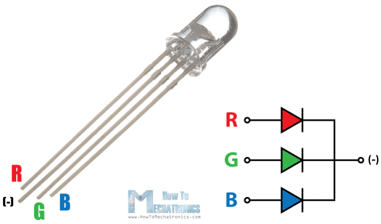
- RGB Led ( RGB Module works also )
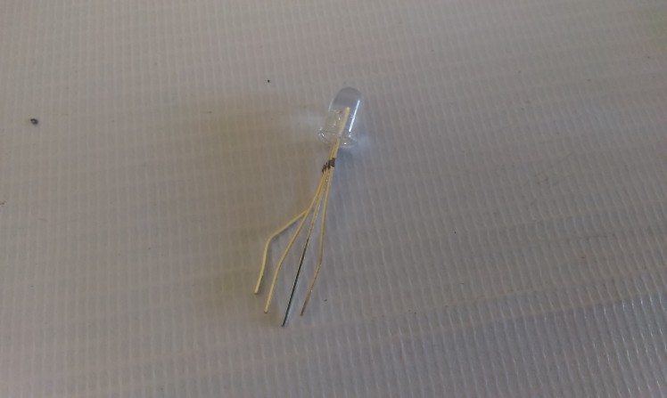 RGB LED
- PC with Ardiuno IDE installed to program the Arduino
Let's Roll !

The idea behind the color mixer is that the Arduino outputs on the RGB LED pins a voltage relative to the input voltage of the potentiometer on the analog inputs.
1-2 Connecting The Pot.
The pot will be our voltage divider circuit, where Vout is the Arduino pin
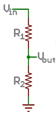 Voltage divider circuit
In a nutshell, it transforms a adjustable amount of the voltage (changes by twisting the rotor) to the Arudino analog input pin ( Vout ) this link explains the topic even further.
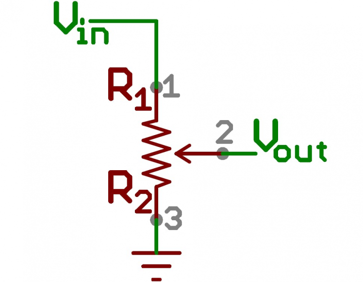 Pot voltage divider
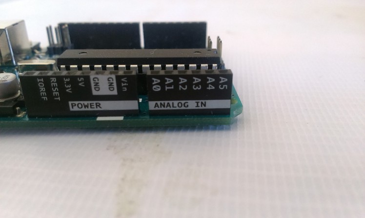 Arduino analog input pins
Connect the pot as illustrated in the image, connecting the outer terminals on either 5v or GND doesn't matter at all, the most important connection is the middle terminal, which goes to the analog input pins.
You obtain the 5v and GND from the Arduino pins.
I'm using the Orange for the 5v ( instead of Red ) to make easier to differentiate between power and signal lines
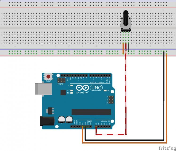 Potentiometer (Pot.) Connection
Repeat this connection for the 3 pots for each color.
I want to keep the connections as tidy as possible so I'll connect the pot for the Red color on A0, Green on A1 and Blue on A2.

1-3 Connecting the RGB LED
The RGB LED uses the same concept of the conventional LED ( diode ) the magic happens because it contains 3 LEDS beside each other, when the light from those LEDs fall on your retina they represent different colors because you view them as a single combined color.
Since we have 256 value for each PWM output and 3 pins that represent Red Green Blue, we have a total of 256 * 256 * 256 colors which is 16,777,216 colors (almost 17 Million).

The RGB Led is connected the same way you'd connect a normal LED but you repeat the work 3 times.
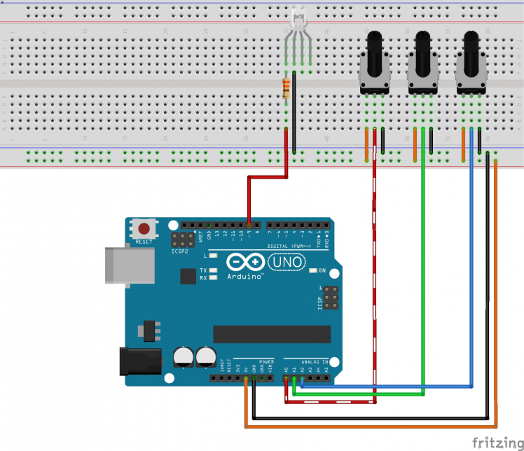 Red LED and ground connected
The final output should look like, I connected the Red value on the lowest pin number in either the input and output pins, just to keep things simple in code.
Don't forget to connect the 330 Ohm resistor because I made this mistake and got my Red LED burnt out electricity won't do much work to get an LED burnt, so take care.
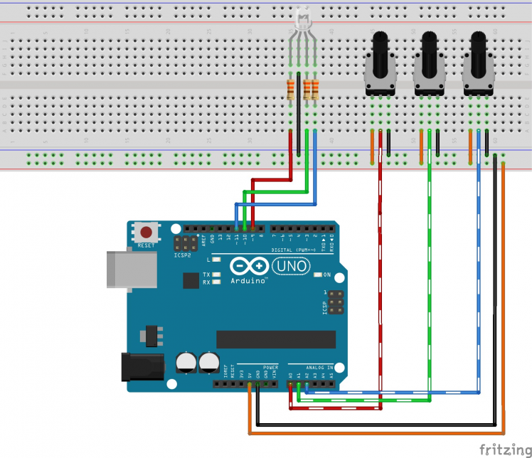 Full circuit breadboard view
Now we have a complete circuit, the code is really so simple and straight forward.

Let's Code
The code of the Arduino does those simple tasks in a sequential manner.
In the Setup
- Set the mode of 3 analog input pins to input
- Set the mode of 3 pwm (analog output) pins to output
In the Loop
- Read the value of the pot. using analogRead function
- Map the value from the analog pin to a matching PWM value using the map
- function
- Write the PWM value to the analog pin using analogWrite function
The code is available below.
my final output don't forget that I burnt the Red LED : -it's connected on the first pot-
Now you have the ultimate color generator with 17M colors! congrats!!
Respect & Share the project it if you like it :)
Check out my other tutorial about making an 2 wheel drive robot using 1Sheeld.
Schematics, diagrams and documents
Code
Credits
Related products


Leave your feedback...