
Arduino Based Coin Sorting And Counting Machine

Made by DIY-Machines / 3D Printing / Sensors
About the project
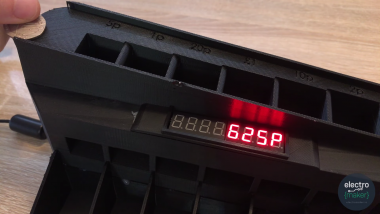
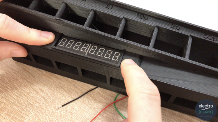
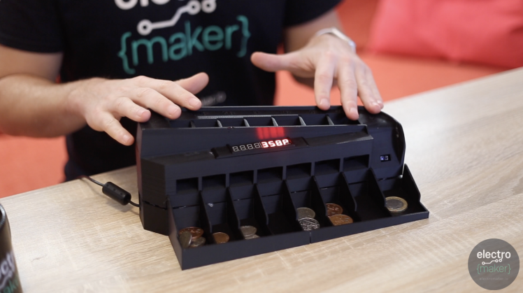
This Arduino powered machine separates coins of different dominations and then tallies up their total value. This is shown on an 8 digit 7 segment display. It is a coin sorter / coin counter machine! Reflected infrared sensors (TCRT5000s) are used to detect the coins.
Project info
Difficulty: Easy
Platforms: Arduino
Estimated time: 2 hours
License: GNU General Public License, version 3 or later (GPL3+)
Items used in this project
Hardware components


Story
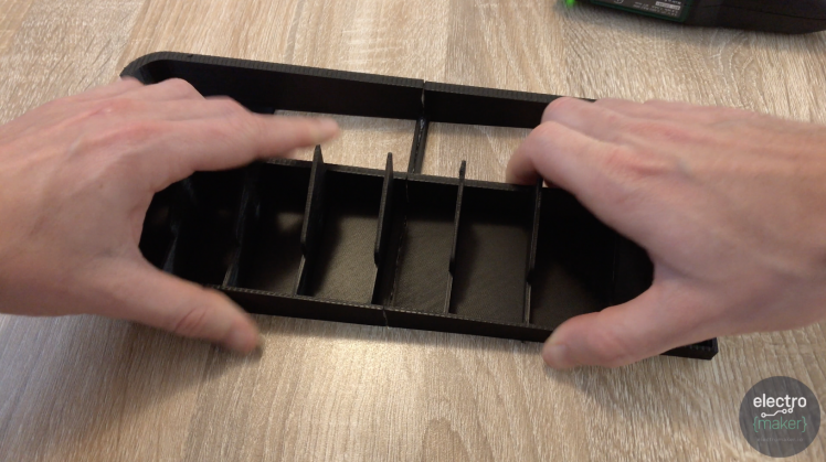
This machine is designed to sort coins based on their physical size and then count them up to calculate their total value as it's sorting them.
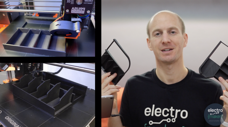
Once you have pulled together your list of parts (see the BOM). You need to begin by printing the main body of the coin sorter.
Have you seen the Skittle Sorter project?

View the project tutorial here!
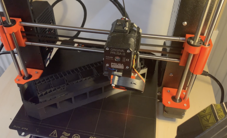
I printed mine at a layer height of 0.15mm which resulted in a print which took some time, but had smooth surfaces for the coins to travel over.
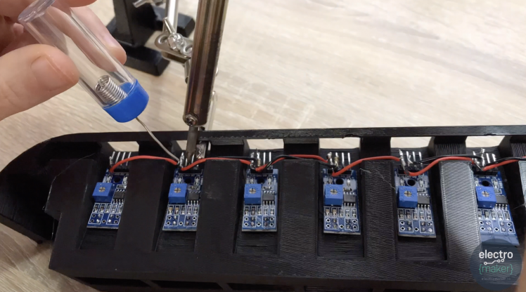
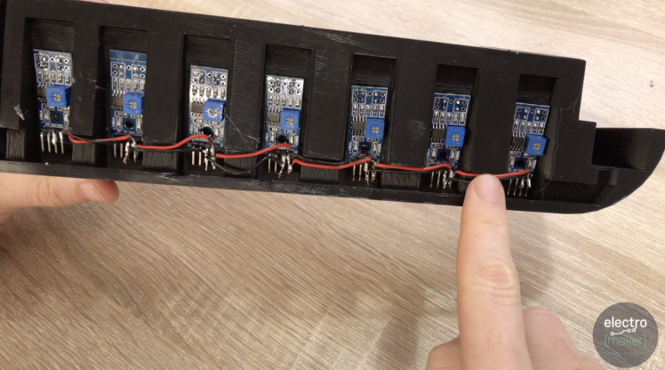
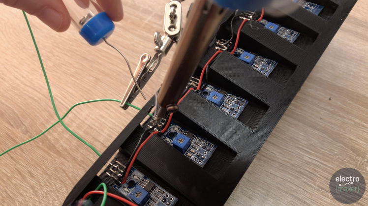
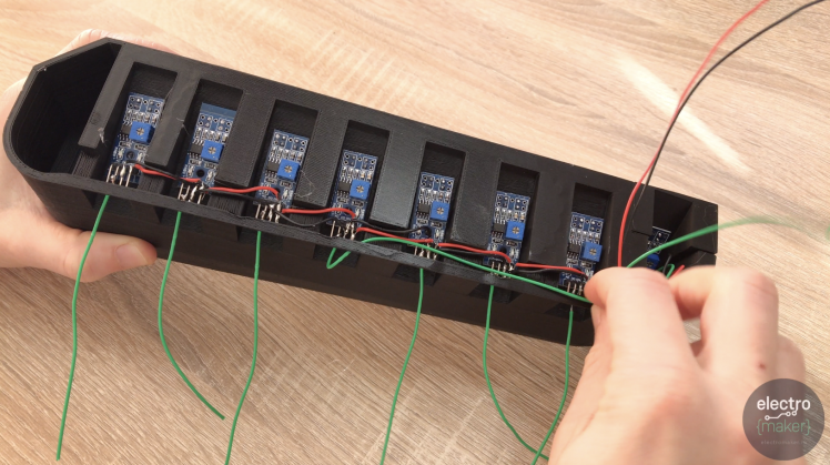
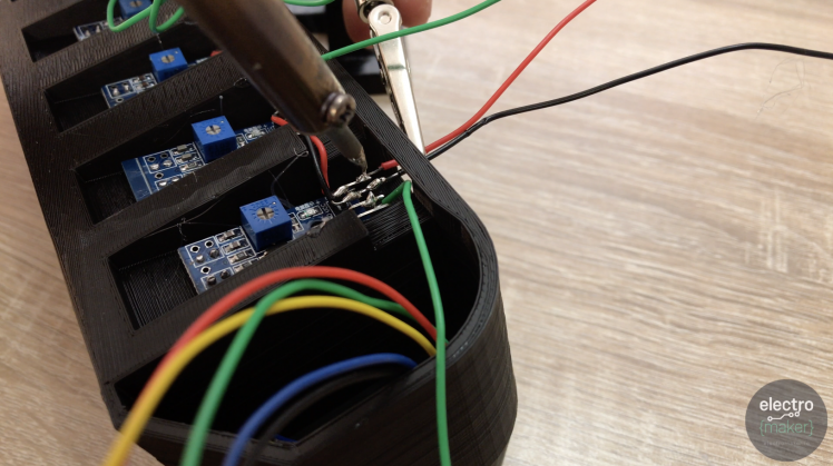
Now we will fix seven of the TCRT5000 chips into position along the bottom of the print. A dab of hot melt glue is all that is required to hold them in place. The positioning is not super important.

We have a limited number of power pins on the Arduino Nano, so to be able to connect all the sensors we will first connect all the VCC pins together of the TCRT5000's we have glued to the body. The same will also be done with their ground pins. This has the effect of wiring them up in parallel to one another.
Use some short (about 4 cm) lengths of wire for this.
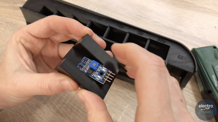
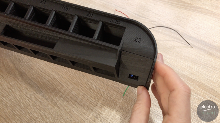
Now we have seven of the sensor fitted we need the slide and sensor housing for the £2 coin (this is another part you'll need to 3D print).

Before we glue this part to the rest of the assembly glue an additional TCRT5000 to it, but this time it will be 'upside down'.
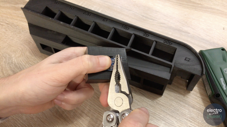
 Now carefully bend the pins on the sensor module. Use a set of pliers for this and move them gently. Avoid moving them back and fourth as they can be easily snapped.

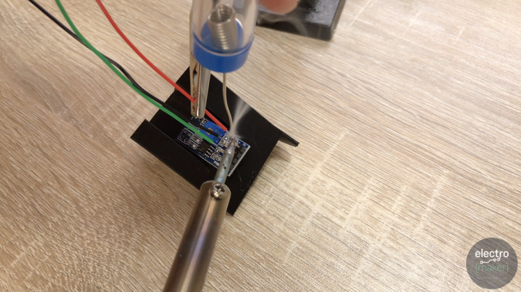
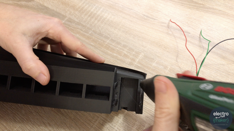
As this sensor module's pins will be hard to work with later we will solder a wire to its VCC, GND and D0 pins now. When you prepare your wire it want's to be about 5cm longer than the length of the main printed body part.
Add some glue to the main body and marry up the complete £2 slide assembly (the one we just attached a sensor module to). When you position it ensure that the top side meets nicely with the path the coin needs to slide along. If it's too high the coin may get stuck.
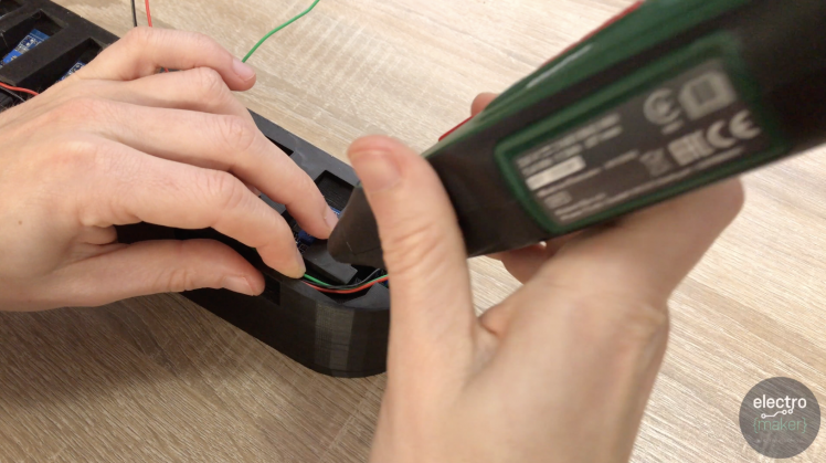
Once the glue has called you can turn the assembly so far upside down and use some more hot glue to hold the wires into place in their channel from the £2 module.
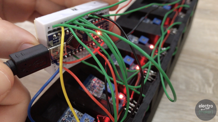
So we now need to go back to our first seven sensors and solder a wire to each of their D0 pins. This is the one which will provide us with a HIGH or LOW reading as it detects coins. Solder each one separately and ensure the wire is long enough to go from the sensor the end with the big void underneath.
This is where our Arduino will be and so the cables need to be long enough to reach it.
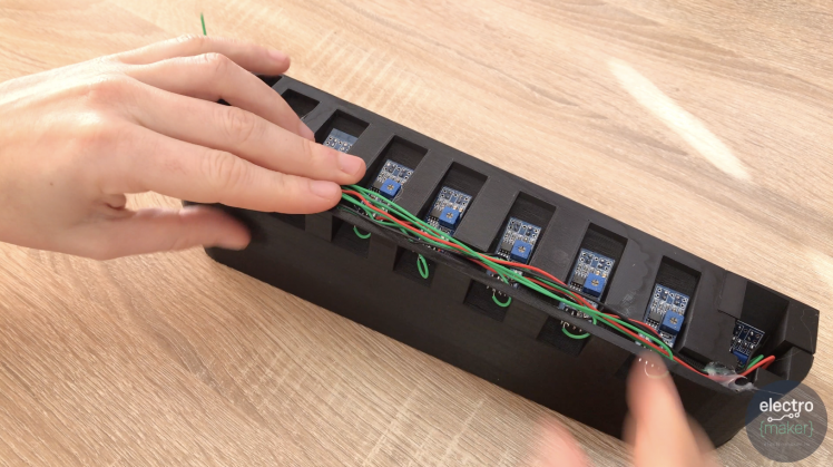
To keep everything tidy we will then pass the sensor wires (green in my example) back through the hole and run them along the channels.
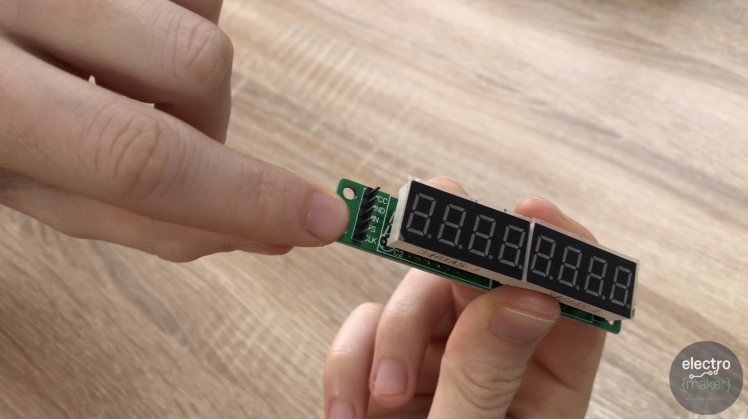
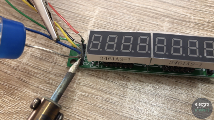
The display module needs 5 wires soldering to its 5 pins. When the module is seated in its final resting position it's the pins on the left (where I am pointing) that we need to solder wires to. They will then be fed down through an internal tunnel towards the Arduino's breadboard.
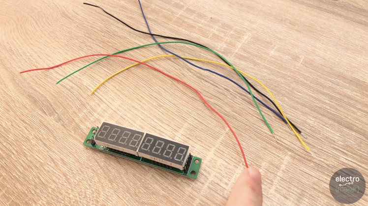
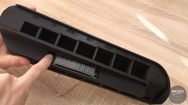
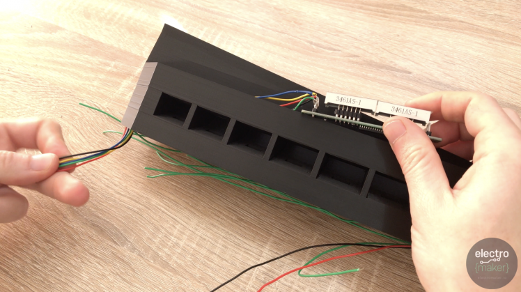
Now we can feed the wires down through he whole where the module will be seated. If you have done all the wires in a single colour then feed them through one at a time and label them as they come through so you know which is which when you come to connect them to the Arduino's breadboard.

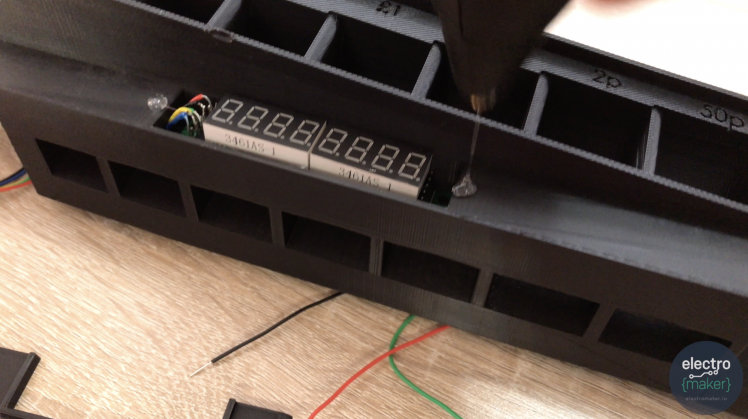
Before we finish dressing the display with a frame, i'd recommend removing the displays protective plastic film (if yours has some).
Print the display frame, and then fix it into place using a little more hot melt glue.
We've got two last wires to solder. This time it's to the VCC and GRND connections of the very first TCRT5000. They already have wires connected to them to all the the other modules. These new wires will be to connect them all up to the Arduino. They want to be about 10cm in length.

Fold these two newest wires back inside the housing as we did with all the other wires earlier.
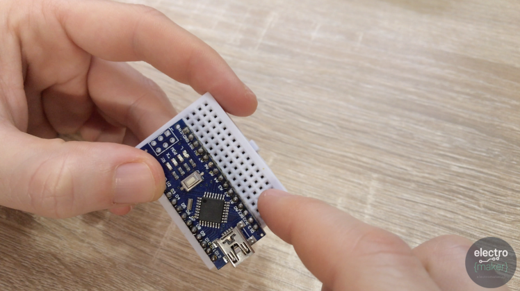
The Arduino Nano needs to be positioned on the breadboard so that we have as many free pins available on the side with the 5v and 3v power connection as possible whilst still having one free row on the other. Take a look at the following image.
Let's connect the wires between the Arduino and Display via the breadboard:
Arduino --> Display Module
D13 --> CLK
D10 --> CS
D11 --> DIN
GND --> GND
5V --> VCC
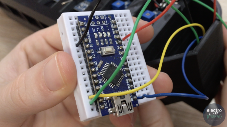
Next you can take the power and ground leads (VCC and GND) from the first TCRT5000 and connect these to 3.3V and GRND on the Arduino. The power connection from our £2 sensor (the one furthest away) also wants to be connected to the same set of pins on the Arduino.
Last but not least we need to connect the wires from coming from the D0 pins of our sensors to their respective pins on the Arduino Uno:
Sensor Value --> Arduino Pin
5p --> D8
1p --> D6
20p --> D5
£1 --> D4
10p --> D2
2p --> D7
50p --> D9
£2 --> D12
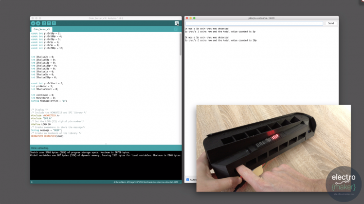
Download a copy of the code from this article, and plug in your Arduino Nano to upload it.
You can download the required library from its GitHub repository:
https://github.com/HobbyComponents/HCMAX7219
(The SPI library is a standard one which comes with the Arduino IDE.)
Once the code has been uploaded, open the Serial Monitor. You can check that everything is working by sticking an object (such as your finger) in the slots for the coins. This should trigger the display and you'll see a running commentary on the serial monitor.
As long as this works as expected we can finish the assembly. Print the two base pieces and glue them together.
Now add some glue around the back perimeter of the base and then fix the main body of the assembly to it. Ensure that the guides for the coins match up along the front of the body. It's also a good idea to do this with the USB cable already connected as it can be tricker to reach the USB port on the Nano once everything has been assembled.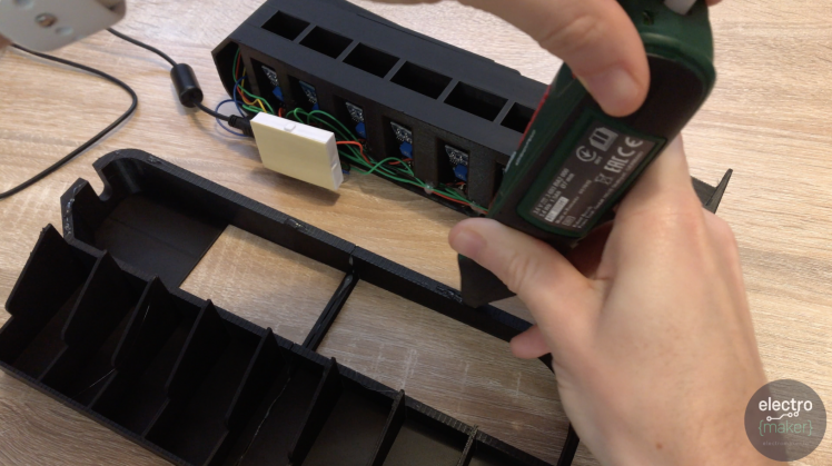
And that's it. Job done, well done!
I hope you enjoyed it. If so please take a look at some of the other projects I've posted here on Electromaker.io.
CAD, enclosures and custom parts
Code
Credits
Related products


Leave your feedback...