
Arduino & Visuino: Control Dc Motor With L9110s Driver

About the project
Arduino controlled DC Motor with L9110S Driver Module - Quick and Easy with Visuino!
Project info
Difficulty: Easy
Estimated time: 1 hour
License: GNU General Public License, version 3 or later (GPL3+)
Items used in this project
Hardware components

Software apps and online services
Story
Brushed DC Motors are often used to drive robots around, or for variety of other cool Arduino projects. To control the motor with Arduino, you usually need to use a motor driver. There are a lot of different motor drivers available. One of the most popular and affordable ones for very small motors are the L9110S Motor Drivers.
Please be aware that this driver board can drive only small motors, with max working current up to 0.8A. If you need more power and bigger motors, you will need a more expensive and powerful motor driver board.
In this Tutorial, I will show you how easy it is to connect and control a DC Motor with a L9110S Dual Motor Driver, by using Visuino.
In the future I also plan to make Tutorial on using more powerful driver boards, so stay tuned.
Components
1 / 3 • Picture 1

Picture 1

Picture 2

Picture 3
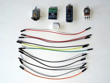
- One Arduino compatible board (I use Arduino Nano, because I have one, but any other will be just fine)
- One L9110S Dual Motor Driver Module
- One small brushed DC Motor(It is highly recommended to have a 0.1uF Capacitor soldered to the motor to reduce noise as shown on Picture 3)
- One 10K Potentiometer
- One small Breadboard (Any breadboard can be used, or any other way to connect 3 wires together)
- 6 Female-Female jumper wires
- 5 Female-Male jumper wires
- Some DC power supply for the motor(Picture 2). I used adjustable power adapter, but a battery or any other DC power supply with the proper voltage will work.
1 / 3 • Picture 1

Picture 1

Picture 2

Picture 3
To make is easier to see the rotation of the motor, I have taped a piece of black insulation tape on the motor shaft.
Since the board can control 2 motors - channel A and B, and we use only one motor for simplicity, here we will connect only channel A. Channel B can be connected and used the same way.
- Connect the Motor to the motor control connection points of channel A of the L9110S Dual Motor Driver (Picture 1)
- Connect Female-Male Ground wire(Black wire) to the Ground pin of the Motor Driver board (Picture 2)
- Connect Female-Female Power wire(Red wire) to the Power pin of the Motor Driver board (Picture 2)
- Connect Female-Female Speed Control wire(Green wire) to the Speed Control(A) pin of channel A of the Motor Driver board (Picture 2)
- Connect Female-Female Direction Control wire(Yellow wire) to the Direction Control(B) pin of channel A of the Motor Driver board (Picture 2)
- Connect the other end of the Speed Control wire(Green wire) to the Digital pin 3 of the Arduino board (Picture 3)
- Connect the other end of the Direction Control wire(Yellow wire) to the Digital pin 2 of the Arduino board (Picture 3)
- Connect another Female-Male Ground wire(Black wire) to the Ground pin of the Arduino board (Picture 3), and leave the Male end unconnected
1 / 2 • Picture 1

Picture 1

Picture 2
- Connect the other end of the Power wire (Red wire) from the Motor Driver to the positive(+) of the power source (Picture 1) - In my case a jack that I connect to the adjustable power adapter
- Connect another Female-Male jumper wire (Black wire) to the negative(-) of the power source (Picture 1) - In my case a jack that I connect to the adjustable power adapter
- Connect the Male ends of the 3 Ground wires (Black wires) - from the Power source, the Motor Driver board, and the Arduino together as example with the help of a Breadboard (Picture 2) - In my case I used a small Breadboard
1 / 3 • Picture 1

Picture 1

Picture 2

Picture 3
- Connect a Female-Female Power wire (Red wire) to the one end pin of the Potentiometer (Picture 1)
- Connect a Female-Female Signal wire (Gray wire) to the Wiper (center) pin of the Potentiometer (Picture 1)
- Connect a Female-Female Ground wire (Black wire) to the other end pin of the Potentiometer (Picture 1)
- Connect the other end of the Ground wire (Black wire) to the Ground pin of the Arduino board (Picture 2)
- Connect the other end of the Power wire (Red wire) to the 5V Power pin of the Arduino board (Picture 2)
- Connect the other end of the Signal wire (Gray wire) to the Analog pin 0 of the Arduino board (Picture 2)
- Picture 3 shows in Red the Arduino Nano pins that were connected in this step. The picture also shows the pins connected in Step 2 in Blue
1 / 2 • Picture 1

Picture 1

Picture 2
Please be aware that there are some critical bugs in Arduino IDE 1.6.6. Make sure that you install 1.6.7 or higher, otherwise this Tutorial will not work!
- Start Visuino as shown in the first picture
- Click on the "Tools" button on the Arduino component (Picture 1) in Visuino
- When the dialog appears, select Arduino Nano as shown in Picture 2
1 / 4 • Picture 1

Picture 1

Picture 2

Picture 3

Picture 4
The "L9110S Dual Motor Driver" component included in Visuino supports 2 channels. Since we will control only one motor we will connect only one of the channels.
- Type "motor" in the Filter box of the Component Toolbox then select the "L9110S Dual Motor Driver" component (Picture 1), and drop it in the design area
- Connect the "Direction(B)" pin of the first channel of the DualMotorDriver1 component to the "Digital" input pin of the "Digital[ 2 ]" channel of the Arduino component (Picture 2)
- Connect the "Speed(A)" pin of the first channel of the DualMotorDriver1 component to the "Analog" input pin of the "Digital[ 3 ]" channel of the Arduino component (Picture 3)
- Connect the "Out" pin of "Digital[ 14 ]/AnalogIn[ 0 ]" channel of the Arduino component to the "In" pin of the first channel of the DualMotorDriver1 component (Picture 4)
1 / 2 • Picture 1

Picture 1

Picture 2
- In Visuino, Press F9 or click on the button shown on Picture 1 to generate the Arduino code, and open the Arduino IDE
- In the Arduino IDE, click on the Upload button, to compile and upload the code (Picture 2)
1 / 2 • Picture 1

Picture 1

Picture 2
Picture 1 shows the connected and powered up project.
If you position the potentiometer in the middle, the motor will stop. If rotate the Potentiometer in one direction the motor will start rotating, and you can use the potentiometer to adjust the speed. If you rotate the potentiometer past the middle point in the other direction, the motor will start rotating in opposite direction.
Congratulations! You are now in full control of your DC Motor :-)
On Picture 2 you can see the complete Visuino diagram.
Also attached is the Visuino project, that I created for this Tutorial. You can download and open it in Visuino: https://www.visuino.com
Credits
Related products


Leave your feedback...