
Arduino: Accelerometer Gyroscope Compass Mpu9250 I2c Sensor

About the project
Connect MPU9250 Accelerometer Gyroscope Compass to Arduino, and show the data in Scope and Visual Instruments in Visuino - Quick and Easy!
Project info
Difficulty: Easy
Estimated time: 1 hour
License: GNU General Public License, version 3 or later (GPL3+)
Items used in this project
Hardware components

Software apps and online services
Story
MPU9250 is one of the most advanced combined Accelerometer, Gyroscope and Compass small size sensors currently available. They have many advanced features, including low pass filtering, motion detection, and even a programmable specialized processor. Having nearly 130 registers however, with many settings, they are also very difficult to work with from code.
Couple of weeks ago GearBest were nice enough to donate a MPU9250 module to sponsor adding support for it in Visuino. It took 2 weeks of hard work, but at the end I not only had the support for MPU9250 implemented, but I also added Acceleration To Angle converter, Complementary (First and Second order), and Kalman filters that can be used with it to improve precision.
This is the first tutorial on the new MPU9250 support in Visuino, and it shows how easy it is to use it with Visuino. In the following tutorials I will show you how you can use the Acceleration To Angle converter, the Complementary and Kalman filters and get really good results from your sensor module.
Step 1: Components
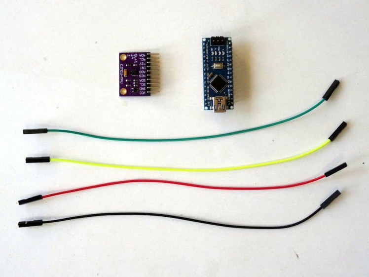
- One Arduino compatible board (I use Arduino Nano, because I have one, but any other will be just fine)
- One MPU9250 Sensor Module (in my case generously donated by GearBest)
- 4 Female-Female jumper wires
1 / 3 • Picture 1

Picture 1

Picture 2

Picture 3
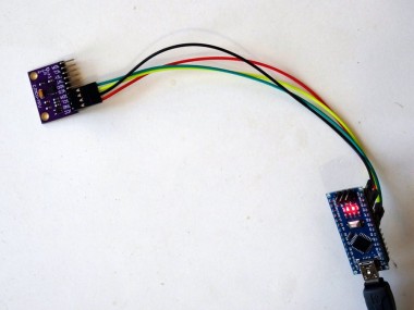
- Connect 5V VCC Power (Red wire), Ground (Black wire), SDA (Green wire), and SCL (Yellow wire), to the MPU9250 Module (Picture 1)
- Connect the other end of the Ground wire (Black wire) to Ground pin of the Arduino board (Picture 2)
- Connect the other end of the 5V VCC Power wire (Red wire) to the 5V power pin of the Arduino board (Picture 2)
- Connect the other end of the SDA wire (Green wire) to SDA/Analog pin 4 of the Arduino Nano board (Picture 2)
- Connect the other end of the SCL wire (Yellow wire) to SCL/Analog pin 5 of the Arduino Nano board (Picture 2)
- Picture 3 shows where are the Ground, 5V Power, SDA/Analog pin 4, and SCL/Analog pin 5, pins of the Arduino Nano
1 / 2 • Picture 1

Picture 1

Picture 2
To start programming the Arduino, you will need to have the Arduino IDE installed from here: http://www.arduino.cc/.
Please be aware that there are some critical bugs in Arduino IDE 1.6.6.
Make sure that you install 1.6.7 or higher, otherwise this Tutorial will not work!
The Visuino: https://www.visuino.com also needs to be installed.
- Start Visuino as shown in the first picture
- Click on the "Tools" button on the Arduino component (Picture 1) in Visuino
- When the dialog appears, select Arduino Nano as shown in Picture 2
1 / 3 • Picture 1

Picture 1

Picture 2

Picture 3
- Type "mpu" in the Filter box of the Component Toolbox then select the "Accelerometer Gyroscope Compass MPU9250 I2C" component (Picture 1), and drop it in the design area (Picture 2)
- Connect the "Out" pin of the Pressure1 component to the to the "In" pin of the I2C channel of the Arduino component (Picture 3)
1 / 2 • Picture 1

Picture 1

Picture 2
To send all the channels data over serial port from Arduino we can use the Packet component to packet the channels together, and display them in the Scope and Gauges in Visuino:
- Type "pack" in the Filter box of the Component Toolbox then select the "Packet" component (Picture 1), and drop it in the design area
- Connect the "Out" output pin of the Packet1 component to the "In" input pin of the "Serial[ 0 ]" channel of the "Arduino"component (Picture 2)
1 / 6 • Picture 1

Picture 1

Picture 2

Picture 3

Picture 4

Picture 5

Picture 6
- Click on the "Tools" button of the Packet1 component (Picture 1)
- In the "Elements" editor select the “Binary Analog” element, and then click on the "" button (Picture 2) to add Analog element
- In the Object Inspector set the "Name" property of the Analog Element to "Compass(X)" (Picture 3)
- In the "Elements" editor select the “Binary Analog” element on the right, and then click on the "" button on the left to add another Analog element
- In the Object Inspector set the "Name" property of the new Analog Element to "Compass(Y)" (Picture 4)
- In the "Elements" editor select the “Binary Analog” element on the right, and then click on the "" button on the left to add another Analog element
- In the Object Inspector set the "Name" property of the new Analog Element to "Compass(Z)" (Picture 5)
- Repeat the same steps to add 7 more Binary Analog elements named "Accelerometer(X)", "Accelerometer(Y)", "Accelerometer(Z)", "Gyroscope(X)", "Gyroscope(Y)", "Gyroscope(Z)" and "Thermometer" (Picture 6)
1 / 4 • Picture 1

Picture 1

Picture 2

Picture 3

Picture 4
The Visuino by default can display the analog elements from the packet component in gauges. It is nice however to display the temperature in Thermometer. Visuino allows customization of the way the analog elements are displayed.
- In the Elements editor, select the last Analog element named "Thermometer" (Picture 1)
- In the Object Inspector select the "Instrument" property and click on the "Arrow Down" button next to its value (Picture 1)
- From the Drop Down box select "Thermometer" (Picture 2)
- In the Object Inspector expand the "Instrument" property, then the "Scale" sub-property (Picture 3)
- In the Object Inspector set the value of the "Auto" sub-property of the "Scale" to False (Picture 3) This will disable the auto scaling for the thermometer
- In the Object Inspector set the "Max" sub-property of the "Scale" to 100 (Picture 4) This will configure the thermometer to have a scale from 0 to 100
1 / 2 • Picture 1

Picture 1

Picture 2
To make sure that Visuino will find the starting point of the packet, we need to have a unique header. The Packet component uses special algorithm to ensure that the header marker does not appear in the data.
- Select the Packet1 component (Picture 1)
- In the Object Inspector expand the "Head Marker"property (Picture 1)
- In the Object Inspector click on the "..." button (Picture 1)
- In the Bytes editor type some numbers, as example 55 55
- Click on the OK button to confirm and close the editor
1 / 4 • Picture 1

Picture 1

Picture 2

Picture 3

Picture 4
- Click in the "Out" box containing the pins of the "Compass" of the AccelerometerGyroscopeCompass1 component to start connecting all the Out pins at once (Picture 1)
- Move the mouse over the "In" pin of the "Elements.Compass(X)" element of the Packet1 component. The Visuino will automatically spread the wires so they will connect correctly to the rest of the pins (Picture 1)
- Click in the "Out" box containing the pins of the "Accelerometer" of the AccelerometerGyroscopeCompass1 component to start connecting all the Out pins at once (Picture 2)
- Move the mouse over the "In" pin of the "Elements.Accelerometer(X)" element of the Packet1 component. The Visuino will automatically spread the wires so they will connect correctly to the rest of the pins (Picture 2)
- Click in the "Out" box containing the pins of the "Gyroscope" of the AccelerometerGyroscopeCompass1 component to start connecting all the Out pins at once (Picture 3)
- Move the mouse over the "In" pin of the "Elements.Gyroscope(X)" element of the Packet1 component. The Visuino will automatically spread the wires so they will connect correctly to the rest of the pins (Picture 3)
- Connect the "Out" pin of the "Thermometer" of the AccelerometerGyroscopeCompass1 component to the "In" pin of the "Elements.Thermometer" input pin of the Packet1 component (Picture 4)
1 / 2 • Picture 1

Picture 1

Picture 2
- In Visuino, Press F9 or click on the button shown on Picture 1 to generate the Arduino code, and open the Arduino IDE
- In the Arduino IDE, click on the Upload button, to compile and upload the code (Picture 2)
1 / 5 • Picture 1

Picture 1

Picture 2

Picture 3

Picture 4

Picture 5
- In Visuino select the ComPort, and then click on the "Format:" drop down box, and select Packet1 (Picture 1)
- Click on the "Connect" button (Picture 1)
- If you select the "Scope" tab, you will see the the Scope plotting the X,Y,Z values from the Accelerometer, Gyroscope, and Compass, as well as the Temperature over time (Picture 2)
- If you select the "Instruments" tab, you will see the Thermometer and the Gauges showing the same information (Picture 3)
You can see the connected and running MPU9250 Accelerometer, Gyroscope and Compass sensor on Picture 4.
Congratulations! You have created a MPU9250 Accelerometer, Gyroscope and Compass measuring project in Arduino, with Visual Instrumentation.
On Picture 5 you can see the complete Visuino diagram.
Also attached is the Visuino project, that I created for this Tutorial. You can download and open it in Visuino: https://www.visuino.com
Credits
Related products


Leave your feedback...