
Aquariumatic

Made by craighissett / Animals / Home Automation / IoT
About the project
Automated aquarium monitor with Web GUI. daisychain units can control multiple tank all from the one master unit. PI/Arduino/ESP Powered
Project info
Difficulty: Easy
Platforms: Arduino, Raspberry Pi, Linux
Estimated time: 5 hours
License: GNU General Public License, version 3 or later (GPL3+)
Items used in this project
Hardware components


View all
Story

Details
The initial plan was something like this:
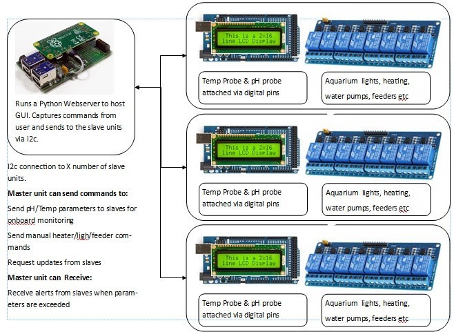
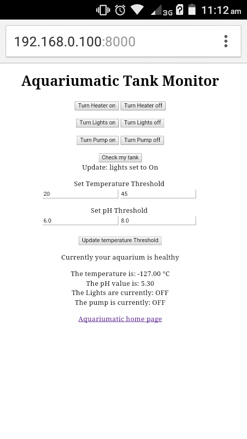
The aim was to use a Raspberry Pi as a Webserving i2c master. This would provide a user interface accessible over the network on any device, and also the ability to relay commands to multiple i2c devices.
These slave devices contain Arduino Nanos operating as i2c slaves, with multiple relays (for controlling a tank's lights, heaters, pumps etc) and also pH and Temperature sensors for monitoring the tank's current state.
All data collected by the Slaves would be returned to the master when requested for display on the web GUI when the page is requested. For example if the user were to access page /23 on the web interface the device would make a request to the slave configured for Tank 23.
In theory I would like the master to be able to provide a set of parameters to the slave; things such as temperature and pH thresholds, to be saved to the Arduino's EEPROM. This would allow the arduino to constantly monitor the Tank's state and respond to some any anomolies:
- Trigger the heater if the temperature drops below the provided threshold
- Send warning messages back to the Pi if anything is amiss.
This would allow the user to preset configure each individual slave for the type of fish they are keeping in that tank. Ideal for a multi tank setup, or even a pet store.
----------CURRENT PLAN----------
While the plan has not changed, the way in which I hope to achieve the functions required has evolved following lots of trial and error and also following me picking up a great deal of practice using wifi communication.
As a result the following updates have been made to the project:
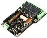
- The arduino in the slave device has been changed to a Wemos D1. It retains the Uno footprint required for use with the enclosure we are using, but enables WiFi to be used as a comms protocol
- i2c is no longer required for linking the Pi (the 'Hub') to the Slaves (the 'Control Units'); The Hub will use a USB Dongle in AP mode alongside it's onboard Wifi, and the ESP8266-powered Control Units will connect to this AP.
- The Control Units no longer require the Hub to operate; the Units will now server their own simple web GUI to allow for standalone use (great for home use).
- The Control Units will also host the >
Parts Acquisition and demo build
First and Foremost Merry Christmas!
Just a quick update regarding this project.
I have been accumulating all the parts I require to build a portable demo rig of this project and it has took some time. Today I have finally ordered the last pieces to be able to finish off this rig on my return to work in the New Year.
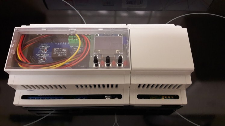
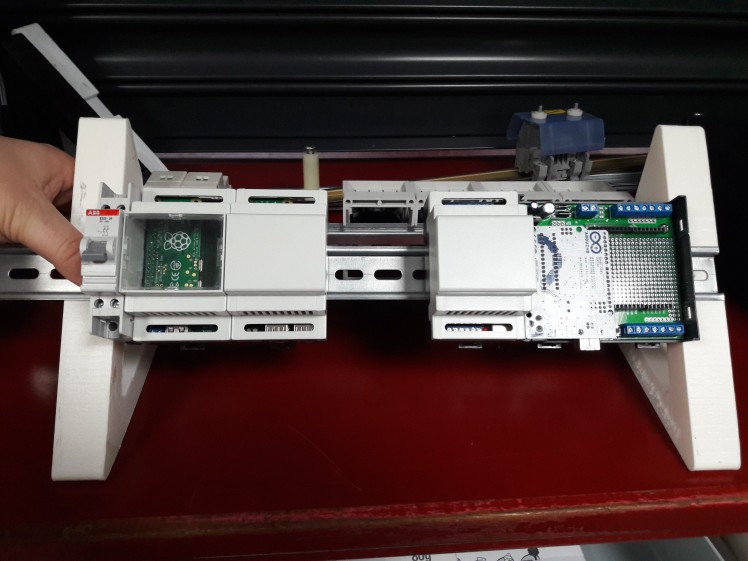
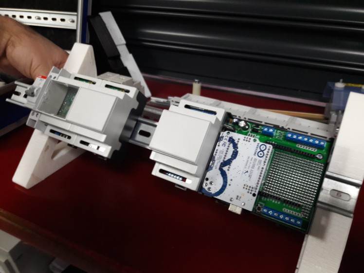
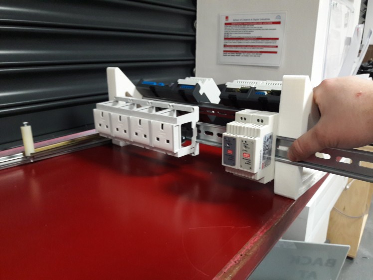
The rig is going to be built upon a two DIN rail system mounted to two triangular mounts; the front rail will hold the Pi, Arduino and relay modules, and the back rail will hold the mains power distribution, 12v power supply, 5v power supply and 4 rail mountable 13A sockets.
This will keep the project small and compact, will keep the wiring neat and hidden between the rails, and will look great on my desk :-)
If space allows I am also going to mount the original Aquariumatic slave module that only worked via USB, and I will rewrite the old code for the unit to be supported on the current Pi. It'll allow me to show the progression of the project.
Pics will come in the new year; all parts apart from the 13A socket are currently in my possession so we are good to get going!
Marching on
Tonight has been a long but rewarding session. Spent the last few hours writing and rewriting functions for my #Aquariumatic project. Tonight's focus has been how data is shared amongst devices in the setup.
Previously the setup focussed on the slave units sharing JSON packets (containing temperature, pH and other sensor information, relay states and other device information) to a webserver to be displayed to the user in a web page. This was slow development; the first device was built around an Arduino uno and used serial to send data (very messily before I started using json), and has steadily improved as I've learned more.
Following tonight's work the JSON packets have been heavily formatted and are now fully compatible with the MQTT scripting I have also been working on, as well as dislayable on a simple webpage served by the Unit itself for standalone operation. Now I have got this part playing nicely I can reinstate the rest of the functionality to the unit and can finally say the slave unit software is complete.
I have also been working hard on the Hub(server/broker) Unit that will tie all the slaves together, and have a cracking setup based on the DietPi os. Once this is finished I'll be able to leave the software and turn my attention to getting the prototyped units recreating in product form.
Earlier in the week I submitted proposal to a manufacture to try and turn my prototypes onto finished products.
I cannot effing wait!
Development update
Tonight I've had a bit of time to have a look at how to reinforce my network communication between the various units that could be used to make up an Aquariumatic install.
After hearing a lot about MQTT (and subsequently watching a lot of related videos) I decided that integrating the protocol would improve my communication between not only the devices but the user.
I have installed an MQTT Broker (like a server) onto a Pi and it runs great. I'll be able to run this on the Pi Powered hub in my setup. The original plan was to go figure the Pi as an Access Point and have all the devices connect to it; this is great, as all the devices will have access to the broker.
I've also had an MQTT client running on an ESP8266, successfully publishing >@Hartmut Wendt . These units will demo my #Aquariumatic setup and also my General Home Automation core. I'd like to add some more units to this rail to demonstrate the multi-unit wireless setup that is capable with both projects.
The bottom rail will contain all power and on/off switches to the left of the rail, and the rest of the rail will be dedicated to other projects (such as this Pi/4xRelay/LCD build I'm going to use to simulate the Bin Sensor unit I currently have running in a factory for testing). For power (for now) I'm going to be running power into the switch, then to the two variable power supplies (set at 12v and 5v) and then split to all the units in the case.I'll then look to add some covering to mask the cable runs.Happy with today's Progress, I must say!
Demo rig Update
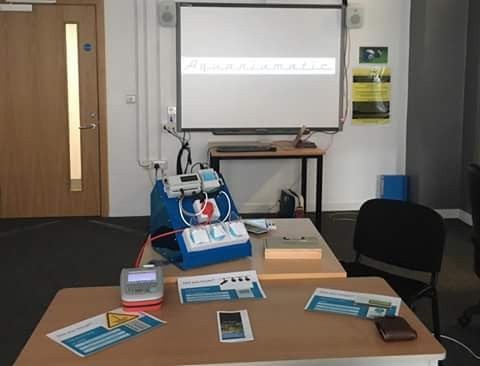
in past posts I have alluded to the idea of creating a portable 'demo rig' for the Aquariumatic; a fully functional setup that is easily portable and can be quickly set up to demonstrate to anyone who is interested in seeing the system work.
I have finally settled on an idea to build up such a case, and will be getting stardom on it next week hopefully.
The case itself is a small blue flight case with a workable width of around 16", and the plan is to mount a DIN rail in the lid of the case and one in the Base of the case. The rail in the lid will hold the Aquariumatic setup of one Control unit and also on Pi Hub unit; when the case is opened it will be easily displayed.
This rail will be powered by a DIN rail variable power supply.
the rail in the Base of the case will hold a switch, another variable power supply and have space to add further components.
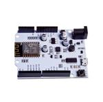
I am also going to fit some additional Wemos D1 boards with arduino lcd Shields to act as dummy control units. These will be handy when demonstrating how the Pi Hub handles multiple tank >A month or two ago I was lucky enough to he selected to trial the titular wifi module by dfrobot:
I applied for the review programme as I was looking for some simple methods of adding wifi to my arduino-based control unit. The module came a while ago, but I chose to order a Bee-compatible Arduino shield to make connecting the board to the Arduino easy. To test the module out I am going to add it to an Arduino Uno with a Nokia display shield to create a 'test control unit' to fire sample data to my Hub unit when demonstrating my multi-tank setup:
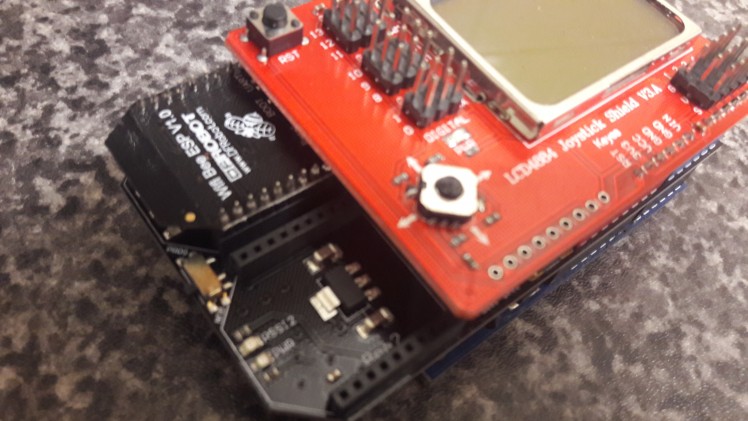
Using the WiFi Bee is fantastically simple when using Bee-compatible boards; just plug it in. Although it has a lot of pins I was relieved to find it only uses a handful; 3.3v, ground, and two pins for serial.
The shield I have bought in the above picture has two Bee ports; one for connecting to the hardware serial port on the Arduino, and one for connecting to a software serial port.
I have opted to use a software serial port for it, leaving the hardware serial port clear for uploading sketches without having to remove it.
Next step I will tweak my code to work with the Uno (currently written for a Wemos D1) and report my findings here.
If the code is easily tweaked I may opt to use my Arduino back in the control unit and use the Wifi Bee for wifi communication. The Arduino enclosure I am using (the ArduiBox by @Hartmut Wendt ) features a nice open prototyping area meaning i could easily solder the Bee in and use it along with my Relay shield.
So far - loving it!
Software work continues
I've been quiet for quite a while on here, but work is still underway.
I have been focusing on writing and rewriting the sketches for the monitor units; at the moment the units work using a Wemos D1 to monitor sensors and relays, display the data on a simple Web page and also serve the data on a json page.
This means the monitors can operate standalone (for home use or for single tank operation) but can also operate as part of a network of monitors via the Pi-powered hub.
I've written a nice little python function which is capable of scraping json data from the json pages. This means I can easily get hold of each monitor 's data for display on a single Web page, and can also be easily uploaded to anot iot site.
I will aim to post more regularly!
Wemos Uno Pins
This is just a quick map to show how the pins differ on the Wemos D1 compared to the Arduino Uno.
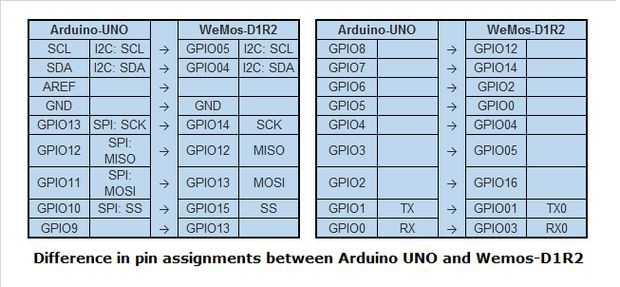
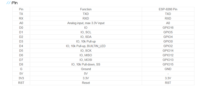
They share the same footprint but their pins are somewhat different.
For my project I need to work out which Pins trigger the relay shield's 4 relays and also the maps for the remaining digital pins for connecting the pH sensor and temperature sensors.
the i2c pins are also required for running the oled screen and buttons.
Work is underway with the Wemos D1 code. The device will run a webserver to display href="https://hackaday.io/hacker/103958">@Hartmut Wendt:

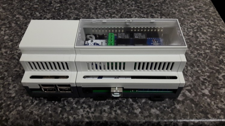
This thing is going to look incredible when mounted in it's display case on the DIN rail!
The DIN rail power supply has arrived today, so I can hopefully start to put together my case as soon as I have the rail fitted.
Mains will be connected to an on/off switch I have, and that switcxh will route the power to the relays and also to the power supply. The power supply will then power the Pi Zero W-based Hub and the Wemos-based Control Unit.
:-)
Process Report
Currently I have the following:
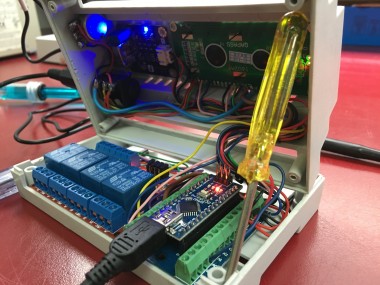
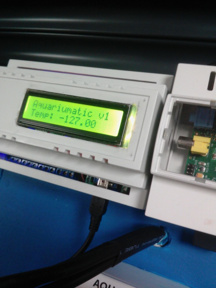
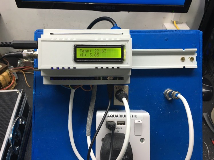
Pi Zero W in DIN enclosure
Wemos D1 in DIN enclosure w/oled display and relay shield
DIN on/off switch
Currently on order awaiting delivery:
DIN power supply
DIN rail
DIN brackets
In order to make this iteration of the Aquariumatic look the absolute balls I'm going to mount a rail in a small flight case on some angled brackets. This will look great for presentation and also will allow it to be really transportable.
Oled screen arrived!
Today is another good day.
My oled add-on screen for my Arduino enclosure from Hartmut Wendt has arrived.
Great service from Hartmut - the first one didn't arrive so was quick to repost.
The screen has 3 buttons with the screen, meaning ingredients I can add a small onboard menu for toggling displayed href="https://hackaday.io/project/19717">#GBAA: Game Boy Advance Arduino project.
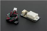
- An ESP-07 based serial port board for my #Arduino Mega Expansion board
- And, for my #Aquariumatic, a few ESP-01 modules to use as plug-in modules.
The ESP-01 has a nice small header, so will take up little real estate on any pcb designs as they materialise. This will give me a great platform to work on my new target of websocket communication with my prototypes once the chips arrive.
Good times!
Protocol
This is just a small update regarding a change of tact regarding communication for the Aquariumatic.
My Arduibox arrived:
Here it is pictured alongside my Pi Zero case. I love it! I am currently testing the configurations of lcd shield, relay shield etc. I think it's looking like both Shields will be dropped and just a standard 4 channel relay module added (screws and spacers added to the Arduibox prototyping area). With regards to the screen I feel like I may end up purchasing the oled add-on module available from Hartmut to keep the device looking so clean.
So, protocol - up until this very point the plan has always been to use i2c to chain my units together; nice and easy, and addresses for 112 devices to be linked together. As a secondary form of communication the pcb was going to carry an esp8266, connected to the Nano via serial, for an additional way of getting href="https://hackaday.io/hacker/103958">@Hartmut Wendt and his awesome Arduibox comes in!
Hartmut has a range of amazing DIN rail enclosures for Raspberry Pi and Arduino available on his webshop. I was lucky enough to get sent a prototype for his Pi zero-based one, and have running a demo webserver on it ever since.
I have just ordered Hartmut's Arduino box enclosure; it takes an Arduino Zero and a shield, while still leaving space for prototyping and extra components.
I have also ordered a relay shield for arduino, and an extra lcd shield too.
I'm going to experiment with using the lcd shield in the case and trying to fit a 4 channel relay module in the case too.
If that doesn't work I will switch to using the relay shield and an alternative screen. Hartmut has just released a fantastic i2c OLED module board that can be added to any of his enclosures, so I will look to order one of those and explore how to use it using a software i2c on the arduino (keeping the main i2c bus free for just master and slave unit addresses).
Cheers!
Arduino Software i2c library
This is just a note to myself really :-)
In order to simplify the chaining of slaves to master I wanted to keep the i2c bus free of any devices other than the slave units (the arduino nanos).
Using i2c displays on the same bus would complicate the process; each slave having two i2c addresses, the screens all carrying the same address etc.
The ideal solution would be to use a library such as this one to create a second bus, just for the screen. this second bus cpild also be used for any further i2c devices added to the slave unit if necessary.
PCB Thinkings
I've been having a think about what kind of layout I'd like for my components to have on a PCB if I ever learn how to create them.
The plan is to have the Nano and Pi's USB ports available via the top/side for serial access/programming etc, with the relay and sensor outputs (and power) ins and outs via the bottom:
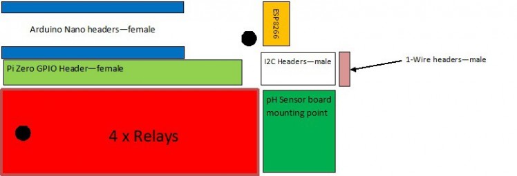
Arduino Nano (Blue Headers)
Either female headers or soldered directly to the PCB, connected to i2c bus (A4/A5), software serial (pins 2,3?) to ESP8266 header, relays (4,5,6,7?) and pH/one-wire sensors (use A1/A2?). 5v Power & Ground
Pi Zero (Light Green Header)
40pin Female header to allow Pi to mount over the top of the the Nano; if the Nano is mounted directly to the PCB there should be clearance to do so.
The only connections for the Pi are to 5v, GND, and i2c Bus. Full header only really required for a sturdy mount, so to speak.
Relays (Red zone)
Potentially a four channel Relay board mounted, or 4 individual relays or fets. TBC
ESP8266 (Orange Headers)
Female headers for mounting an ESP8266.
Connected via serial pins to the Arduino's Software serial pins, and also power and ground. 5v tolerant ESP module would be ideal, or tie it to the Arduino's 3.3v pin.
i2c Headers (White block)
breakout pins for 5v, Ground, SDA and SDL. For connecting LCD Screen and other modules.
1 Wire headers (Awful pinky colour)
Header for Power, GND and 1-wire data pin (A1?). To be used with temp sensors.
pH Sensor Board (Green block)
a mounting point for the standard pH sensor breakout boards with the BNC connectors.
Power, Ground and data (A0) pins to be made available for this module.
LCD Mounting holes (Black spots)
These are to insert spacers for the LCD screen.
Next step - to actually take some measurements and see if this will work!
Also need to draw up a proper pin connection list too.
Software Serial Options
In addition to the rest of the ideas I have for communication I want to add one more thing; a flexible software serial header.
This is to serve as an extra port for communication and control of a slave unit's Nano. This port will mirror everything sent monitored in Nano's code. this can be used in severbal ways, such as:
USB serial cable - for streaming data to a serial window on a PC/Laptop serial monitor, and for manually updating thresholds.
With a Bluetooth module - to allow the same as above but perhaps with a phone/tablet app
With an ESP8266 module - an ESP module could be used in many ways; to host a basic standalone webserver in the bounce of a master unit, to allow wireless comms as the methods above, or even to stream data to IoT sites such as thingspeak :-)
Communication Protocol
i2c is going to be a big part of this project.
Each device will be have the means to monitor a tank; a pH sensor, temperature sensors, relays to control lights, heat and pumps, an lcd screen for displaying tank status, and anew arduino nano to coordinate it all.
In the instance of the master unit it will also have a Pi Zero to host the Webserver and request values from the Nano via i2c to display on that tank's page.
One thing I would love to do is daisy chain several slave devices to one 'master' unit; the Raspberry Pi in the master unit could request status updates from each of the attached slave Nanos for display whenever that tank's Web page is loaded. the Pi could also send commands to the slaves to put ad hoc messages on the screen, or update the thresholds for the monitoring of pH and temperature (thresholds being stored on the Nano's Eprom).
One thing I would like to explore is using a 'software i2c' on the arduino. this would allow the arduino to control the lcd display on its own i2c bus and leave the main, 'proper' i2c for Pi/Arduino communication.
Code
Credits
Related products


Leave your feedback...