
Custom Smart Plug - Controlling A Space Heater With Ecobee

Made by AllPartsCombined / Home Automation / IoT
About the project
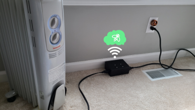
With a relay, you can control your household devices. And with the right data, they can be automated. Here I use Ecobee's API to get the temperature from a room sensor, then use that to control a space heater. This regulates the temperature in a room with poor airflow. The same process can be applied to many project ideas.
Project info
Difficulty: Moderate
Platforms: Arduino
Estimated time: 1 day
License: GNU General Public License, version 3 or later (GPL3+)
Items used in this project
Hardware components

View all
Software apps and online services
Hand tools and fabrication machines
Story
*If you prefer a video tutorial, jump down to the bottom.
*This project involves working with high voltages and high current. Use caution. Do not attempt unless you are comfortable with this.
The Idea
My son's nursery is one of those rooms at the far end of the house where the heating barely reaches. We have an Ecobee thermostat with multiple room sensors, but that doesn't help much when the vent is putting out room-temp air, and it just ends up overheating the rest of the house.
 (My son, trying to sleep every night in his cold nursery)
Step 2 was to add a borrowed space heater, an older model, but even on low, it ended up making the small nursery too warm.
Of course, I could have bought an upgraded heater with a built in thermostat, but why not spend that money on parts to build a custom smart controller that integrates the Ecobee? Because it's still pretty expensive, you say? Well, that's not going to stop an engineer with an design in mind.
Speaking of designs, this is the block diagram I first drew up:
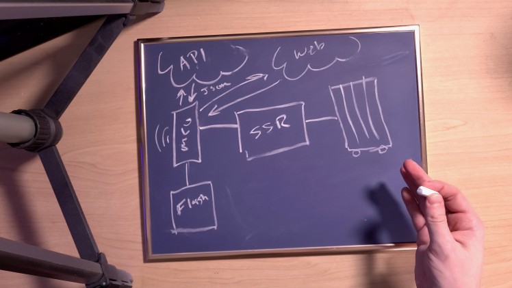
Let me try to break that down for you. There is a Wi-Fi connected microcontroller (MCU) that is communicating with Ecobee's API, receiving data formatted as JSON, which is decoded to get the temperature. Based on this, it uses a Solid State Relay (SSR) to control the heater (crudely drawn on the right). Also, the MCU is saving data to its built-in flash memory, and it hosts a web server (Web) with configuration controls and a log dump. Make sense?
Note: After the first prototype, I ditched the SSR for a mechanical relay. It was generating way too much heat to feel comfortable leaving it in the nursery overnight.
I chose a NodeMCU ESP8266 for the microcontroller so I'd have built-in Wi-Fi.
Circuit Diagram
After that, I refined the design into a detailed schematic (I'll use the term "refined" lightly, since I still drew it in MS Paint).
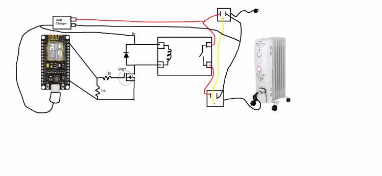
This is the version with the mechanical relay. Notice that the relay can't be driven by the microcontroller alone, so there is an NFET transistor driver circuit that pulls power from a USB phone charger. Info about how that circuit works can be found here: https://arduinodiy.wordpress.com/2015/12/29/using-fets-to-switch-a-load/
The microcontroller itself is also powered by a phone charger - I managed to find a micro-USB splitter cable, and I use one end to power the microcontroller and cut the other end to wire to the driver circuit. I clamped some wire connectors to the prongs of the phone charger and hard wired it to the socket that plugs into the wall.
Software
Then it was just a matter of writing code and putting it all together.
In short, every 5 minutes the microcontroller accesses Ecobee's API to get temperature data. It may receive an error that my authentication tokens are expired (those are used to prove that I'm really supposed to have access to that particular thermostat). If they have expired, I send another API request to refresh them. I save those tokens and some other configuration info (current temperature, some timer settings, etc) to flash memory - this way, if I ever unplug the device, I don't lose important data. Meanwhile, the microcontroller is also hosting a web server of its own with fields to configure settings and a log page (so I can monitor how everything is working and check on any errors that may have occurred). There is also a timer and a few other features.
Grab the code from the repo if you're curious, and see the video below for more detailed explanations about some of the code functionality.
Future Work
There is certainly some room for improvement here. For one thing, the code is all synchronous, meaning that if the processor is tied up waiting on an API request, the Web Server will be inaccessible until it finishes. Also, in some places of the code I pull the actual time from online, and in other places I use an internal timer library. This could probably be consolidated so that all actions are based on real time - the internal timer also gets blocked by API requests, so timing ends up being inconsistent. I may also wire in a fuse as an extra bit of safety.
How To Build It
If you want to build this project as-is, here's what you do.
- You'll need to go to Ecobee's site to register your device and set up an App. I'll let them explain it here: https://www.ecobee.com/home/developer/api/introduction/index.shtml (save the AppId and access tokens you get from them).
- Clone the project repository.
- Unzip the Data folder in the same directory as the Arduino code (.ino file).
- Edit the ssid and password variables in the code with your own WiFi login info.
- Edit the appId variable using the AppID you got from ecobee.
- Copy the access and refresh tokens you got from ecobee into their respective files in the Data folder.
- Replace the contents of the sensor.txt file with the ecobee Sensor name you are using.
- Install the ESP8266 Sketch Data Upload tool.
- Use that tool to upload the contents of the data folder to memory on the microcontroller.
- Upload the sketch to the microcontroller.
- Wire up the circuit based on the schematic (see video below for some construction methods).
- Use the Serial Monitor in the Arduino IDE to monitor the code execution, and it will tell you the IP address of the device. Consider making this a static address through your router settings.
- Copy that address to a browser, and you can access the config/log web server.
- Mount the circuitry in a box, and you're done.Tip: To cut square holes in the enclosure, I cut an X from corner to corner with a hot knife, then score the perimeter with a utility knife, then snap the triangle flaps out.
Conclusion
This is a fairly specific application, but I intended for this project to serve as a template for any Smart Home/Internet of Things device you might want to build. Use what I've written to access any other API and deserialize the data it sends you. Then use that data to control whatever devices you want. The relay can handle turning stuff on or off, but maybe replace that with a motor or a LED screen. You could even gather data from one API and use it to send signals to another API - creating custom Smart Home actions.
Video
And as promised, here is a video of the full design/build/test process.
Schematics, diagrams and documents
Code
Credits
Related products


Leave your feedback...