
Alexa/adruino/pi Smart Electric Water Heater

Made by electrouser1569 / Home Automation
About the project
Save money on your electric bill using Alexa and some mad IoT skillz. Like a Nest for your water heater.
Project info
Difficulty: Difficult
Platforms: Amazon Alexa, Amazon Web Services, Digilent, Everything ESP, Microsoft, Raspberry Pi, RobotGeek, Texas Instruments
Estimated time: 2 days
License: GNU General Public License, version 3 or later (GPL3+)
Items used in this project
Hardware components


View all
Software apps and online services
View all
Hand tools and fabrication machines
Story
Videos
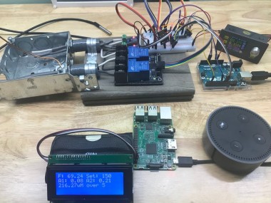
Let's start with some videos that will obviously be covered in depth if you follow along through the whole project. This first video may be a little boring, but hey, it's where it all starts. Watch as the various components come online and get connected up. Go ahead! Kick it up to HD 1080! Thrilling! :)
Booting up the componentsThis next video is a little more fun... Let's watch as Alexa (I call mine "Computer") changes the target temperature and the system reacts.
Exercising the SystemOff the bench and on the water heater! Look out! That 220 can kill ya dead!
Wiring the SmartWater Controller to an Electric Water HeaterThe Genesis
My water heater is the second most expensive appliance in my house next to HVAC. Alexa is my favorite household appliance. Why not use Alexa to help manage my water heater power usage and save money!
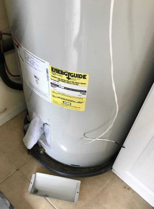
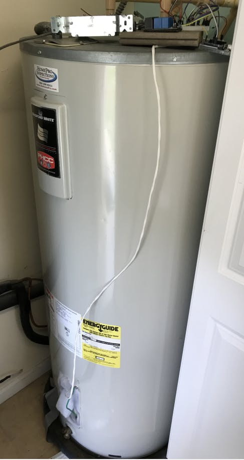
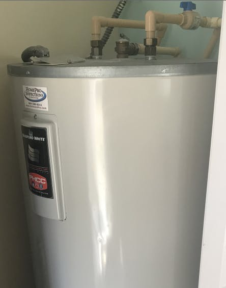 This really is my hot water heater
Non-functional Requirements
- Secure - IoT security is important to me. Solutions that present security risks to home networks give us Hacksters bad name.
- Durable - The solution must be resilient to power and network inconsistencies. My wife said the first cold shower she gets, it's out.
- Convenient - Alexa is great, but I also want something that I can visually monitor that doesn't require me digging around in the utility room to see.
The Players
After a lot of research and a few experiments, I mounted this plan of attack
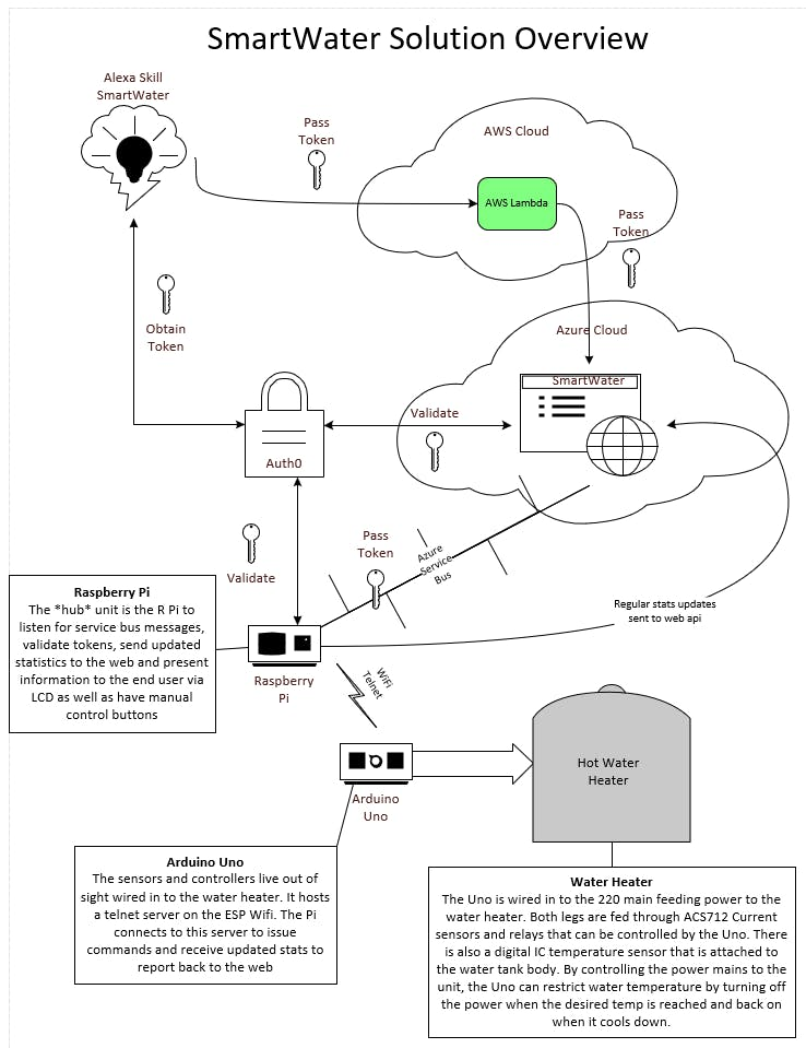 SmartWater Solution Overview
Alexa Skills Kit - Obviously...
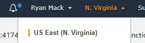
AWS Lambda - Because that's what you do. Note: And I will repeat this... It cost me hours... For the Smart Home Skills you MUST use US East (N. Virginia) region...
Auth0 - I decided on Auth0 for my identity provider. Using their free subscription I can manage all the security for the solution in their friendly portal. If you haven't used them, check em out here!
Azure - I am a little more comfortable in the Azure cloud platform. Nothing against AWS... I am creating the following:
- A restful API that will be the cloud brain for the solution.
- A website for folks to come register their device, setup heating schedules, review power usage and SAVINGS, etc.
- A service bus to provide a durable, secure and zero routing (no port forwarding/router config required) message transport to the IoT counterparts in customers' homes.
Raspberry Pi - I landed on the pi for my on-site application platform. The IoT hub, if you will. The pi will:
- Handle security with the world. Manage the service bus communication and validate tokens with Auth0
- Provide visual system interaction for the user. Since it is wifi, it does not need to live in the utility closet with the water heater. It can go in the hallway next to the HVAC thermostat, or maybe one day even replace that too!
- Proxy the Arduino communication. Allow the Uno to offload high level security concerns to a more robust application platform.
Arduino Uno - The Uno will host the following functional hardware:
- 2 - ACS712 30A current sensors
- 2 - 30A Relays
- 1 - DS18B20 temperature sensor
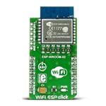
- 1 - ESP-8266 WiFi module (pre-configured)
Building Out the Arduino Uno
ESP-8266 - I had an ESP-8266 already configured for my WiFi to use for this project. I did that using THIS ARTICLE. Following that article I connected the ESP to my Arduino and uploaded the sketch from the article:
void setup()
{
    Serial.begin(9600);
    Serial1.begin(9600);
}
void loop()
{
    while (Serial1.available()) {
        Serial.write(Serial1.read());
    }
   while (Serial.available()) {
        Serial1.write(Serial.read());
    }
}
Once that is working, you can issue AT commands to your ESP from the serial monitor. Here are some notes I made on that:
Full List:
https://github.com/espressif/esp8266_at/wiki
Set baud:
AT+CIOBAUD=9600
Check wifi mode:
AT+CWMODE?
Set Mode to client:
AT+CWMODE=1
List WiFi Nets:
AT+CWLAP
Conect to wireless:
AT+CWJAP="RockChalk","password"
Get IP address:
AT+CIFSR
Allow multiple connections:
AT+CIPMUX=1
Start Server:
AT+CIPSERVER=1,23
Send stuff
AT+CIPSEND=0,11
HELLO WORLD
I used that article for wiring my ESP in this project, too. There are a few notable requirements for operating the ESP with the Uno worth repeating here. The ESP is 3.3v and requires more power than the Uno can deliver. Plan on an external 3.3v supply that can deliver clean power to it. For $25 or so I got one of these and use it all the time with any old DC power supply for projects like this. The other consideration mentioned in the article, the 5v Tx from the Uno will damage the ESP and must be bucked to 3.3v. The CD4050 IC will do that for us.
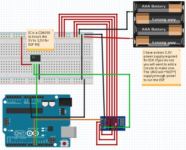
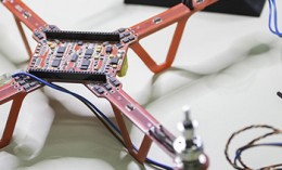
You may note that I have the Rx and Tx wired to the digital pins 10 and 11. This is the *debug* wiring to leave the single serial port on the Uno available for programming and troubleshooting. I am using Arduino's Software Serial library to communicate with the ESP in this configuration.
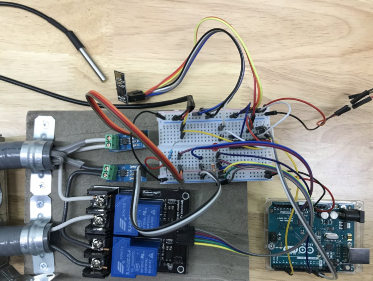
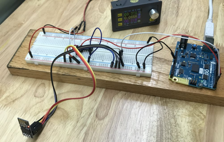 This is the test rig working with the ESP early in the project
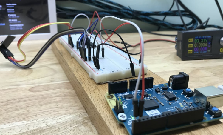 Wired in *release* mode with Tx and Rx connected to hardware serial
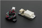
DS18B20 Temperature Sensor - The DS18B20 can be powered by between 3.0V and 5.5V so you can simply connect its GND pin to 0V and the VDD pin to +5V from the Arduino. However, the DS18B20 can also extract its power from the data line which means we only effectively need two wires to connect it up. This makes it great for use as an external sensor.
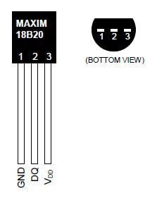 DS18B20 Temperature Sensor
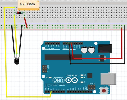 Wiring the DS18B20 temperature sensor
ACS712 Current Sensors and Relays - The 220v service line I will be working with is comprised of two legs of 110v each. That is why I am using two current sensors and relays. The third wire in the 220 line is ground. USE EXTREME CAUTION WHEN WORKING WITH THE 220 VOLT LINES. IT CAN KILL YOU!
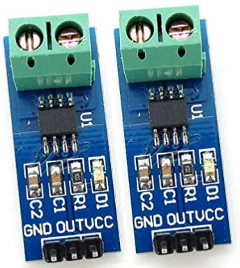 ACS712 Current Sensors
It is a bit tricky to measure AC current with ACS712. There is a fantastic article on the details at i-Snail-VC-50 would be a more professional choice. It's a bit pricey, though.
And finally, the relays. I used a 2 channel RobotDyn 30A/240v relay module
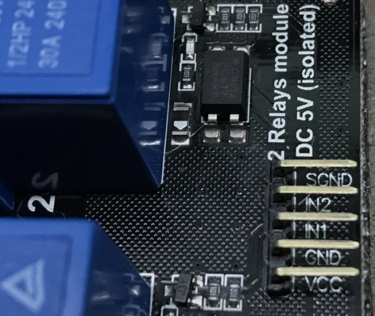 RobotDyn 30A/240v relay module
 Connecting to the AC power. BE CAREFUL!
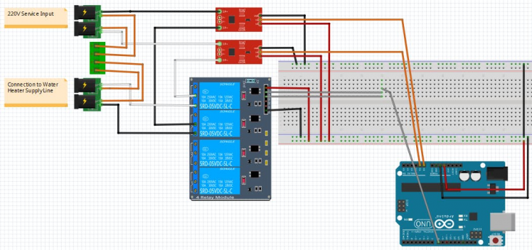
Here is the complete Fritz...
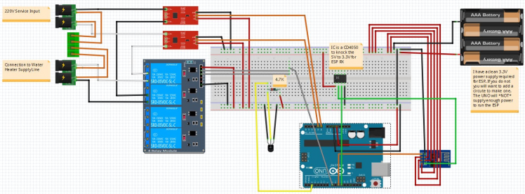 SmartWater Sensor Module Fritzing
 SmartWater Sensor Module
Programming - Setup telnet server on the ESP
I am using the SoftwareSerial library to communicate with the ESP from the Uno. I also have an "IsDebug" variable so I can switch between using the SoftwareSerial and the hardware serial. Let's dig in.
*I will put the code in-line as I document, but the final code available as a whole should be used if you are reproducing this project. In-line code is for general reference.
Right off, I knew that I would need a function to let me know when a command was completed. Here is my function waitFor that can take two strings to watch for, one if it is successful and one if it is not. It watches for the strings coming across the serial port and returns true when it finds the success string and false if it finds the error string. It is also coded to understand whether we are in debug wiring or not.
bool waitFor(String goodResponse, String badResponse){
 bool found = false;
 bool ret = false;
 String buff = "";
 if (IsDebug){
 while (!found){
 if (mySerial.available()) {
                buff += mySerial.readString();
 if (buff.indexOf(goodResponse) >= 0) {
                    found = true;
                    ret = true;
                }
 if (buff.indexOf(badResponse) >= 0) {
                    found = true;
                    ret = false;
                }
 const char * msgBuff = buff.c_str();
                Serial.write(msgBuff);
            }
        }
    }
 else {
 while (!found){
 if (Serial.available()) {
                buff += Serial.readString();
 if (buff.indexOf(goodResponse) >= 0) {
                    found = true;
                    ret = true;
                }
 if (buff.indexOf(badResponse) >= 0) {
                    found = true;
                    ret = false;
                }
            }
        }
    }
 return ret;
}
Okay, good. Next we need to initialize our ESP to set it up as a server to listen for incoming connections.
void initServerDebug(){
 digitalWrite(LED_BUILTIN, LOW);
 // start serial port
    Serial.begin(9600);
 while (!Serial) {
        ; // wait for serial port to connect. Needed for native USB port only
    }
 // set the data rate for the SoftwareSerial port
    mySerial.begin(115200);
    mySerial.println("AT+CIOBAUD=9600");
 delay(2000);
    mySerial.end();
    mySerial.begin(9600);
 //Enable multiple connections
    mySerial.println("AT+CIPMUX=1");
 waitFor("OK", "ERROR");
 //Start the server
    mySerial.println("AT+CIPSERVER=1,23");
 waitFor("OK", "ERROR");
 digitalWrite(LED_BUILTIN, HIGH);
}
void initServer(){
 digitalWrite(LED_BUILTIN, LOW);
 // set the data rate for the SoftwareSerial port
    Serial.begin(115200);
    Serial.println("AT+CIOBAUD=9600");
 delay(2000);
    Serial.end();
    Serial.begin(9600);
 //Enable multiple connections
    Serial.println("AT+CIPMUX=1");
 waitFor("OK", "ERROR");
 //Start the server
    Serial.println("AT+CIPSERVER=1,23");
 waitFor("OK", "ERROR");
 digitalWrite(LED_BUILTIN, HIGH);
}
Once a connection is established we need to listen for incoming commands and respond appropriately. I packaged that up in a function handleComm that will be called from the main loop.
void handleComm(){
 bool avail = IsDebug ? mySerial.available() : Serial.available();
    String cmd;
 if (!avail) return;
    cmd = IsDebug ? mySerial.readString() : Serial.readString();
 int start = cmd.indexOf(":GO");
 if (start >= 0){
 sendMsg(buildReport());
 if (IsDebug) Serial.write("REPORT SENT");
    }
    start = cmd.indexOf(":SET");
 if (start >= 0){
        String newTemp = cmd.substring(start+5,start+8);
        TargetTemp = newTemp.toDouble();
        LowerLimit = TargetTemp - 1;
 sendMsg(buildReport());
 if (IsDebug) Serial.write("TEMP SET");
    }
    start = cmd.indexOf(":ZERO");
 if (start >= 0){
        LastTempTicks = 0;
        LastWattsTicks = 0;
        WattMinutes = 0;
        MinutesTracked = -1;
        ThisMinuteWatts = 0;
        ThisMinuteMinutes = 0;
        InWattMinute = false;
 sendMsg(buildReport());
 if (IsDebug) Serial.write("RESET STATS");
    }
}
Finally, a function to send messages back to the connected peer.
void sendMsg(String message){
    String cmd = "AT+CIPSEND=0,";
    cmd += message.length();
    cmd += "rn";
 const char * cmdBuff = cmd.c_str();
 const char * msgBuff = message.c_str();
 if (IsDebug){
        mySerial.write(cmdBuff);
 waitFor("OK", "ERROR");
        mySerial.write(msgBuff);
    } else{
        Serial.write(cmdBuff);
 waitFor("OK", "ERROR");
        Serial.write(msgBuff);
    }
}
Here is the complete sketch for the communications portion of the application
#include <Arduino.h>
#include <SoftwareSerial.h>
const int legOneIn = A0;
const int legTwoIn = A1;
int mVperAmp = 66; // use 66 for 30A, use 100 for 20A Module and 185 for 5A Module
int ACSoffset = 2500;
double LegOneAmps = 0;
double LegTwoAmps = 0;
double WattMinutes = 0;
int MinutesTracked = -1;
double ThisMinuteWatts = 0;
double ThisMinuteMinutes = 0;
bool InWattMinute = false;
//Our variables
double CurrentTemp = 0; //Default to turn it on!
double TargetTemp = 150; //Water heater max (default to water heater setting)
double LowerLimit = 145; //Water shoudl maintain between lower limit and target. When lower limit is reached, it will turn on.
bool PowerOn = false; //Turn on relay's in setup
//Misc
unsigned long LastTempTicks = 0;
unsigned long LastWattsTicks = 0;
//For debugging we use pins 10 and 11 instead of the serial port
bool IsDebug = true;
SoftwareSerial mySerial(10, 11); // RX, TX
//methods
void initServerDebug();
void handleComm();
void initServer();
bool waitFor(String goodResponse, String badResponse);
void doTemperature(void);
void doPower(void);
void setRelay(bool turnOn);
void sendMsg(String message);
String buildReport();
void setup(void)
{
 if (IsDebug)
 initServerDebug();
 else
 initServer();
}
void loop(void)
{
 handleComm();
}
void handleComm(){
 bool avail = IsDebug ? mySerial.available() : Serial.available();
    String cmd;
 if (!avail) return;
    cmd = IsDebug ? mySerial.readString() : Serial.readString();
 int start = cmd.indexOf(":GO");
 if (start >= 0){
 sendMsg(buildReport());
 if (IsDebug) Serial.write("REPORT SENT");
    }
    start = cmd.indexOf(":SET");
 if (start >= 0){
        String newTemp = cmd.substring(start+5,start+8);
        TargetTemp = newTemp.toDouble();
        LowerLimit = TargetTemp - 1;
 sendMsg(buildReport());
 if (IsDebug) Serial.write("TEMP SET");
    }
    start = cmd.indexOf(":ZERO");
 if (start >= 0){
        LastTempTicks = 0;
        LastWattsTicks = 0;
        WattMinutes = 0;
        MinutesTracked = -1;
        ThisMinuteWatts = 0;
        ThisMinuteMinutes = 0;
        InWattMinute = false;
 sendMsg(buildReport());
 if (IsDebug) Serial.write("RESET STATS");
    }
}
void sendMsg(String message){
    String cmd = "AT+CIPSEND=0,";
    cmd += message.length();
    cmd += "rn";
 const char * cmdBuff = cmd.c_str();
 const char * msgBuff = message.c_str();
 if (IsDebug){
        mySerial.write(cmdBuff);
 waitFor("OK", "ERROR");
        mySerial.write(msgBuff);
    } else{
        Serial.write(cmdBuff);
 waitFor("OK", "ERROR");
        Serial.write(msgBuff);
    }
}
bool waitFor(String goodResponse, String badResponse){
 bool found = false;
 bool ret = false;
    String buff = "";
 if (IsDebug){
 while (!found){
 if (mySerial.available()) {
                buff += mySerial.readString();
 if (buff.indexOf(goodResponse) >= 0) {
                    found = true;
                    ret = true;
                }
 if (buff.indexOf(badResponse) >= 0) {
                    found = true;
                    ret = false;
                }
 const char * msgBuff = buff.c_str();
                Serial.write(msgBuff);
            }
        }
    }
 else {
 while (!found){
 if (Serial.available()) {
                buff += Serial.readString();
 if (buff.indexOf(goodResponse) >= 0) {
                    found = true;
                    ret = true;
                }
 if (buff.indexOf(badResponse) >= 0) {
                    found = true;
                    ret = false;
                }
            }
        }
    }
 return ret;
}
void initServerDebug(){
 digitalWrite(LED_BUILTIN, LOW);
 // start serial port
    Serial.begin(9600);
 while (!Serial) {
        ; // wait for serial port to connect. Needed for native USB port only
    }
    Serial.println("Dallas Temperature IC Control Library Demo");
 // set the data rate for the SoftwareSerial port
    mySerial.begin(115200);
    mySerial.println("AT+CIOBAUD=9600");
 delay(2000);
    mySerial.end();
    mySerial.begin(9600);
    mySerial.println("AT+CIPMUX=1");
 waitFor("OK", "ERROR");
    mySerial.println("AT+CIPSERVER=1,23");
 waitFor("OK", "ERROR");
 digitalWrite(LED_BUILTIN, HIGH);
}
void initServer(){
 digitalWrite(LED_BUILTIN, LOW);
 // set the data rate for the SoftwareSerial port
    Serial.begin(115200);
    Serial.println("AT+CIOBAUD=9600");
 delay(2000);
    Serial.end();
    Serial.begin(9600);
    Serial.println("AT+CIPMUX=1");
 waitFor("OK", "ERROR");
    Serial.println("AT+CIPSERVER=1,23");
 waitFor("OK", "ERROR");
 digitalWrite(LED_BUILTIN, HIGH);
}
String buildReport(){
    String ret = "{"Current": ";
    ret += CurrentTemp;
    ret += ", "Target": ";
    ret += TargetTemp;
    ret += ", "Lower": ";
    ret += LowerLimit;
    ret += ", "TrackedMinutes": ";
    ret += MinutesTracked;
    ret += ", "Leg1Amps": ";
    ret += LegOneAmps;
    ret += ", "WattMinutes": ";
    ret += WattMinutes;
    ret += ", "Leg2Amps": ";
    ret += LegTwoAmps;
    ret += "}";
 return ret;
}
Programming - Monitoring the temperature
I am using the OneWire library and the DallasTemperature library built for the DS18B20 temperature sensor available HERE ON GITHUB. With those libraries it is very straight forward to take the temperature reading. I packaged that up on a doTemperature function and call that every 30 seconds form the main loop
#include <Arduino.h>
#include <OneWire.h>
#include <DallasTemperature.h>
// Data wire is plugged into pin 2 on the Arduino
#define ONE_WIRE_BUS 2
// Setup a oneWire instance to communicate with any OneWire devices
// (not just Maxim/Dallas temperature ICs)
OneWire oneWire(ONE_WIRE_BUS);
// Pass our oneWire reference to Dallas Temperature.
DallasTemperature sensors(&oneWire);
const int legOneIn = A0;
const int legTwoIn = A1;
int mVperAmp = 66; // use 66 for 30A, use 100 for 20A Module and 185 for 5A Module
int ACSoffset = 2500;
double LegOneAmps = 0;
double LegTwoAmps = 0;
double WattMinutes = 0;
int MinutesTracked = -1;
double ThisMinuteWatts = 0;
double ThisMinuteMinutes = 0;
bool InWattMinute = false;
//Relays
const int RelaysOut = 8;
//Our variables
double CurrentTemp = 0; //Default to turn it on!
double TargetTemp = 150; //Water heater max (default to water heater setting)
double LowerLimit = 145; //Water shoudl maintain between lower limit and target. When lower limit is reached, it will turn on.
bool PowerOn = false; //Turn on relay's in setup
//Misc
unsigned long LastTempTicks = 0;
unsigned long LastWattsTicks = 0;
//For debugging we use pins 10 and 11 instead of the serial port
bool IsDebug = true;
//methods
void doTemperature(void);
void setup(void)
{
 //setup pins
 pinMode(LED_BUILTIN, OUTPUT);
 // Start up the library
    sensors.begin();
}
void loop(void)
{
 //Take temp every 30 seconds
 if (millis() >= LastTempTicks + 30000){
 doTemperature();
        LastTempTicks = millis();
    }
}
void doTemperature(void){
 // call sensors.requestTemperatures() to issue a global temperature
 // request to all devices on the bus
    sensors.requestTemperatures(); // Send the command to get temperatures
    CurrentTemp = sensors.getTempFByIndex(0);// Why "byIndex"?
 // You can have more than one IC on the same bus.
 // 0 refers to the first IC on the wire
 if (CurrentTemp < LowerLimit && !PowerOn){
 setRelay(true);
    }
 if (CurrentTemp >= TargetTemp && PowerOn){
 setRelay(false);
    }
}
Programming - Controlling the Relays
Well, not much to that. Here is the setRelay function for that. RelaysOut is the pin we are connecting to them.
void setRelay(bool turnOn){
 if (turnOn) {
 digitalWrite(RelaysOut, HIGH);
        PowerOn = true;
    }
 else {
 digitalWrite(RelaysOut, LOW);
        PowerOn = false;
    }
}
Programming - Reading current from the ACS712
As mentioned earlier, reading AC current on the ACS712 is a little sketchy, but should be fine for proof of concept work. Here is the function to get the raw voltage slightly modified from the Henry's Bench article:
float getVPP(int sensorPin)
{
 float result;
 int readValue;             //value read from the sensor
 int maxValue = 0;          // store max value here
 int minValue = 1024;          // store min value here
 uint32_t start_time = millis();
 while((millis()-start_time) < 1000) //sample for 1 Sec
    {
        readValue = analogRead(sensorPin);
 // see if you have a new maxValue
 if (readValue > maxValue)
        {
 /*record the maximum sensor value*/
            maxValue = readValue;
        }
 if (readValue < minValue)
        {
 /*record the maximum sensor value*/
            minValue = readValue;
        }
    }
 // Subtract min from max
    result = ((maxValue - minValue) * 5.0)/1024.0;
 return result;
}
This function reads the voltages returned from the ACS for 1 second and uses the max and min values to produce the voltage measurement used in the following to determine the RMS amps, then calculate watts and then store that over time to accumulate watt/minutes for later conversion in to kilowatt-hours to estimate cost and savings:
void doPower(void){
 double legOneVoltage;
 double legTwoVoltage;
 double legOneVoltageRMS;
 double legTwoVoltageRMS;
 double minutes;
 int watts;
 if (PowerOn){
        legOneVoltage = getVPP(legOneIn);
        legOneVoltageRMS = (legOneVoltage/2.0) *0.707;
        LegOneAmps = ((legOneVoltageRMS * 1000) / mVperAmp);
        legTwoVoltage = getVPP(legTwoIn);
        legTwoVoltageRMS = (legTwoVoltage/2.0) *0.707;
        LegTwoAmps = ((legTwoVoltageRMS * 1000) / mVperAmp);
        minutes = (millis() - LastWattsTicks) / 60000.0;
        LastWattsTicks = millis();
 //Watts = Amps * Volts
        watts = (LegOneAmps * 120) + (LegTwoAmps * 120);
    } else{
        LegOneAmps = 0;
        LegTwoAmps = 0;
        minutes = (millis() - LastWattsTicks) / 60000.0;
        LastWattsTicks = millis();
        watts = 0;
    }
if (InWattMinute){
        ThisMinuteMinutes += minutes;
        ThisMinuteWatts += watts * minutes;
 if (ThisMinuteMinutes >= 1)
            InWattMinute = false;
    } else{
        WattMinutes += ThisMinuteWatts;
        MinutesTracked++;
        InWattMinute = true;
        ThisMinuteMinutes = minutes;
        ThisMinuteWatts = watts * minutes;
    }
}
Finally, in the main loop I am calling this every 10 seconds. That time-frame may need tweaking, though.
void loop(void)
{
 //sample power every 10 seconds
 if (millis() >= LastWattsTicks + 10000){
 doPower();
    }
}
Programming - Complete sketch for the Arduino Uno
*Also available as a download
#include <Arduino.h>
#include <OneWire.h>
#include <DallasTemperature.h>
#include <SoftwareSerial.h>
// Data wire is plugged into pin 2 on the Arduino
#define ONE_WIRE_BUS 2
// Setup a oneWire instance to communicate with any OneWire devices
// (not just Maxim/Dallas temperature ICs)
OneWire oneWire(ONE_WIRE_BUS);
// Pass our oneWire reference to Dallas Temperature.
DallasTemperature sensors(&oneWire);
 /*
Measuring Current Using ACS712
*/
const int legOneIn = A0;
const int legTwoIn = A1;
int mVperAmp = 66; // use 66 for 30A, use 100 for 20A Module and 185 for 5A Module
int ACSoffset = 2500;
double LegOneAmps = 0;
double LegTwoAmps = 0;
double WattMinutes = 0;
int MinutesTracked = -1;
double ThisMinuteWatts = 0;
double ThisMinuteMinutes = 0;
bool InWattMinute = false;
//Relays
const int RelaysOut = 8;
//Our variables
double CurrentTemp = 0; //Default to turn it on!
double TargetTemp = 150; //Water heater max (default to water heater setting)
double LowerLimit = 145; //Water shoudl maintain between lower limit and target. When lower limit is reached, it will turn on.
bool PowerOn = false; //Turn on relay's in setup
//Misc
unsigned long LastTempTicks = 0;
unsigned long LastWattsTicks = 0;
//For debugging we use pins 10 and 11 instead of the serial port
bool IsDebug = true;
SoftwareSerial mySerial(10, 11); // RX, TX
//methods
void initServerDebug();
void handleComm();
void initServer();
bool waitFor(String goodResponse, String badResponse);
void doTemperature(void);
float getVPP(int sensorPin);
void doPower(void);
void setRelay(bool turnOn);
void sendMsg(String message);
String buildReport();
void setup(void)
{
 //setup pins
 pinMode(RelaysOut, OUTPUT);
 pinMode(LED_BUILTIN, OUTPUT);
 //init relay's to off
 setRelay(false);
 // Start up the library
    sensors.begin();
 if (IsDebug)
 initServerDebug();
 else
 initServer();
}
void loop(void)
{
 //sample power every 10 seconds
 if (millis() >= LastWattsTicks + 10000){
 doPower();
    }
}
void handleComm(){
 bool avail = IsDebug ? mySerial.available() : Serial.available();
    String cmd;
 if (!avail) return;
    cmd = IsDebug ? mySerial.readString() : Serial.readString();
 int start = cmd.indexOf(":GO");
 if (start >= 0){
 sendMsg(buildReport());
 if (IsDebug) Serial.write("REPORT SENT");
    }
    start = cmd.indexOf(":SET");
 if (start >= 0){
        String newTemp = cmd.substring(start+5,start+8);
        TargetTemp = newTemp.toDouble();
        LowerLimit = TargetTemp - 1;
 sendMsg(buildReport());
 if (IsDebug) Serial.write("TEMP SET");
    }
    start = cmd.indexOf(":ZERO");
 if (start >= 0){
        LastTempTicks = 0;
        LastWattsTicks = 0;
        WattMinutes = 0;
        MinutesTracked = -1;
        ThisMinuteWatts = 0;
        ThisMinuteMinutes = 0;
        InWattMinute = false;
 sendMsg(buildReport());
 if (IsDebug) Serial.write("RESET STATS");
    }
}
void sendMsg(String message){
    String cmd = "AT+CIPSEND=0,";
    cmd += message.length();
    cmd += "rn";
 const char * cmdBuff = cmd.c_str();
 const char * msgBuff = message.c_str();
 if (IsDebug){
        mySerial.write(cmdBuff);
 waitFor("OK", "ERROR");
        mySerial.write(msgBuff);
    } else{
        Serial.write(cmdBuff);
 waitFor("OK", "ERROR");
        Serial.write(msgBuff);
    }
}
bool waitFor(String goodResponse, String badResponse){
 bool found = false;
 bool ret = false;
    String buff = "";
 if (IsDebug){
 while (!found){
 if (mySerial.available()) {
                buff += mySerial.readString();
 if (buff.indexOf(goodResponse) >= 0) {
                    found = true;
                    ret = true;
                }
 if (buff.indexOf(badResponse) >= 0) {
                    found = true;
                    ret = false;
                }
 const char * msgBuff = buff.c_str();
                Serial.write(msgBuff);
            }
        }
    }
 else {
 while (!found){
 if (Serial.available()) {
                buff += Serial.readString();
 if (buff.indexOf(goodResponse) >= 0) {
                    found = true;
                    ret = true;
                }
 if (buff.indexOf(badResponse) >= 0) {
                    found = true;
                    ret = false;
                }
            }
        }
    }
 return ret;
}
void doTemperature(void){
 // call sensors.requestTemperatures() to issue a global temperature
 // request to all devices on the bus
    sensors.requestTemperatures(); // Send the command to get temperatures
    CurrentTemp = sensors.getTempFByIndex(0);// Why "byIndex"?
 // You can have more than one IC on the same bus.
 // 0 refers to the first IC on the wire
 if (CurrentTemp < LowerLimit && !PowerOn){
 setRelay(true);
    }
 if (CurrentTemp >= TargetTemp && PowerOn){
 setRelay(false);
    }
}
void doPower(void){
 double legOneVoltage;
 double legTwoVoltage;
 double legOneVoltageRMS;
 double legTwoVoltageRMS;
 double minutes;
 int watts;
 if (PowerOn){
        legOneVoltage = getVPP(legOneIn);
        legOneVoltageRMS = (legOneVoltage/2.0) *0.707;
        LegOneAmps = ((legOneVoltageRMS * 1000) / mVperAmp);
        legTwoVoltage = getVPP(legTwoIn);
        legTwoVoltageRMS = (legTwoVoltage/2.0) *0.707;
        LegTwoAmps = ((legTwoVoltageRMS * 1000) / mVperAmp);
        minutes = (millis() - LastWattsTicks) / 60000.0;
        LastWattsTicks = millis();
 //Watts = Amps * Volts
        watts = (LegOneAmps * 120) + (LegTwoAmps * 120);
    } else{
        LegOneAmps = 0;
        LegTwoAmps = 0;
        minutes = (millis() - LastWattsTicks) / 60000.0;
        LastWattsTicks = millis();
        watts = 0;
    }
if (InWattMinute){
        ThisMinuteMinutes += minutes;
        ThisMinuteWatts += watts * minutes;
 if (ThisMinuteMinutes >= 1)
            InWattMinute = false;
    } else{
        WattMinutes += ThisMinuteWatts;
        MinutesTracked++;
        InWattMinute = true;
        ThisMinuteMinutes = minutes;
        ThisMinuteWatts = watts * minutes;
    }
}
float getVPP(int sensorPin)
{
 float result;
 int readValue;             //value read from the sensor
 int maxValue = 0;          // store max value here
 int minValue = 1024;          // store min value here
 uint32_t start_time = millis();
 while((millis()-start_time) < 1000) //sample for 1 Sec
    {
        readValue = analogRead(sensorPin);
 // see if you have a new maxValue
 if (readValue > maxValue)
        {
 /*record the maximum sensor value*/
            maxValue = readValue;
        }
 if (readValue < minValue)
        {
 /*record the maximum sensor value*/
            minValue = readValue;
        }
    }
 // Subtract min from max
    result = ((maxValue - minValue) * 5.0)/1024.0;
 return result;
}
void setRelay(bool turnOn){
 if (turnOn) {
 digitalWrite(RelaysOut, HIGH);
        PowerOn = true;
    }
 else {
 digitalWrite(RelaysOut, LOW);
        PowerOn = false;
    }
}
void initServerDebug(){
 digitalWrite(LED_BUILTIN, LOW);
 // start serial port
    Serial.begin(9600);
 while (!Serial) {
        ; // wait for serial port to connect. Needed for native USB port only
    }
    Serial.println("Dallas Temperature IC Control Library Demo");
 // set the data rate for the SoftwareSerial port
    mySerial.begin(115200);
    mySerial.println("AT+CIOBAUD=9600");
 delay(2000);
    mySerial.end();
    mySerial.begin(9600);
    mySerial.println("AT+CIPMUX=1");
 waitFor("OK", "ERROR");
    mySerial.println("AT+CIPSERVER=1,23");
 waitFor("OK", "ERROR");
 digitalWrite(LED_BUILTIN, HIGH);
}
void initServer(){
 digitalWrite(LED_BUILTIN, LOW);
 // set the data rate for the SoftwareSerial port
    Serial.begin(115200);
    Serial.println("AT+CIOBAUD=9600");
 delay(2000);
    Serial.end();
    Serial.begin(9600);
    Serial.println("AT+CIPMUX=1");
 waitFor("OK", "ERROR");
    Serial.println("AT+CIPSERVER=1,23");
 waitFor("OK", "ERROR");
 digitalWrite(LED_BUILTIN, HIGH);
}
String buildReport(){
    String ret = "{"Current": ";
    ret += CurrentTemp;
    ret += ", "Target": ";
    ret += TargetTemp;
    ret += ", "Lower": ";
    ret += LowerLimit;
    ret += ", "TrackedMinutes": ";
    ret += MinutesTracked;
    ret += ", "Leg1Amps": ";
    ret += LegOneAmps;
    ret += ", "WattMinutes": ";
    ret += WattMinutes;
    ret += ", "Leg2Amps": ";
    ret += LegTwoAmps;
    ret += "}";
 return ret;
}
Building out the Raspberry Pi
I am using the pi to create an interface device that does not have to live in the utility closet mounted to the water heater. I am also leveraging the pi as the application platform. The pi is the hub device that will connect the the Arduino smart water sensor controller to the cloud. As such, there is not a lot of hardware on the pi. Currently there is simply a 4 line LCD display connected. This will be expanded to house some controls to manually manipulate the system much like you would your HVAC thermostat. These controls could also be used to complete the initial setup in a production system. Connect to the local WiFi and stuff. But I digress.
For the operating system I am using Windows 10 IoT Core and did all my programming in Visual Studio using C#.
For the LCD I am using a SunFounder I2C 2004 20x4 LCD. and wired it to the pi as follows:
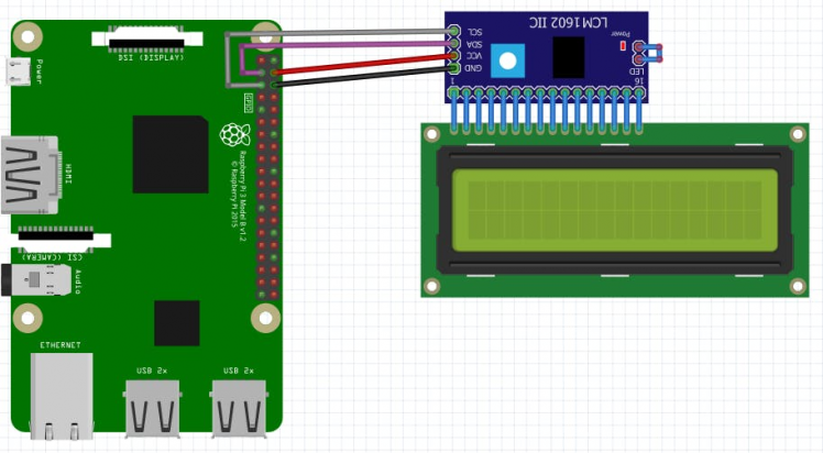 I2C LCM1602 and LCD wired to Raspberry Pi
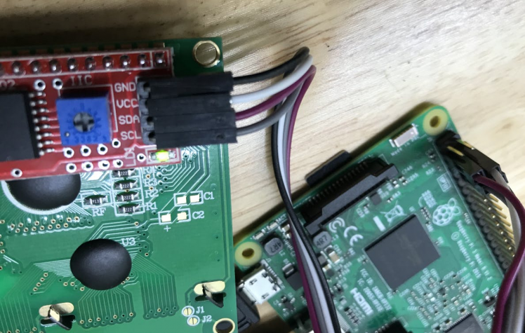 Actual wiring
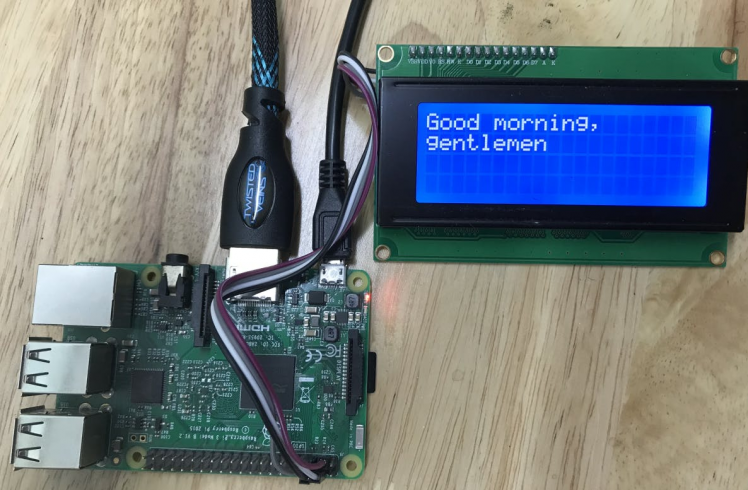 Display Operational!
I2C LCD Display Library
More to come on the programming for the pi, however, to give some credit here, I found a great launching point for my I2C LCD communication library here. You will notice that I have only slightly modified displayI2C.cs to suit my needs.
Create New Alexa Smart Home Skill
First thing you will want to do is configure your new Smart Home skill.
If you do not already have a free developer account for Amazon, go HERE and do that first.
Once logged into the developer console, go to Alexa and select get started on the Alexa Skills Kit
 Get Started with Alexa Skills Kit
We will, of course, be "Adding a New Skill"
 Click "Add a New Skill"
For this skill, I am creating a "Smart Home Skill" configured like so
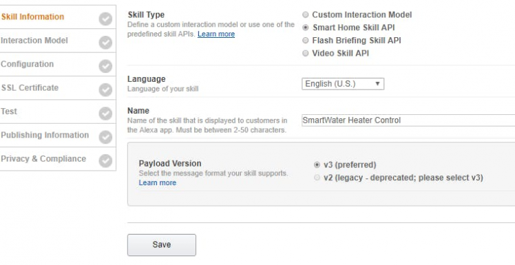 Name your Smart Home skill
On the next page, make note of your Application Id. You will need this later
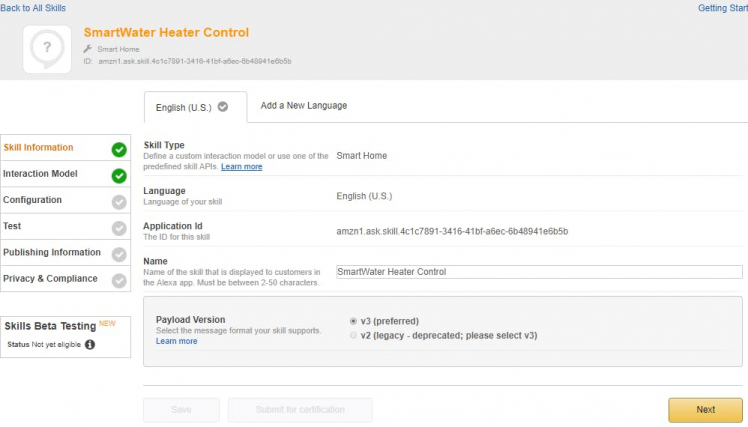 Note your application id both in the header and in the dialog
You do not need to define your interaction model with a Smart Home skill. It is predefined by the Alexa team.
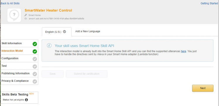 No Interaction Model with Smart Home Skill
On the next step, we just want to note the Redirect URL's.
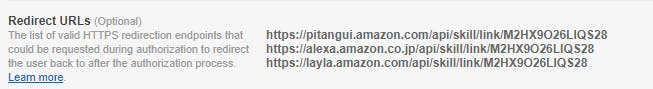 Note the Redirect URL's
That's it for now. We will come back here and continue with this configuration once we have created the Lambda function and AuthO client.
Create Lambda in AWS
After creating your skill you can create a Lambda in AWS that your skill will interact with. My Lambda function pretty much just relays the calls from the Amazon skill to my API. Handling the business logic, security and application functionality in the API allows me to reuse that in the web portal down the road.
If you do not have a free developer account for AWS, do that first here.
Once in the console, immediately switch your region to US East (N. Virginia). This is the only region that supports Alexa Smart Home Skills
 Select US East region
Now search for Lambda in the search box
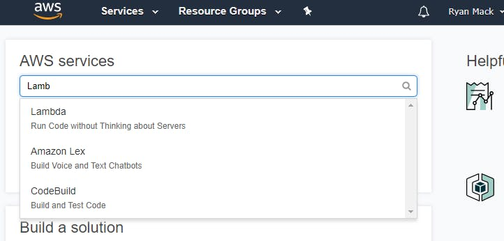 Search for the Lambda dashboard
Once there, verify you are still in the N. Virginia region and click Create Function
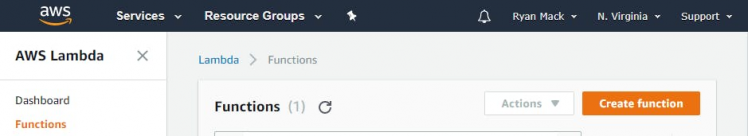 Create Function
Select Blueprints and add "Alexa" keyword. You should see "alexa-smart-home-skill-adapter" as an option
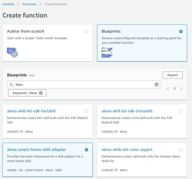 Use the Alexa smart home blueprint
When filling in the Basic Information, I selected "Create new role from template" and simply used the "Simple Microservice permissions" template.
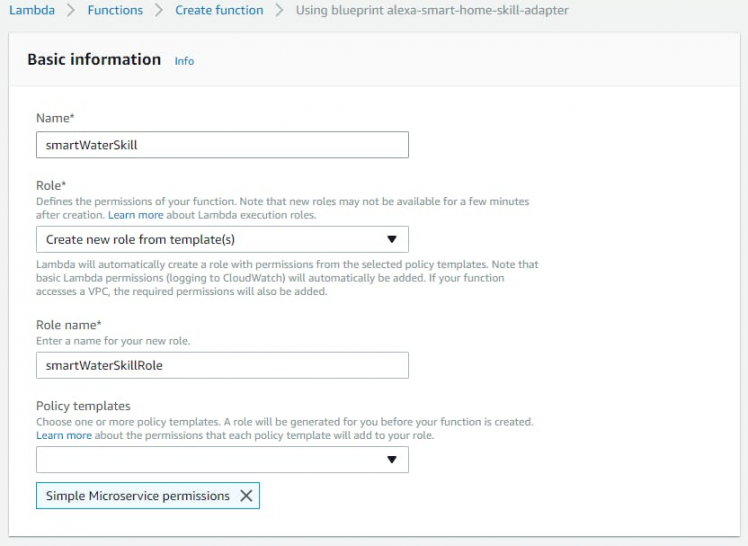 Name your function and create a role
In the next block you will need your Application Id from your Alexa skill
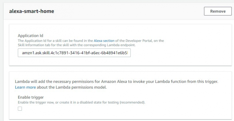 Enter your Alexa Skill Application Id
This should be enough to create your function. You should end up on your function dashboard that looks something like this
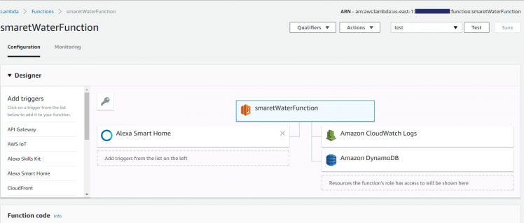 Lambda Function Dashboard
Make a note of the ARN in the upper right hand corner. You will need to plug that back in to the Skill configuration when you get back to that.
Create Web App in Azure
I have chosen to host my API in Azure.
If you do not already have a free Azure developer account, go HERE and set one up.
So the first thing to do is setup your application space. In Azure click "App Services" and then Add
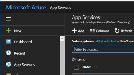 Click "Add"
Select "Web App" and click "Create"
 Select Web App
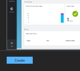 Click Create
This is where you will brand your URL. In the image I am using smartwater2 since I already have smartwater taken
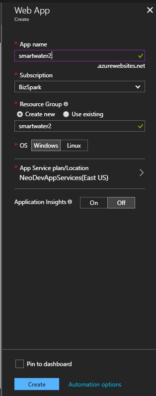 Give you app a name
That's it! You now have an environment ready to deploy your api when you are ready and you have reserved a URL for it as well.
Configuring Auth0 for Alexa Skills OAuth
Now lets configure our authentication in Auth0.
If you do not have a free Auth0 account, get one HERE.
***** PLEASE NOTE **** If you go through the new user tutorial it will have you create a login rule. PLEASE DELETE THIS RULE AFTER THE TUTORIAL. It will cause you much pain and suffering when you get around to creating your first client if you do not delete that rule immediately after you are done with it.
Okay, first thing you will want to do is define your API.
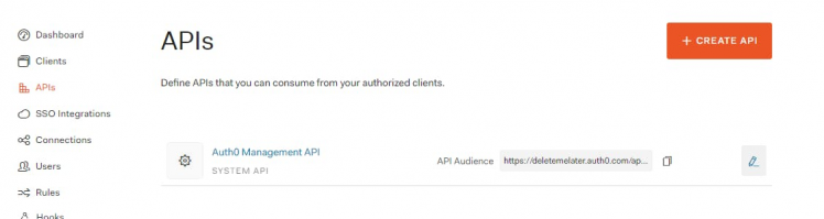 Click "Create API"
You will need your URL from your Azure setup here:
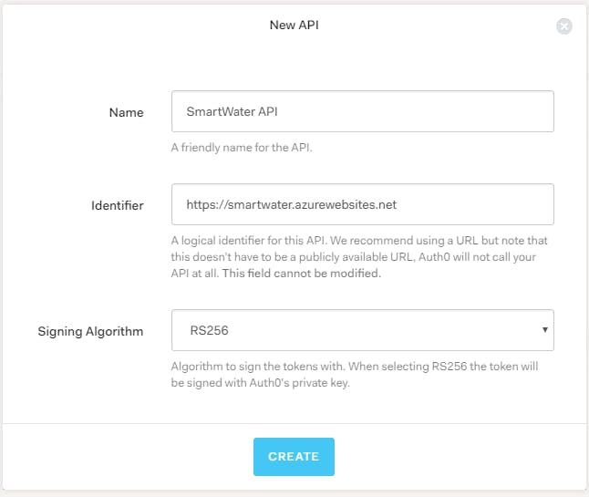 Give it a name and Enter URL for your Azure Web App
Once that is created, the only setting that needs to be adjusted is the "Allow Offline Access". You will want to flip that to yes on the "Settings" tab
 Alexa Skill will be requesting Refresh Tokens
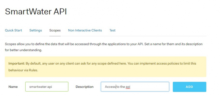
On the "Scopes" tab, add a scope that we can use in the API to authorize the access
Next, create your client:
 Click "Create Client"
There will not be a user interface so we will select "non-interactive" for this client
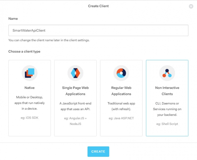 Name in and select "Non Interactive"
Select the API you created and use the helper to authorize it
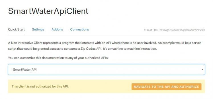 Navigate and Authorize
On that page, Authorize the client and include the Scope we created earlier by checking that box
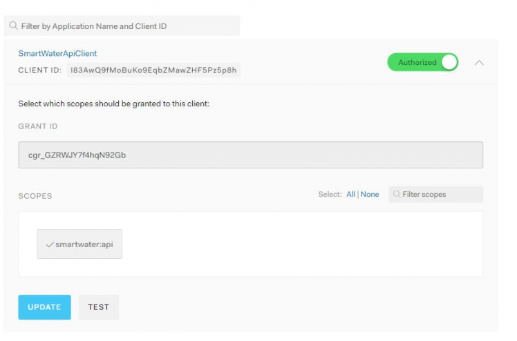 Authorize client and include custom scope
Back in the Settings tab on the Client setup you will want to enter your endpoints from the Alexa skill "Redirect URLs" in the "Allowed Callback URLs"
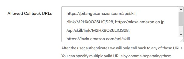 Copy URL's from Alexa skill
There is also some pertinent information here that needs to be copied back tot hat skill. You will want to grab the Client Id and secret
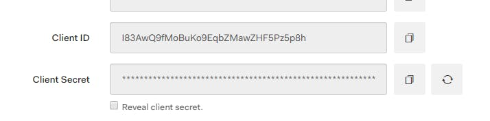 Copy your client Id and secret for Account Linking in your Skill
That's it for Auth0 for now. To finalize the cloud configurations, take the additional information we have generated for the skill and apply it back to the Skill configuration.
Finalizing Alexa Skill Configuration
Apply your ARN from your Lambda function
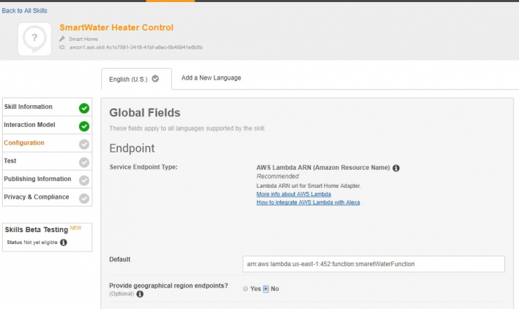 Copy in your AWS Lambda ARN
Apply your Auth0 settings to the Account Linking configuration block
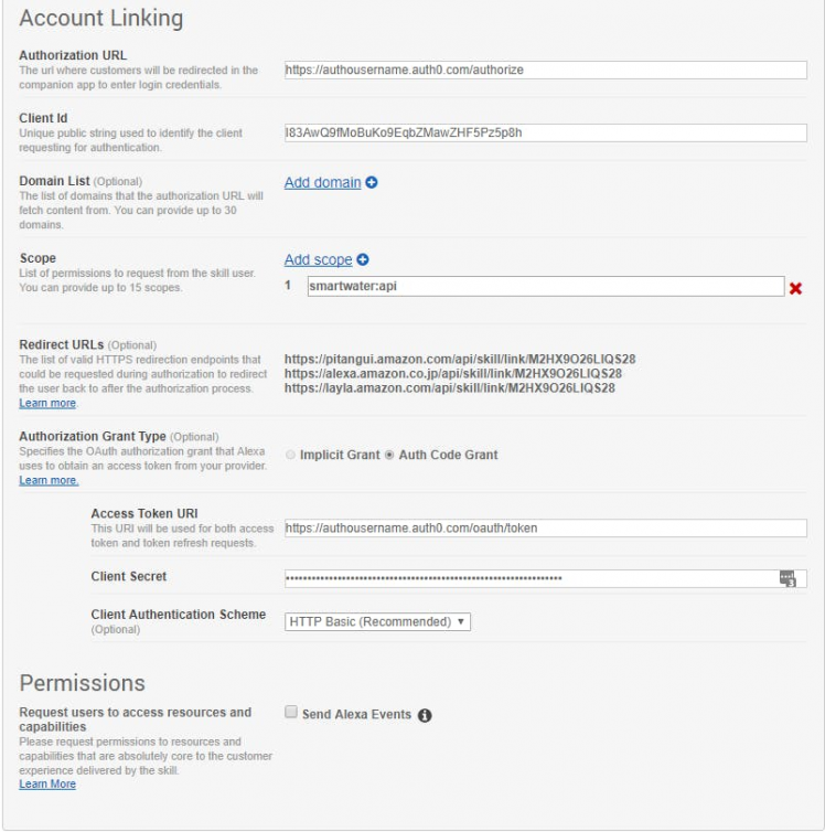 Copy settings from Auth0
That should do it! We now have Alexa Smart Home skill configured with an AWS Lambda function to authenticate and authorize users leveraging Auth0. We also have configured an Azure web app to host our API we will be creating in the following sections.
Create Azure Service Bus
The last bit of infrastructure we need to setup is the service bus. The service bus will provide a robust, durable communication link from the cloud to our internal bits. It also eliminates the need for any network configuration to shuttle communications in from the web.
In the Azure portal, simply create a new Service Bus.
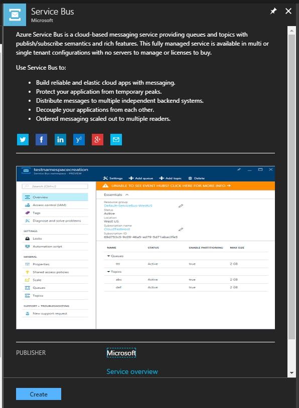 Create a new Service Bus
Be sure to change the pricing plan to Basic from the default of Standard.
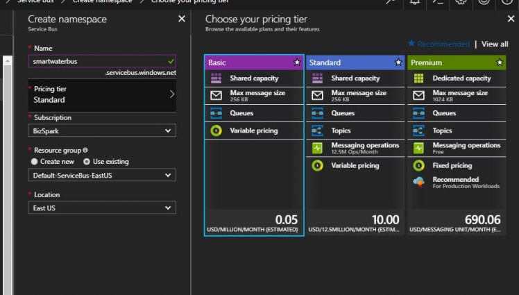 Select Basic Pricing Plan
Setup the Programming Environment
For everything but the Arduino, I am using Visual Studio 2017. You will need the AWS Toolkit for Visual Studio extension. This will allow you to create and deploy Lambda Functions using C# and Visual Studio.
For the Arduino I am using Visual Studio Code with Platform IO installed.
Create the Lambda Function
The AWS Toolkit will install the Lambda templates for you. To create your C# Lambda simple add a new project and find the AWS Lambda Project in your Visual C# project templates under AWS Lambda
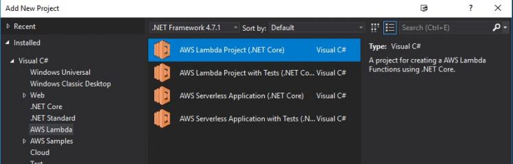 Create a new AWS Lambda Project
I decided to make my Lambda function pretty minimal and do most of the lifting in the API. Since the goal is to have a nice web platform that users can log in to and manage their water heater, I thought that would maximize my re-usability.
You can see in the FunctionHandler below, I am determining what commend we are receiving and taking the token out of the input. Using the token, I format an authentication header for my API and post the command name and input on for processing.
public dynamic FunctionHandler(dynamic input, ILambdaContext context)
{
   // check what type of a request it is like an IntentRequest or a LaunchRequest
   log("input", JsonConvert.SerializeObject(input));
   log("context", JsonConvert.SerializeObject(context));
   HttpResponseMessage resp;
   var clt = new HttpClient();
   string token = "";
   string command = input.directive.header.name;
   switch (command.ToLower())
   {
       case "discover":
           token = input.directive.payload.scope.token;
           break;
       case "reportstate":
           token = input.directive.endpoint.scope.token;
           break;
   }
   clt.BaseAddress = new Uri("https://smartwater.azurewebsites.net");
   clt.DefaultRequestHeaders.Accept.Clear();
   clt.DefaultRequestHeaders.Accept.Add(new MediaTypeWithQualityHeaderValue("application/json"));
   clt.DefaultRequestHeaders.Authorization =
       new AuthenticationHeaderValue("Bearer", token);
   resp =
       clt.PostAsync($"api/smarthome/{command}/{context.AwsRequestId}",
       new StringContent(JsonConvert.SerializeObject(input), Encoding.UTF8, "application/json")).Result;
   if (!resp.IsSuccessStatusCode)
   {
       clt.Dispose();
       return GenError(resp.StatusCode.ToString());
   }
   var jsonResp =  resp.Content.ReadAsStringAsync().Result;
   clt.Dispose();
   log("success", command);
   log("response", jsonResp);
   return JsonConvert.DeserializeObject<dynamic>(jsonResp);
}
Deploy the Lambda Function to AWS
If you have the AWS Toolkit properly installed, deploying it should be as easy as right clicking the project and select "Publish to AWS Lambda"
 Publish Lambda to AWS
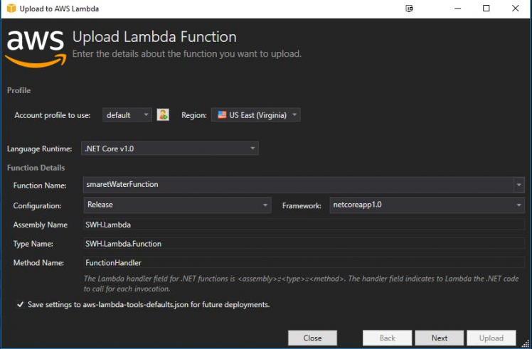 Upload your Lambda
Create C# Models for Alexa Smart Home API
My first thought was that I would model the calls from Alexa to make a nice little library to use in the API. Unfortunately, I found that the contracts that Alexa employs were not very consistent. I might even go as far as to say, they were all over the place. If I had to do it over, I probably would have skipped modeling them and just used dynamics. I don't think the benefits of strong naming outweighed the added complexity of the object graphs. In any respect, you can find the models that i ended up with here in the solution.
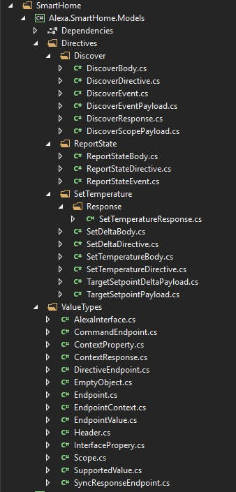 Objectified Alexa Smart Home Contracts
Create MCV Controller to interact with Lambda
With the models in place, I created a new ASP.NET Core Web Application of the Web API variety
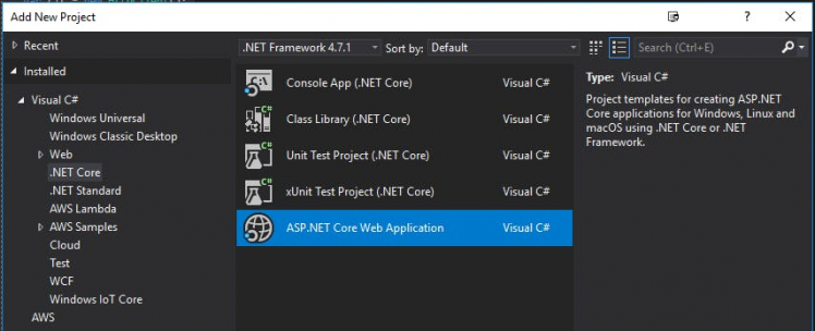 Create new Web App
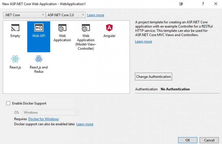 ASP.NET Core 2.0 Web API
In my new web app I created my SmartHome MVC Controller with 4 endpoints that will get calls from the AWS Lambda. Obviously the details are in the repository, but it ended up looking something like this:
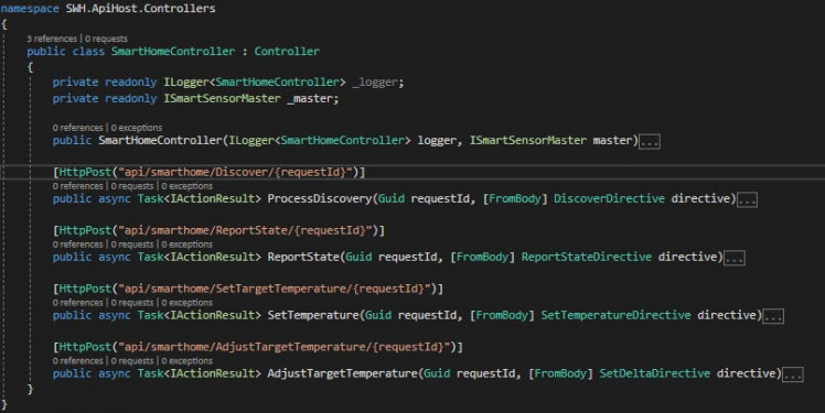 Endpoints Called from AWS Lambda
Service Bus Communication
Now that we have commands flowing in from Alexa, we need to relay that information to our Pi. This is where we are using the service bus. The communication is pretty basic. For the most part, I an just going to send along the access token in the message body and set the "ContentType" property to the command I want the smart water controller to execute. The only exception here is the command to set a new target temperature. For that command, I will just pre-pend the new temp formatted to 3 digits in front of the token and pull it off on the other side.
Here is my message service used in the controller
public class ServiceBusMessenger : ISendMessages
{
   private readonly ILogger<ServiceBusMessenger> _logger;
   private const string ServiceBusConnectionString = "Connection string from Azure Portal";
   private const string QueueName = "commands";
   private static IQueueClient _queueClient;
   public ServiceBusMessenger(ILogger<ServiceBusMessenger> logger)
   {
       _logger = logger;
       _queueClient = new QueueClient(ServiceBusConnectionString, QueueName);
   }
   public async Task SetTemp(int newTemp, string accessToken)
   {
       _logger.LogTrace($"Sending command to set temp to {newTemp}");
       try
       {
           var message = new Message(Encoding.UTF8.GetBytes(newTemp.ToString("00#") + accessToken)) {ContentType = "SET"};
           // Send the message to the queue
           await _queueClient.SendAsync(message);
       }
       catch (Exception e)
       {
           _logger.LogError(e.ToString());
           throw;
       }
   }
   public async Task TurnOn(string accessToken)
   {
       _logger.LogTrace("Sending ON command");
       try
       {
           var message = new Message(Encoding.UTF8.GetBytes(accessToken)) {ContentType = "ON"};
           await _queueClient.SendAsync(message);
       }
       catch (Exception e)
       {
           _logger.LogError(e.ToString());
           throw;
       }
   }
   public async Task TurnOff(string accessToken)
   {
       _logger.LogTrace("Sending OFF command");
       try
       {
           var message = new Message(Encoding.UTF8.GetBytes(accessToken)) {ContentType = "OFF"};
           await _queueClient.SendAsync(message);
       }
       catch (Exception e)
       {
           _logger.LogError(e.ToString());
           throw;
       }
   }
   public async Task ResetStats(string accessToken)
   {
       _logger.LogTrace("Sending reset");
       try
       {
           var message = new Message(Encoding.UTF8.GetBytes(accessToken)) { ContentType = "ZERO" };
           // Send the message to the queue
           await _queueClient.SendAsync(message);
       }
       catch (Exception e)
       {
           _logger.LogError(e.ToString());
           throw;
       }
Create Service to Manage Incoming Messages
I decided to abstract the messaging components in to a service that could just raise standard events to handle on the Pi. The following BusManager service does just that
public class BusManager
{
   public event SetRequestEvent SetRequest;
   public event ZeroRequestEvent ZeroRequest;
   private const string ServiceBusConnectionString = "ConnectionString From Azure Portal";
   private const string QueueName = "commands";
   private static IQueueClient _queueClient;
   public BusManager()
   {
       _queueClient = new QueueClient(ServiceBusConnectionString, QueueName);
       // Register QueueClient's MessageHandler and receive messages in a loop
       RegisterOnMessageHandlerAndReceiveMessages();
   }
   public async Task CloseConnection()
   {
       await _queueClient.CloseAsync();
   }
   protected virtual void OnSetRequest(int newTemp, string token)
   {
       SetRequest?.Invoke(this, new SetRequestEventArgs(newTemp, token));
   }
   async Task ProcessMessagesAsync(Message message, CancellationToken token)
   {
       // Process the message
       var msgBody = Encoding.UTF8.GetString(message.Body);
       var accessToken = msgBody;
       switch (message.ContentType)
       {
           case "SET":
               var newTemp = msgBody.Substring(0, 3);
               accessToken = msgBody.Substring(3);
               OnSetRequest(int.Parse(newTemp), accessToken);
               break;
           case "ZERO":
               OnZeroRequest(accessToken);
               break;
           case "ON":
               OnSetRequest(999, accessToken);
               break;
           case "OFF":
               OnSetRequest(32, accessToken);
               break;
           default:
               //TODO: better handling
               throw new ArgumentOutOfRangeException($"Unhandled message type {message.ContentType}");
       }
       // Complete the message so that it is not received again.
       // This can be done only if the queueClient is opened in ReceiveMode.PeekLock mode (which is default).
       await _queueClient.CompleteAsync(message.SystemProperties.LockToken);
   }
   // Use this Handler to look at the exceptions received on the MessagePump
   static Task ExceptionReceivedHandler(ExceptionReceivedEventArgs exceptionReceivedEventArgs)
   {
       //TODO: Add some exceptioon handling
       return Task.CompletedTask;
   }
   private void RegisterOnMessageHandlerAndReceiveMessages()
   {
       // Configure the MessageHandler Options in terms of exception handling, number of concurrent messages to deliver etc.
       var messageHandlerOptions = new MessageHandlerOptions(ExceptionReceivedHandler)
       {
           // Maximum number of Concurrent calls to the callback `ProcessMessagesAsync`, set to 1 for simplicity.
           // Set it according to how many messages the application wants to process in parallel.
           MaxConcurrentCalls = 1,
           // Indicates whether MessagePump should automatically complete the messages after returning from User Callback.
           // False value below indicates the Complete will be handled by the User Callback as seen in `ProcessMessagesAsync`.
           AutoComplete = false
       };
       // Register the function that will process messages
       _queueClient.RegisterMessageHandler(ProcessMessagesAsync, messageHandlerOptions);
   }
   protected virtual void OnZeroRequest(string token)
   {
       ZeroRequest?.Invoke(this, new SmartWaterCommandArgs(token));
   }
}
Create IoT Core App
For the final piece of the puzzle, we will create a new Windows IoT Core Background Application in our solution that will be deployed to the Pi.
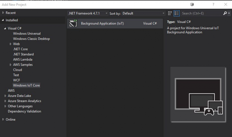 New Background App for the Pi
This application will handle security (verify tokens), manage the LCD display, relay commands from the web to the Arduino and relay status reports from the Arduino to the web.
In the repo you will see the following components to that application:
- BusManager - listens to the service bus and raises events
- SmartSensorManager - communicates with the telnet server on the Arduino (ESP)
- SmartWaterApi - Api to send status reports back to the web server
- DisplayI2C - LCD communication library
Wiring to the Water Heater
The final step is to take it all in to the utility room and hook it up to the water heater. First of all I wired a temp sensor to a the end of a speaker wire that would allow me to attach it to the metal tank itself using a piece of metal tape... You may note that there are only 2 wires because the ground and VDD are both grounded and I am powering the IC using the data line.
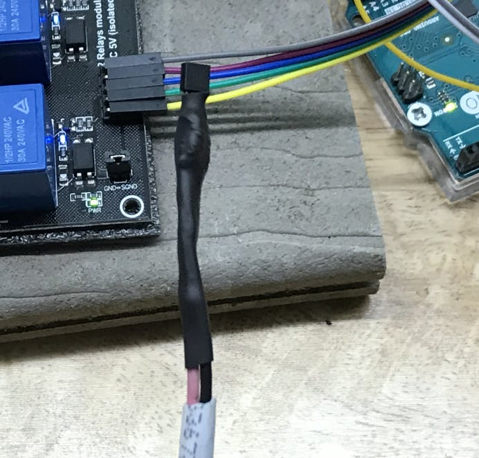 Temperature Sensor Prepared for Mounting
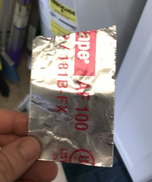 Metal HVAC tape to get the best temp reading possible
 Removing the Access Panel
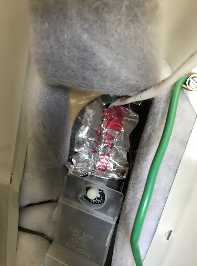 Affix the Sensor
 Looking Good!
!!!! TURN OFF THE BREAKER TO YOUR HEATER !!!
Please Please Please test the lines before you touch them!
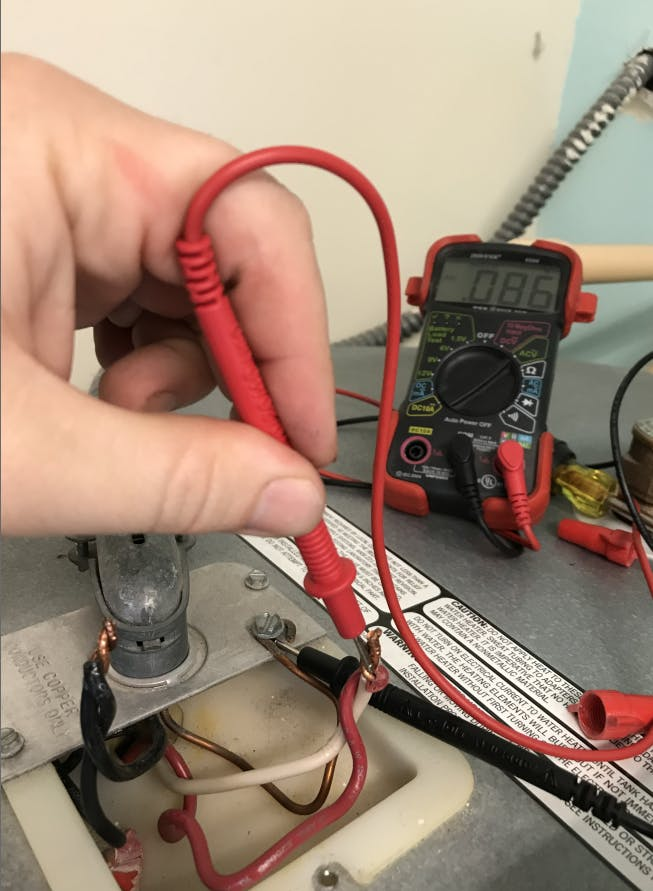 Test to be sure the power is off
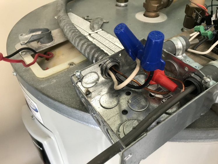 Connect the Supply Line to the Rig
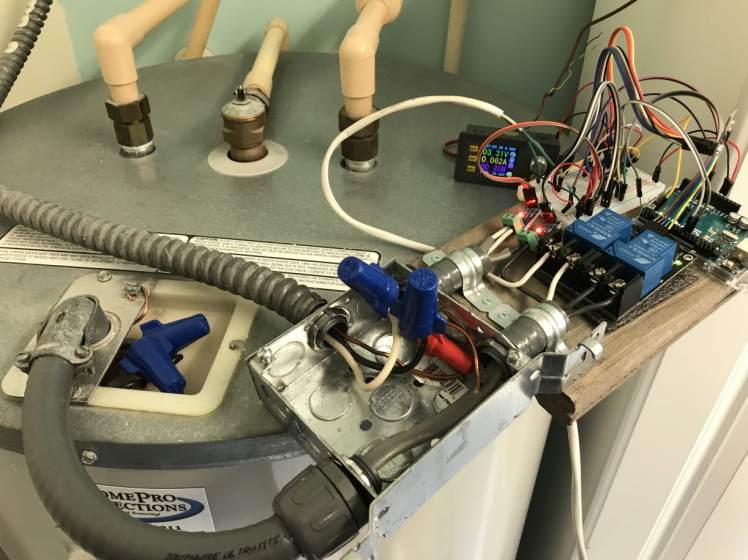 Connect the Output to the Water Heater
If all goes well you should be able to bring up the system and get some good temperature readings!
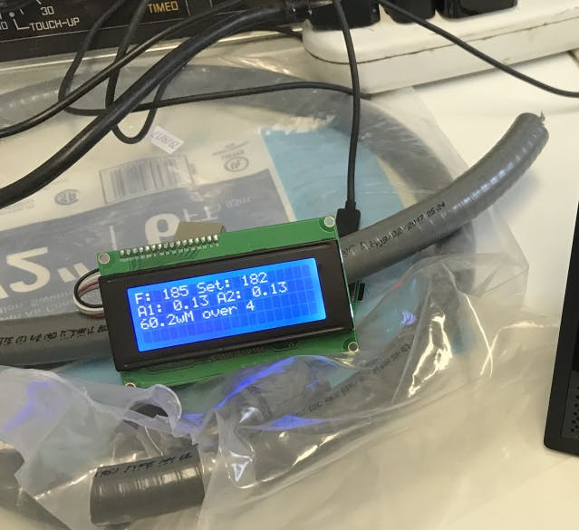 Check the Temperature
Try it out for yourself!
I went through the publishing exercise with Amazon to get the skill out there for you guys! The API is deployed connected to a MOCK SENSOR so it will provide some feedback even though you don't have the live sensor setup to discover.
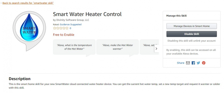 Skill Home Page - SmartWater
For purposes of the Alexa Smart Home Challenge contest, here is the publish date of January 3rd, 2018 within the contest window
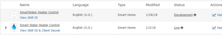 Published January 3rd, 2018
Conclusion
That's about it! Next step would be to build out a nice dashboard where users could come in and setup their heating schedules, review power usage and SAVINGS, etc. Also, with the architecture the way it is, other sensors could be added to the system and managed by the same Raspberry PI *Hallway Unit* or hub. I have a few more ideas that would fit the SmartWater theme... Stay tuned!
The hallway unit itself could be really nice with a touch screen and more extensive web application on it. All-in-all it could be a really sharp little package.
Leave your feedback...