
Additional Analog Inputs In Arduino - Cd4051b Multiplexer

About the project
Sometimes the number of analog inputs on an Arduino just isn't enough for your project, this tutorial is all about using cheap CD4051B multiplexing chips to turn one analog pin into eight!
Project info
Difficulty: Moderate
Platforms: Arduino
Estimated time: 1 hour
License: GNU General Public License, version 3 or later (GPL3+)
Items used in this project
Hardware components

Story
One of the immediate ‘issues’ I noticed with integrating Arduino into music production was the finite number of inputs. Though Arduinos have ample inputs for many uses, musical instruments often have hundreds of things to pluck at, manipulate, and record.Recently, I built a sequencer by Look Mum No Computer (link) – which utilises the Arduino to replace the timer chip in a baby-8 style sequencer and give more expressiveness to the musician. It allows the performer to use buttons to play the sequencer like a keyboard, as well as having a switch to play the sequence backwards. Both of these are things that would have been more difficult to implement without the Arduino.As soon as I put it together, I realised that what I truly wanted to do with a sequencer was to look at the outputs of the potentiometers and manipulate them further in code. The problem was that all 21 of the inputs on the Arduino nano suggested were already in use. To start with, this was really disappointing, but I realised that going back to the breadboard gave me a lot more room to experiment with this project.
What is Multiplexing?
Beyond buying a larger Arduino, one of my first thoughts was to see if there was any way to add more inputs – and multiplexing seemed the most straightforward option! Multiplexers are integrated circuits which act a lot like an automated selector switch (Ahmed and Spreadbury, 1984, p. 263), allowing a system to read the inputs from several sensors in quick succession.
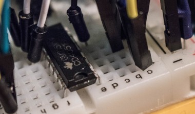
 The CD4051BE chip on the breadboard
I didn’t come across many articles about this chip; most seem to be about the 74HC4051 which may not be in manufacturing anymore. The CD4051BE appears to be functionally identical, however, so I went with it.
Once I’d gotten my head around what the abbreviations on the datasheet meant, the wiring (though reasonably extensive) wasn’t too complicated. If you know how to wire up a potentiometer, most of this is essentially the same but using the outputs on the chip instead of the Arduino to connect the central signal pin. From the CD4051B Datasheet
Common Output/Input (COM OUT/IN: Pin 3)Connect to Arduino signal pin 0
Multiplexed Output/Input Channels (CHANNELS IN/OUT 0-7: Pins 1, 2, 4, 5, 12, 13, 14 & 15)Connect to signal pin (centre) of respective potentiometers
Voltage Emmiter Emmiter, Negative Supply Voltage (VEE)Not connected
Voltage Source Source, Negative Supply Voltage (VSS)Connected to Ground
Voltage Drain Drain, Positive Supply Voltage (VDD)
Connected to 5VA, B, CConnected to Pins 8, 9 & 10 on the Arduino

Breadboard Layout for this Multiplexer Project – Made by Me using FritzingThe Arduino Code
I have included a code based very heavily on the code in Boby Bobs’ video (Bob, 2015) linked at the end of this post, which I used to check whether my multiplexer was working. It will write the readings from each potentiometer to the serial input to verify they are working, and then you can use those analogRead values for whatever you need to.
Boby Bob’s code uses ‘int64_t’ and ‘uint8_t’to set a more specific constant than just using ‘int’ or ‘float’. Using ‘int64_t’ means that the constant is an integer with a bit width of exactly 64 (CPP Reference, n.d.) – there is more information on C++ integers in the references below. I don’t fully understand the reason for choosing these, so I have changed them both to ‘int’ as it was messing up the potentiometer outputs.
One important thing to remember when using this multiplexer chip is that the inputs are not read at the same time, but are instead read in quick succession by sending a binary code from pins A, B & C (10, 9, & 8) alongside the information.
The codes displayed in the table below show the Arduino which pin is being read at which time, as it can create eight different numbers from only three outputs by using binary. These relate to the port numbers in the code, of which the last three digits are the inputs on digital pins 8, 9, and 10. The inhibit state is wired to digital pin 7, and acts as a pause function (Bob, 2015).
Port B maps six digital pins, 8 to 13, plus two more on the crystal pin. This is what the string of eight binary digits is in PORTB=0b00000111. It’s important not to change the first two bits, as this may cause issues with the Arduinos crystal.The DDRB section of code is allowing access to the Port B Data Direction Register – which allows them to be set as inputs or outputs (Arduino – Port Registers, n.d.). PORTB is setting them as high or low. Much more information on this can be found in the arduino.cc help guide referenced.
From the CD4051B Datasheet
My next post explains how you can stack multiple multiplexers together to get even more inputs. The video below also goes through how to write the code in more detail:
References:
2003. CD4051BE Texas Instruments Datasheet. [online] Available at: https://datasheet.octopart.com/CD4051BE-Texas-Instruments-datasheet-7280354.pdf [Accessed 15 November 2020].
Bob, B., 2015. Analog Multiplexer Demultiplexer MC14051B Basic Introduction.. Available at: https://www.youtube.com/watch?v=Q2WMlluVXmo&feature=emb_title [Accessed 15 November 2020].
Ahmed, H. and Spreadbury, P. J., 1984. Analogue and Digital Electronics for Engineers: An Introduction, 2nd ed. Electronics Texts for Engineers and Scientists, Cambridge, Cambridge University Press.
Arduino.cc. n.d. Arduino – Port Registers. [online] Available at: https://www.arduino.cc/en/Reference/PortManipulation [Accessed 24 November 2020].
En.cppreference.com. n.d. Fundamental Types. [online] Available at: https://en.cppreference.com/w/cpp/language/types [Accessed 24 November 2020].
En.cppreference.com. n.d. Fixed Width Integer Types (Since C++11). [online] Available at: https://en.cppreference.com/w/cpp/types/integer [Accessed 24 November 2020].
Battle, S., 2017. Arduino 8 Step Sequencer Keyboard. [online] LOOK MUM NO COMPUTER. Available at: https://www.lookmumnocomputer.com/projects#/sequencer-keyboard [Accessed 9 November 2020].
Code
Credits
Related products


Leave your feedback...