
48-56 Hours Photo Trap Based On Esp32 Cam Module.

Made by rsrman / Garden / Photos & Video / Security / IoT
About the project
Automatic photo trap with motion sensor. 50+ hours working of batteries
Project info
Difficulty: Easy
Platforms: Arduino
Estimated time: 2 hours
License: GNU General Public License, version 3 or later (GPL3+)
Items used in this project
Hardware components


View all
Story
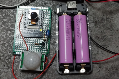
A project based on the ESP32cam module.
Component Required for this ESP32-CAM project:
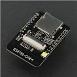
1.ESP32-CAM (AI Thinker)
2. PIR Motion Sensor Module
3.BC547 NPN Transistor
4.220ohm, 1k, 10k Resistor.
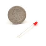
5. LED 5-mm
6. 2x 16850 batteries
7. 16850 Lithium Battery Shield Expansion Board V8.
8. Micro SD card
For the project I replaced the stock camera with a 2MP 21MM-160 650nm camera.
The photo trap lasts between 48-56 hours with charged batteries, during which time it takes about 150 photos with a resolution of 1600x800.
To do this, we need to put the device in deep sleep mode. It is activated only when motion is detected by the PIR sensor.
The sensitivity of the PIR sensor can also be adjusted, as well as the range - MAX 7 meters. (as in my case)
The presence of 8250a in 16850 Lithium Battery Shield Expansion Board V8. Protects batteries from overcharging and discharging,
As during the test, the device turned off at 3.12V (after 54 hours of continuous operation).
Expansion Board V8 has a HOLD mode. This mode supplies current to the module continuously until the 8250a's protection trips.
Please note that the CAM module and the entire circuit requires a 5V DC power supply. This can be done in several ways.
I used the built-in output of the USB-A type on the board.
After some tests, I decided to collect everything in a waterproof box. (surely it can be done better :))
I will upload the code I used later on github.
Enjoy
Schematics, diagrams and documents
Code
Credits
Related products


Leave your feedback...