
How to Set Up an ESP32 Wireless Microcontroller as a General Purpose Processor Using the Arduino IDE
The ESP32 is a powerful, feature-packed, SoC that can be effectively used in many applications. For all its features, it is surprisingly affordable.
While generally known for its Wi-Fi and Bluetooth ability, it can nonetheless be used as a general-purpose computing platform, due to its favorable cost to benefits ratio. This is the focus of this article.
Strictly, the ESP32 refers to the actual system-on-chip (SoC). However, in this article, ESP32 will refer to the ESP32 module which consists of the actual SoC, external SPI flash, LDO, antenna, and other support hardware, all integrated on a single board.
In particular, the focus will be on what is generally known as the ESP32 Development Module.
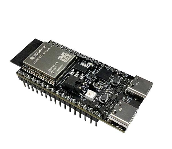
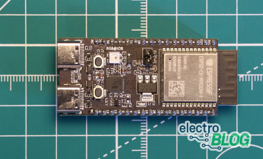
It contains a CP2102 serial to USB chip, two pushbuttons, two LEDs, and a voltage regulator, in addition to the actual ESP32 module. This allows for easy interfacing to a cross-development platform, such as a Windows PC. A USB cable will be the only additional hardware required.
Once the FW development is done, it is quite straightforward to replace the development module with an actual ESP32 module that is integrated with the rest of the hardware.
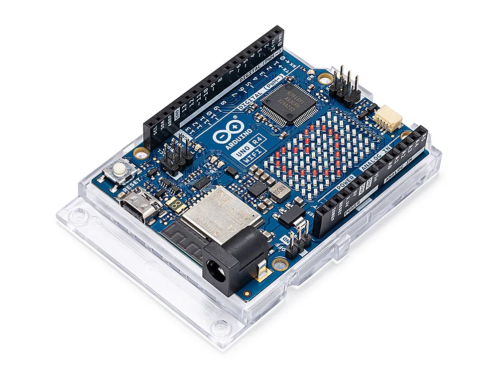
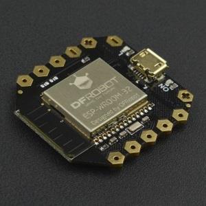
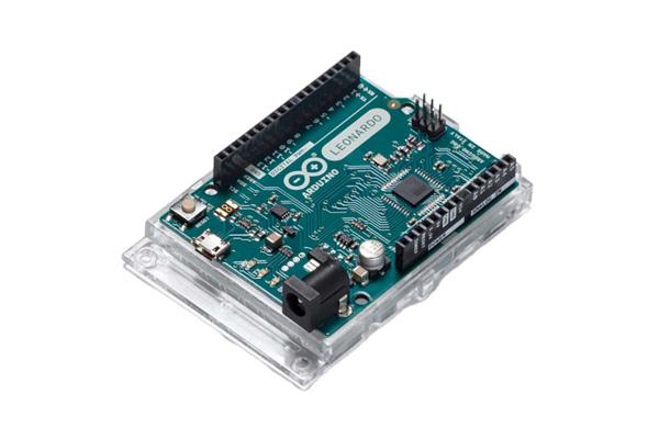
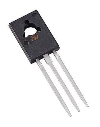
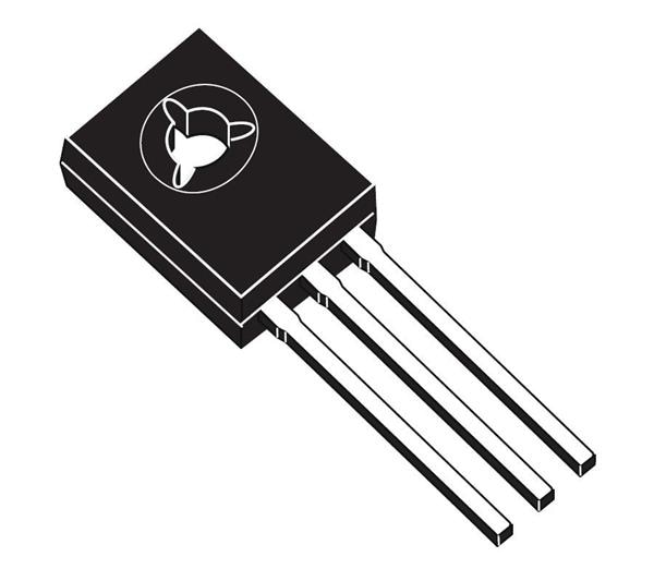
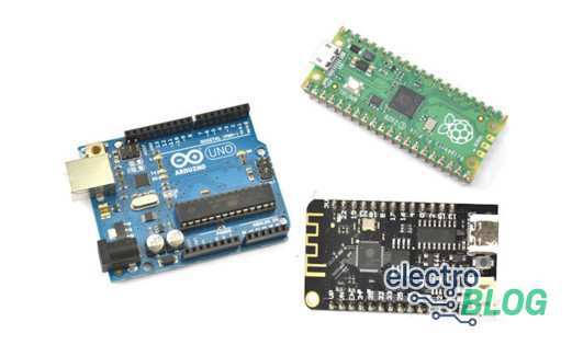
The ESP Development board is shown is figure 1 below. A couple of different versions of the development module are shown in figure 2. To actually program the ESP32 Module prior to being used in user-designed hardware, a simple programmer such as the one shown in Figure 3 can be used.
It basically includes the interfacing hardware that is integrated into the development board so that, in the end, the ESP32 Module can be detached and integrated into the user hardware.
For the firmware section, the Integrated Development Environment (IDE) will be the Arduino. It is easier to use than the official IDF or IoT Development Framework from Espressif Systems, the maker of the ESP32 SoC.
Despite its quirks, Arduino is much easier to set up and use. It can accomplish almost everything that the Espressif IDF can do. The only exceptions would be in a few extreme cases where some rarely used functions of the Application Programmer’s Interface (API) are needed.
The API documentation is quite extensive, and it may take some intense reading to become comfortable with it.
The ESP32 has quite a bit of power to burn in most applications, and the burden of using Arduino in most cases more than compensates for the additional complexity of mastering the Espressif IDF and API.
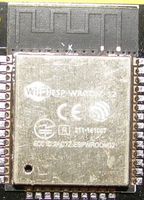 Figure 1 - ESP32 Module
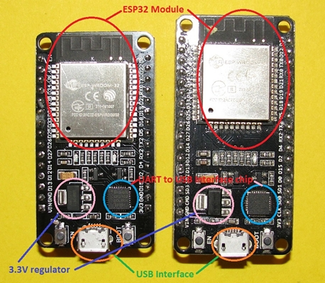 Figure 2 – Examples of ESP32 Development Modules
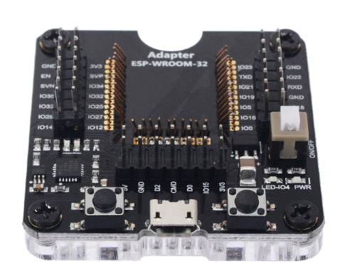 Figure 3 – ESP32 Module programmer
Install the ESP32 Board in Arduino IDE
The first thing to do when trying to use the ESP32 with the Arduino IDE is to properly set it up. The Arduino IDE can accommodate many different processor modules in addition to actual Arduino boards such as the Uno, or Mega etc. This is done by installing a “board” in the Arduino IDE.
Start with a fresh Arduino IDE install that can be downloaded from the Arduino website. Figure 4 shows that the ESP32 is not initially included in the list of supported boards. So, the first thing to do is to actually install the ESP32 board.
In the Arduino IDE, go to File -> Preferences, and in the Additional Boards Manager URLs input field, type:
https://dl.espressif.com/dl/package_esp32_index.json
Then go to Tools -> Board “current board selection” -> Board Manager. In the pop-up window, scroll down to the bottom, and install the ESP32 by Espressif Systems boards. This is shown in figure 5 below. The Arduino IDE is now ready for development of ESP32 applications.
To check if everything was done correctly, just run the simple blink program from File -> Examples. Some familiarity with compiling and running programs in Arduino is assumed here. So, this part will not be further expanded upon.
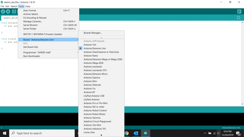 Figure 4 - Available boards from the Board Manager at initial install
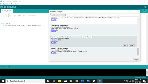 Figure 5 – Board Manager screen after installing the ESP32 board
Pin Usage for the ESP32
While the ESP32 has many available pins, unfortunately not all pins are created equal. To write firmware that works properly, it is essential to know which pins are usable for a given application.
Figure 6 shows the pinout of one version of the Dev board, and all their possible functions. Not all pins are brought out in all versions. However, what is available in a given board version is consistent in all versions, including the ESP32 Module.
Table 1 shows the possible pins that can be used for digital inputs. For digital output, again some pins are used internally by the ESP32 for various functions, and some pins simply do not have output drivers in the ESP32 SoC.
Table 2 shows the available pins for digital outputs. For analog inputs, GPIO pins 32 to 36, and 39 if available, can be used. For analog output, the two DAC outputs on pins 25 and 26 can be used to give out true analog outputs.
The ESP32 does not currently have PWM analog output functions, so the Arduino analogWrite will not work. There are, however, libraries that can be used to generate PWM on any ESP32 output pin.
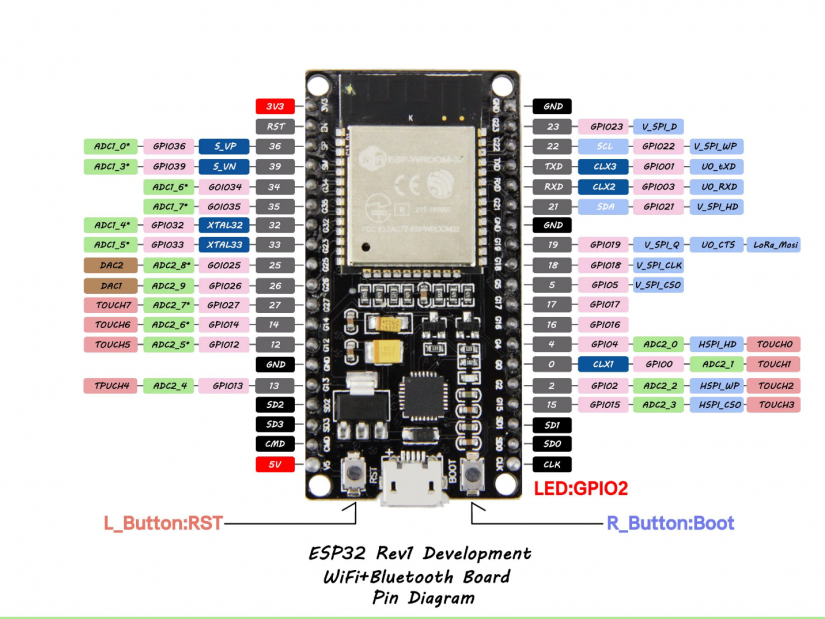 Figure 6 – Pinout of a typical ESP32 Dev module
| GPIO Pins | Usage | Notes |
| 0 - 5 | General-purpose | Can be used for both INPUT_PULLUP or INPUT_PULLDOWN |
| 6 - 11 | Do not use | Internally used to access the SPI flash memory. In some board versions, these pins are not brought out. In some others, these are labeled SD1, SD2, SD3, SD4, and CMD |
| 12 - 33 | General-purpose | Can be used for both INPUT_PULLUP or INPUT_PULLDOWN |
| 34 - 39 | GP. No internal pullup | If input pull-up is needed, this has to be supplied by an external pull up resistor on the input pin |
Table 1 – ESP32 pin usage as digital inputs
| GPIO Pins | Usage |
| 2 | Connected to the internal LED on the Dev board. Available in the ESP32 Module |
| 4, 12 | Can be used as digital outputs. |
| 16 - 19 | Can be used as digital outputs. |
| 21-22 | Can be used as digital outputs. |
| 25 - 27 | Can be used as digital outputs. |
| 32 -33 | Can be used as digital outputs. |
Table 2 – ESP32 pins that can be used for digital outputs
FreeRTOS on the ESP32
Moving on to the firmware, one of the features of the ESP32 is that it natively runs a customized version of FreeRTOS as its operating system. Thus, it supports running multiple independent tasks concurrently. It implements a prioritized preemptive scheduling, with time slicing, for the tasks that it runs.
That essentially means that tasks with higher priorities will preempt tasks with lower priorities, and tasks with the same priorities will timeshare. The task priorities are set by the user at the task invocation, but can be changed afterward.
It is the responsibility of the programmer to properly determine task priorities. For example, it is not a good idea to set a busy loop delay in a high-priority task because lower priority tasks might not get a chance to actually run at all. In any case, there are better alternatives to busy loop delays when using the ESP32.
It is not possible in this article to go over all the features of FreeRTOS. However, a will provide a couple of fully working examples in this section. You can find more information on the ESP32 FreeRTOS here.
As a first example of how FreeRTOS can simplify the code, consider an application where the design does not have a full display due to cost or space reasons. It only has a couple of LEDs to indicate its state.
These LEDs need to be able to blink various states, or codes, even while the system is busy doing other things. Typically, implementing this properly would involve timers and interrupts. Here is a version for the ESP32 that uses its multitasking abilities.
// Define output pin for the LED drive
#define S_LED1_IO 2
// Some blink patterns. Patterns are 16 bits. 1 means LED is ON for one time period.
// This can be extended to 32 bits for more flashing patterns. Just change the uint16_t
// to uint32_t, and define 32-bit flashing patterns. Then slightly modify the LEDFlash function
const uint16_t LED_ON = 0b1111111111111111;
const uint16_t LED_OFF = 0b0000000000000000;
const uint16_t LED_FSTFLASH = 0b1010101010101010;
const uint16_t LED_MEDFLASH = 0b1111000011110000;
const uint16_t LED_SLOFLASH = 0b1111111100000000;
const uint16_t LED_BEEP_1 = 0b1100000000000000;
const uint16_t LED_BEEP_2 = 0b1100110000000000;
const uint16_t LED_BEEP_3 = 0b1100110011000000;
// This global variable is used to set the current LED flash pattern
uint16_t LEDFlashPattern = LED_OFF;

// Function to set up the separate LED task
void LEDTaskSetup(void)
{
// Set up the digital IO port to control the LED's
pinMode(S_LED1_IO, OUTPUT);
// Create a separate thread to handle LED flashing
xTaskCreate(
LEDFlash, // Pointer to the function implementing the actual task
"LED_Flash", // Descriptive name
1000, // Task stack allocation. 1000 bytes is sufficient for this task
NULL, // Pointer to task parameter passed to the task. None here
1, // Priority of 1 – Low priority.
NULL); // Pass a reference to a variable of type TaskHandle_t if task handle needed
} // End LEDTaskSetup
// The actual LED flashing task

void LEDFlash(void *pvParameters)
{
static uint8_t bitPos = 0;
while(1) // FreeRTOS tasks must never exit on their own. They must properly terminated to stop them, if needed.
{
// Scan through each bit position of LEDFlashPattern, and control the LED accordingly
if (bitRead(LEDFlashPattern, bitPos)) digitalWrite(S_LED1_IO, HIGH);
else digitalWrite(S_LED1_IO, LOW);
vTaskDelay(pdMS_TO_TICKS(100)); // Each time period is 100 ms. Change as required
if (++bitPos == 16) bitPos = 0; // Assuming 16-bit flashing pattern here
}
}

void setup()
{
// Set up LED flashing task. From now on, the LED will flash any pattern, including ON or OFF, that is
// currently loaded in LEDFlashPattern by any function.
LEDTaskSetup();
// Other setup code here…
}

Void loop()
{
// User code here…
}
One other thing about this task is that, by default, it runs on core 1 of the ESP32. Core 0 is generally dedicated to running the ESP32 wireless functions. However, if no wireless functionality is needed in an application, it is possible to force the task to run on core 0, thus freeing core 1 to run the rest of the user application.
To achieve this, just replace the xTaskCreate function in function LEDTaskSetup with this one:
xTaskCreatePinnedToCore(
           LEDFlash,            // Pointer to the function i8mplementing the actual task
          "LED_Flash",      // Descriptive name
          1000,                    // Task stack allocation. 1000 bytes is sufficient for this task.
          NULL,                    // Pointer to task parameter passed to the task. None here
          1,                           // Priority of 1 – Low priority.
          NULL,                    // Pass a reference to a variable of type TaskHandle_t if task handle needed
          0);                          // Run task on Core 0
Here is another example of how the ESP32 FreeRTOS can be quite handy. It is often required to run a function periodically such as reading the temperature sensor every minute or two.
Using a busy loop delay is not practical since the whole program stops during the delay. One way to do this is to have a timer interrupt with the proper delay, and then call the desired function when the interrupt occurs, usually by setting a flag that can then be polled to determine if it is time to call the function.
This ties up one timer. If there are many such periodic tasks, the Interrupt Service Routine must set many such flags, each with an associated counter to implement the proper delay to set the flag for each function call. Each flag must then be checked to determine which function to run. In the ESP32, this can be accomplished by setting up FreeRTOS SW timers. An example follows.
// This is a somewhat contrived example that simply uses a SW timer to periodically call a function
// to flash the ESP32 Dev Module built-in LED. The callback function can, of course, do any other
// processing besides.
// The IO pin for the built-in LED.
#define LED_Drive 2
// Callback function. Make sure that this function does not hog the processor because once
// called, the rest of the application will not run until this function returns.
void swTimerCB(TimerHandle_t timer)
{
  static bool LED_State = true;
  // Toggle built-in LED
  if (LED_State = !LED_State) digitalWrite(LED_Drive, false);
  else digitalWrite(LED_Drive, true);
}
void setup()
{
  // Set up digital IO ports to control the LED
  pinMode(LED_Drive, OUTPUT);
  // Create timer.
  // xTimerCreate parameters are: Name (anything really), pdMS_TO_TICKS macro parameters are in ms,
  // pdTRUE means repeat (Change to pdFALSE for one shot),
  // 0 is the timer ID of this timer. It is possible to create multiple SW timers that call the same
  // callback function. This callback function can then determine which SW timer called it by making a call
  // to another FreeRTOS function called pvTimerGetTimerID().
  // swTimerCB is a pointer to a callback function to be executed - Essentially the name of a function.
  TimerHandle_t timer1 = xTimerCreate("swOneSecTimerCB", pdMS_TO_TICKS(1000), pdTRUE, 0, swTimerCB);
    // Make sure timer was successfully created. The second parameter is the number of ticks to wait
  // before starting timer.
  if (timer1 != NULL) xTimerStart(timer1, 0);
  // Rest of setup function goes here...
}
void loop()
{
  // Application code here...
}
Using the ESP32 on the Arduino IDE
This section applies to using the Arduino IDE in general, but is particularly relevant to the ESP32 since it has a large application code space that could be used to write rather large applications.
While it is possible to write an entire application in one large file, it is much better to break down the application into multiple files that can be more easily handled. The Arduino IDE can support many tabs which can make the application more manageable.
However, one important thing to note is that a tab in the Arduino IDE is not a separate module that is separately compiled and linked to produce the executable binary. In the end, behind the scene, Arduino simply combines all the tabs into one single module.
This quirk can cause some issues. Consider figure 7, where this simple Arduino project has five tabs, with the A_Tab tab shown. Figure 8 shows the contents of the B_Tab. Assuming that the other tabs are blank, this project will absolutely compile properly.
If the tabs were really separate modules, there would have been a linker error due to an unresolved reference to variable_ATab since it was declared static in A_Tab.
Since, as mentioned, the tabs are combined together into one module, the static keyword in A_Tab is actually quite useless here. This variable is in scope in B_Tab.
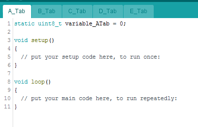 Figure 7 – Arduino project with five tabs
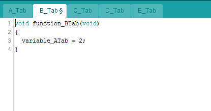
Figure 8 – Contents of B_Tab
Now consider the simple C_Tab and B_Tab as shown in figures 9 and 10. Compiling this will result in an error in B_Tab due to an unresolved reference to variable_CTab.
What happens is the offending line in B_Tab is forward referencing variable_CTab since the content of B_Tab will be appended to the overall module before the content of C_Tab. Modifying B_Tab as shown in figure 11 solves the forward reference issue. The compiler is now made aware of the fact that variable_CTab is declared somewhere else.
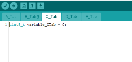 Figure 9 – New content of C-Tab
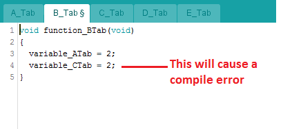 Figure 10 – New content of B_Tab
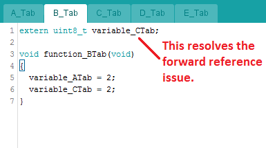 Figure 11 – Modified B_Tab to resolve forward reference issue
Additionally, the order of the tabs does not really matter. Arduino concatenates the tabs lexicographically – i.e, in the same order as they would appear in a dictionary.
So, in the IDE there might be tabs named: A_Tab, C_Tab and B_Tab in that order from left to right. However, the tabs are really combined in this order: A_Tab, B_Tab and C_Tab.
The only exception to this rule is that the left most tab is always the first tab, regardless of its lexicographical order. Following this example, it can be called Z_Tab, but it will still be the first tab, while the rest of the tabs are ordered lexicographically.
So, a global variable defined in B_Tab will still be in scope in any function defined in C_Tab even though in the actual IDE, C_Tab appears before B_Tab. Given that, it is a good idea to precede each tab with A_tabname, B_tabname, and place them in order from left to right in the Arduino IDE. That way, the tabs will be combined from left to right.
It should also be noted that the above issues can be resolved by naming the tabs with a .cpp or .h extension as appropriate. Modules with these extensions are actually separate modules, and are compiled separately. In such cases, also add a <Arduino.h> header file to each such tab since this is not automatically included in cpp files as they are in .ino files.
Finally, we get to the Arduino libraries. It is one of the great things about the ESP32, but also one of its biggest source of issues. In Arduino, the libraries are not pre-compiled object modules that are then linked with the user object modules.
They are actually C++ source code modules that are also compiled at the same time as the user application code, and linked into the final binary. It is actually quite easy to view and edit them. In Windows, they are usually in this folder:
Users/<your UserName>/documents/Arduino/libraries.
Each “library” is then given its own individual folder. Having acess to the source codes is great, as it allows relatively easy modifications, and often times this is absolutely required.
Some user-contributed libraries embed websites and other information in their libraries, and in most cases this has to be changed to suit the actual application. One pitfall is that sometimes these libraries get updated in a manner that is inconsistent with its use in a current application.
For example, the author might update a given function in such a way as to render it incompatible with what the current application needs. The Arduino IDE will sometimes show a pop-up about new versions of libraries, and care should be exercised in actually deciding to upgrade to a newer version to make sure that existing applications do not suddenly fail to run properly when they are uploaded into a new module.
This is because Arduino recompiles everything before uploading, and will pick up the newly installed library instead of the original one. Of course, all modifications made to the library to suit a given application will be lost when the new version overwrites the existing version.
One way to get around this issue is to rename all current critical libraries to something else, and update all references to use the new name. That way, these libraries are frozen in their current states.
ESP32 Wireless Microcontroller as a General Purpose Processor Using the Arduino IDE - Final Thoughts
The ESP32 is a powerful microcontroller with many features including built-in Wi-Fi and Bluetooth wireless radios. The ESP32 can be used in many applications. One of the most amazing benefits of the ESP32 that even with all of these features it is a very affordable solution.
In this article, we’ve discussed how the ESP32 can even be used as a general processor in applications not requiring any wireless features. This is partially due to its very low cost even compared to non-wireless processors.

John Teel is the founder of Predictable Designs, a company that helps entrepreneurs bring new electronic products to market. John was formerly a design engineer for Texas Instruments where he developed microchips now used in millions of products. He also developed his own hardware product that sold in hundreds of retail locations. Check out his free Ultimate Guide – 'How to Develop and Sell Your New Electronic Hardware Product'.


Leave your feedback...