
Arduino Nano Esp32 Handheld Gaming Console - It Plays Doom!

Made by knaveen / Displays / Games & Gaming / Retro Tech
About the project
Create your handheld gaming console using an Arduino Nano ESP32 and play Doom on the go.
Project info
Difficulty: Moderate
Platforms: Adafruit, Arduino, Seeed Studio, Espressif, M5Stack
Estimated time: 5 hours
License: MIT license (MIT)
Items used in this project
Hardware components

View all
Story
Doom is a classic first-person shooter game developed and published by id Software in 1993. The game is set in a futuristic sci-fi world, where the player takes the role of a space marine who must fight his way through hordes of demons from Hell. Doom is regarded as one of the most influential and popular games ever, spawning numerous sequels, spin-offs, and adaptations. Many gamers who grew up in the 1990s feel nostalgic about playing DOOM when they were younger.
Doom was primarily developed in the C programming language, with a few components written in assembly language. The developers used NeXT computers running the NeXTSTEP operating system. The game's level and graphical data were stored separately from the engine in WAD files, which stands for "Where's All the Data?". This enabled easy modification of the design without altering the engine code.
The original DOOM game required at least 4MB of RAM and 20MB of disk space, which are much larger than the typical microcontroller specifications. To port the game, some compression and optimization techniques are needed to fit the game data and code into the microcontroller's flash memory and RAM and some modifications and adaptations are needed to make the game engine run on a different platform and architecture, such as an ESP32 or RP2040 chip. However, these changes may introduce some errors or differences in the game's behavior and performance, which may affect the gameplay experience.
Lately, there have been several efforts to make the game compatible with low-powered microcontrollers. For our project, we've opted to use Retro-Go, an open-source firmware that allows retro games to be played on ESP32-based MCUs. While this firmware doesn't support Arduino Nano ESP32 directly, its flexibility and configurability make it possible to be ported to other ESP32-based MCUs.
Hardware Selection
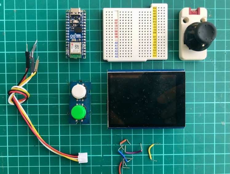
The main objective of this project is to demonstrate the feasibility and performance of running DOOM on a microcontroller with limited resources and capabilities. In this project, we have ported the classic DOOM game on an Arduino Nano ESP32 and used an Adafruit 2.8" TFT display shield, an M5Stack Joystick unit, and Seeed Grove Dual buttons to make it a handheld gaming console.
Connection
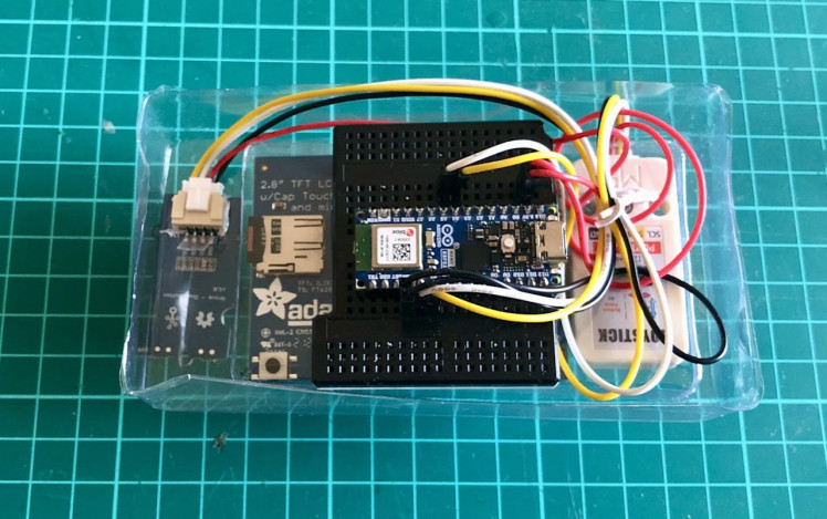
The Adafruit TFT display shield is connected to the Arduino Nano ESP32 via the SPI interface using jumper wires and a stackable breadboard shield.
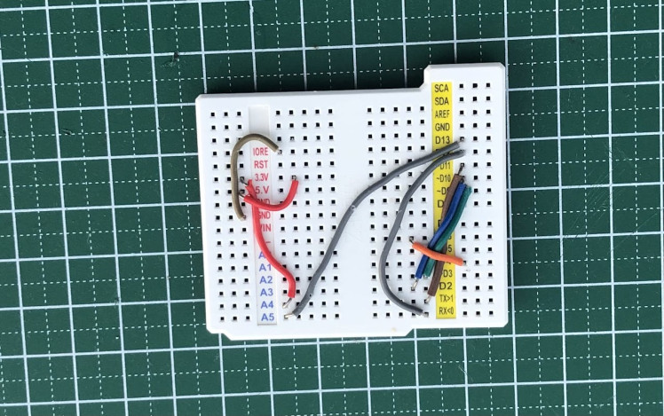
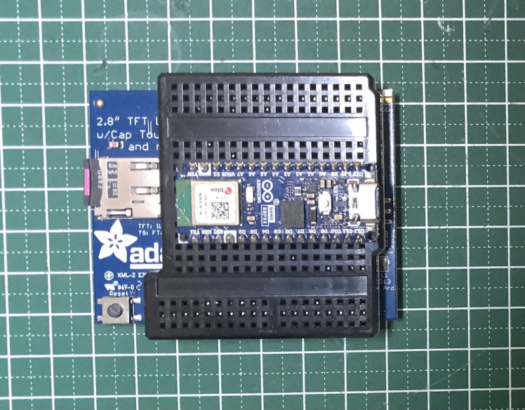
The Arduino Nano ESP32 is placed at the back of the breadboard shield, on top of the stack.
The Joystick and buttons are connected via I2C and GPIO connections respectively, using a male jumper to Grove 4-pin conversion cable. The connection diagram is given in the Schematics section.
Setup development environment
Although we will compile the firmware on macOS, the workflow is similar for other operating systems. First, we need to download and install the ESP-IDF development framework.
$ mkdir ~/Nano_ESP32_DOOM
$ cd ~/Nano_ESP32_DOOM
$ git clone -b release/v4.4 https://github.com/espressif/esp-idf
$ cd esp-idf
$ ./install.sh
$ source export.sh
Now we can clone the Retro-Go repository.
$ cd ~/Nano_ESP32_DOOM
$ git clone https://github.com/ducalex/retro-go
$ cd retro-go
Configuration
The Retro-Go firmware codebase is configurable. They provide a few ESP32-based development board configuration files. We need to add/modify some of the configurations for Arduino Nano ESP32. In thebaseS3.sdkconfig file, add the following lines.
CONFIG_ESPTOOLPY_FLASHMODE="qio"
CONFIG_ESPTOOLPY_FLASHSIZE_16MB=y
We will be re-using components/retro-go/targets/esplay-s3/config.h for the Arduino Nano ESP32, which is based on the ESP32-S3. We need to provide GPIO, I2C, and SPI pins for various components, such as buttons, joystick, TFT display, and SD card, to connect with the Arduino Nano ESP32 board.
// Target definition
#define RG_TARGET_NAME  "ESPLAY-S3"
// Storage
#define RG_STORAGE_DRIVER  1  // 0 = Host, 1 = SDSPI, 2 = SDMMC, 3 = USB, 4 = Flash
#define RG_STORAGE_HOST  SDMMC_HOST_SLOT_1  // Used by driver 1 and 2
#define RG_STORAGE_SPEED SDMMC_FREQ_DEFAULT // Used by driver 1 and 2
#define RG_STORAGE_ROOT  "/sd"  // Storage mount point
// Video
#define RG_SCREEN_DRIVER 0  // 0 = ILI9341
#define RG_SCREEN_HOST SPI2_HOST
#define RG_SCREEN_SPEED  SPI_MASTER_FREQ_40M
#define RG_SCREEN_TYPE 0
#define RG_SCREEN_WIDTH  320
#define RG_SCREEN_HEIGHT 240
#define RG_SCREEN_ROTATE 0
#define RG_SCREEN_MARGIN_TOP 0
#define RG_SCREEN_MARGIN_BOTTOM  0
#define RG_SCREEN_MARGIN_LEFT  0
#define RG_SCREEN_MARGIN_RIGHT 0
// Input
#define RG_GAMEPAD_DRIVER  3  // 1 = GPIO, 2 = Serial, 3 = I2C
#define RG_GAMEPAD_HAS_MENU_BTN  0
#define RG_GAMEPAD_HAS_OPTION_BTN  0
#define RG_GAMEPAD_MAP {
{RG_KEY_SELECT, RG_GPIO_GAMEPAD_SELECT},
{RG_KEY_A, RG_GPIO_GAMEPAD_A},
}
// Buttons
#define RG_GPIO_GAMEPAD_SELECT GPIO_NUM_5
#define RG_GPIO_GAMEPAD_A  GPIO_NUM_6
// Status LED
#define RG_GPIO_LED  GPIO_NUM_45
// I2C BUS
#define RG_GPIO_I2C_SDA  GPIO_NUM_11
#define RG_GPIO_I2C_SCL  GPIO_NUM_12
// SPI Display
#define RG_GPIO_LCD_MISO GPIO_NUM_47
#define RG_GPIO_LCD_MOSI GPIO_NUM_38
#define RG_GPIO_LCD_CLK  GPIO_NUM_48
#define RG_GPIO_LCD_CS GPIO_NUM_21
#define RG_GPIO_LCD_DC GPIO_NUM_18
// SPI SD Card
#define RG_GPIO_SDSPI_MISO  GPIO_NUM_47
#define RG_GPIO_SDSPI_MOSI  GPIO_NUM_38
#define RG_GPIO_SDSPI_CS  GPIO_NUM_9
#define RG_GPIO_SDSPI_CLK GPIO_NUM_48
For the joystick and buttons, we need to add the following lines in the components/retro-go/rg_input.c file.
...
#elif RG_GAMEPAD_DRIVER == 3 // I2C
uint8_t data[3];

if (rg_i2c_read(0x52, -1, &data, 3))
{
  int joyX = data[0];
  int joyY = data[1];
  int btnS = data[2];

  if (joyY > 160) {
    state |= RG_KEY_UP;
  } else if (joyY < 96) {
    state |= RG_KEY_DOWN;
  }

  if (joyX > 160) {
    state |= RG_KEY_RIGHT;
  } else if (joyX < 96) {
    state |= RG_KEY_LEFT;
  }

  if (btnS) {
    state |= RG_KEY_START;
  }
}

for (size_t i = 0; i < keymap_size; ++i)
{
  if (!gpio_get_level(keymap[i].src)) {
    state |= keymap[i].key;
    RG_LOGI("key=%dn", i);
  }
}
...
Build firmware
The Retro-Go firmware offers a Python script that automates the compilation process. Execute the following commands to build the Retro-Go launcher app and the Prboom-go app (Doom port).
$ chmod +x rg_tool.py
$ ./rg_tool.py --target arduino_nano_esp32 build-img prboom-go
Prepare SD card
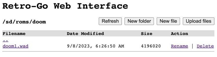
We require an SD card formatted with FAT32 to store settings and save gaming sessions. Also, we would need to copy the WAD file for Doom to the <root>/roms/doom directory on the SD card.
$ cp prboom-go/components/prboom/data/doom1.wad /Volumes/SD/roms/doomThe SD card is inserted into the Adarfruit TFT Display shield.
Flash firmware
To upload the firmware onto the Arduino Nano ESP32 board, simply execute the following command.
$ esptool.py --chip esp32s3 write_flash --flash_size detect 0x00 retro-go_1.39-pre-dirty_esplay-s3.imgEnable WiFi
It is possible to enable WiFi automatically by creating a configuration file with the settings in <root>/retro-go/config/wifi.json on the SD card.
{
  "ssid": "your_router_ssid",
  "password": "your_network_password"
}
After establishing a successful network connection, it will synchronize the time with the NTP server. Entering the IP address of the Arduino Nano ESP32 Wi-Fi interface allows access to a web interface to browse/upload SD card files.
Casing
For quick prototyping, we repurposed a clear PET plastic that was borrowed from the packaging to give the device's front panel a handheld gaming console look and feel, which also provides additional firmness for the joystick and buttons. However, a 3D-printed case would have been a better choice.
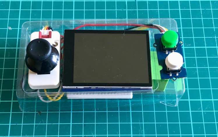
The backside is left uncovered or without any covering.
Demo
Conclusion
We have successfully ported Doom and achieved acceptable performance on an Arduino Nano ESP32. The game is playable at an average frame rate of 34 FPS with a resolution of 320x240 pixels. The device is compact, lightweight, and user-friendly. It also has a retro and nostalgic appeal, as it recreates the original DOOM experience on modern hardware. I hope you enjoyed this project as much as I did. Thank you for your attention.
Schematics, diagrams and documents
Credits
Related products


Leave your feedback...