
Ch32v003 Fm Radio Receiver

Made by wagiminator / 3D Printing / Displays / Music
About the project
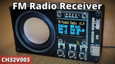
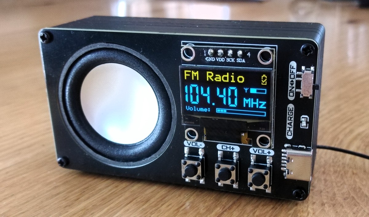
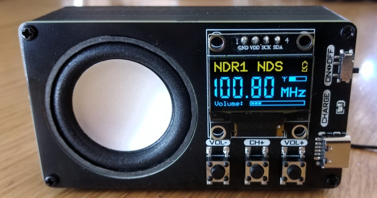
Portable Digital FM Radio Receiver with RDS
Project info
Difficulty: Moderate
Platforms: RISC-V
Estimated time: 3 hours
License: Creative Commons Attribution-ShareAlike CC BY-SA version 4.0 or later (CC BY-SA 4+)
Story
CH32V003 FM Radio Receiver with RDS
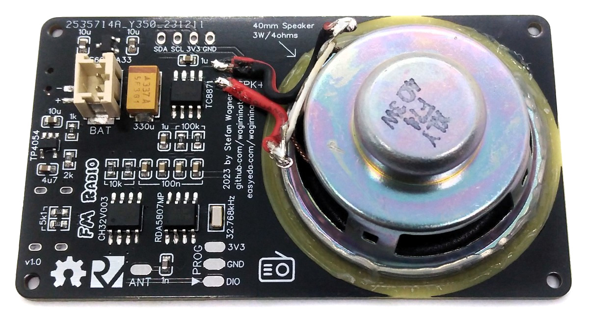
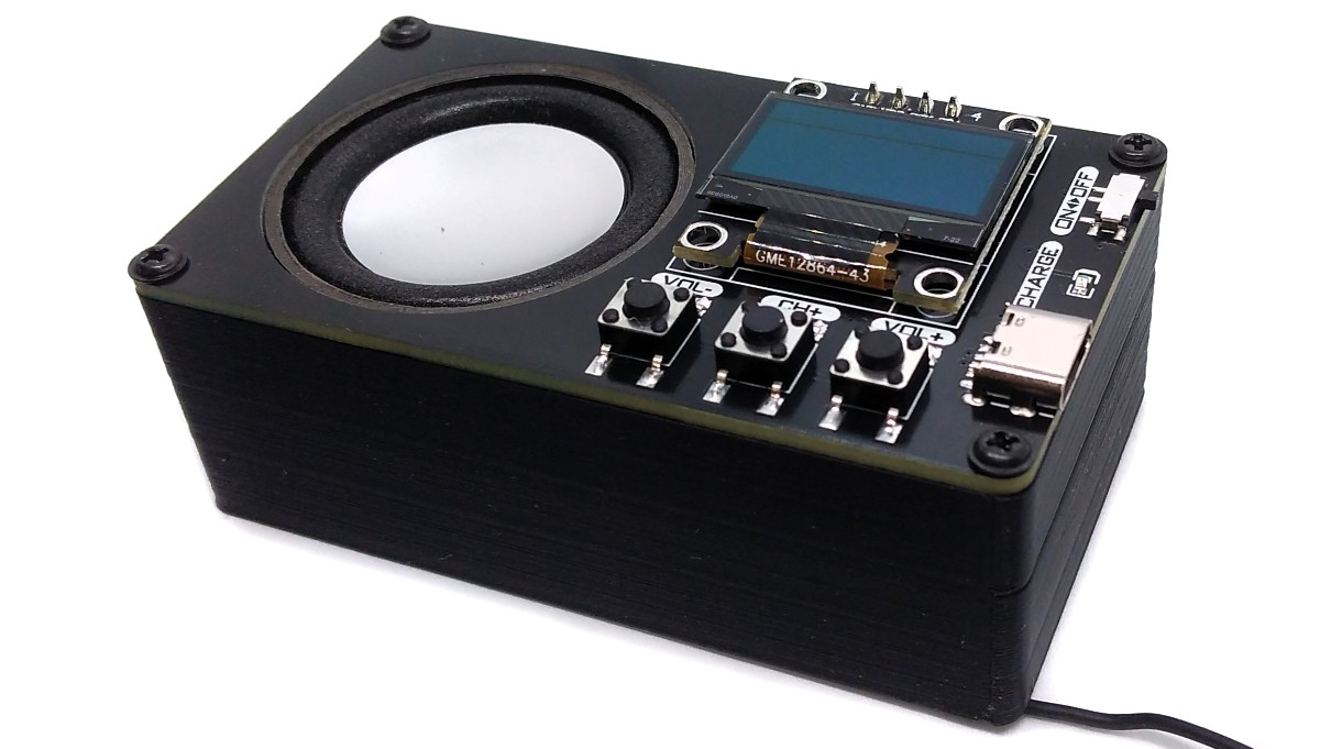
With the portable Li-Ion battery powered FM radio receiver you can listen to your favourite radio station. This device is equipped with cost-effective components, including a CH32V003J4M6 32-bit RISC-V microcontroller, a RDA5807MP FM radio tuner IC, an audio amplifier (TC8871 or XPT8871), a 128x32 pixel OLED display (SSD1306), and a Li-Ion battery charger (TP4054 or MCP73831). You can directly connect a protected 3.7V LiPo battery, a 3W / 4Ω speaker, and an FM antenna. The FM Radio Receiver is a port from the ATtiny412 version.
Hardware
Schematic
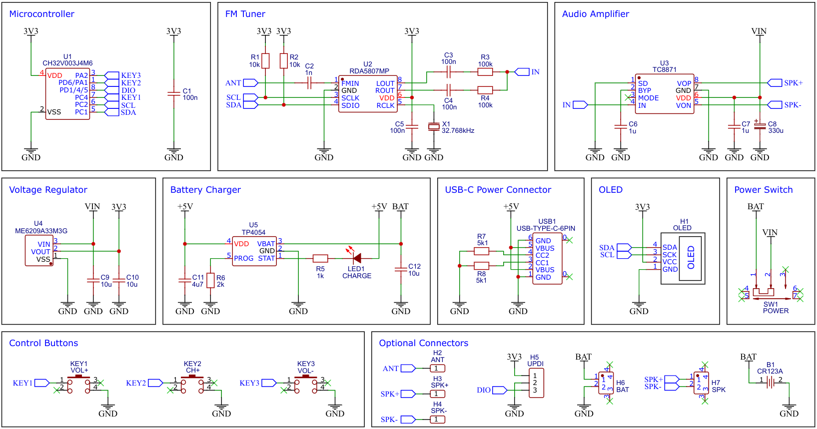
The CH32V003 Family of 32-bit RISC-V Microcontrollers
The CH32V003 series is a collection of industrial-grade general-purpose microcontrollers that utilize the QingKe RISC-V2A core design supporting the RV32EC instruction set. These microcontrollers are equipped with various features such as a 48MHz system main frequency, 16KB flash, 2KB SRAM, wide voltage support, a single-wire serial debug interface, low power consumption, and an ultra-small package. Additionally, the CH32V003 series includes a built-in set of components including a DMA controller, a 10-bit ADC, op-amp comparators, multiple timers, and standard communication interfaces such as USART, I2C, and SPI.
RDA5807MP FM Radio Tuner IC
The low-cost RDA5807MP is a single-chip broadcast FM stereo radio tuner with fully integrated synthesizer, IF selectivity, RDS/RBDS, and MPX decoder. The tuner uses the CMOS process, support multi-interface, and require the least external component. All these make it very suitable for portable devices. The RDA5807MP is controlled by the microcontroller via I²C.
TC8871 Audio Amplifier IC
The TC8871 is an FM-free, Class AB/Class D selectable power amplifier. When the working voltage is 5V, the maximum driving power is 5W (2Ω, BTL load, THD>10%). The application circuit of TC8871 is simple, only a few peripheral devices are needed, and the feedback resistor is integrated; the output does not need an external coupling capacitor or a power-up capacity and buffer network.
The amplification can be selected via the value of the resistors R3 and R4 (Gain = 2 100kΩ / (10kΩ + R3), R4 respectively), which determines the maximum volume. Keep in mind that the resistors together with the coupling capacitors C3 and C4 form a high-pass filter whose cut-off frequency is determined using the following formula: f = 1 / (2 π R3 C3), R4 and C4 respectively.
TP4054 Li-Ion Battery Charge IC
For battery charging the TP4054 is used. The TP4054 is a complete constant-current/constant-voltage linear charger for single cell lithium-ion batteries. Its small package and low external component count make the TP4054 ideally suited for portable applications. The constant current value is set with one external resistor (I = 1000V / R6). Charging is done via the built-in USB-C connector. The TP4054 can be replaced by a MCP73831.
ME6209A33 3.3V Linear Voltage Regulator
The ME6209 series are a group of positive voltage output, three–pin regulator, that provide a high current (max 250mA) even when the input/output voltage differential is small (80mV dropout voltage). Low power consumption (3µA quiescent current) and high accuracy (+/-2%) is achieved through CMOS technology. They allow input voltages as high as 18V.
Building Instructions
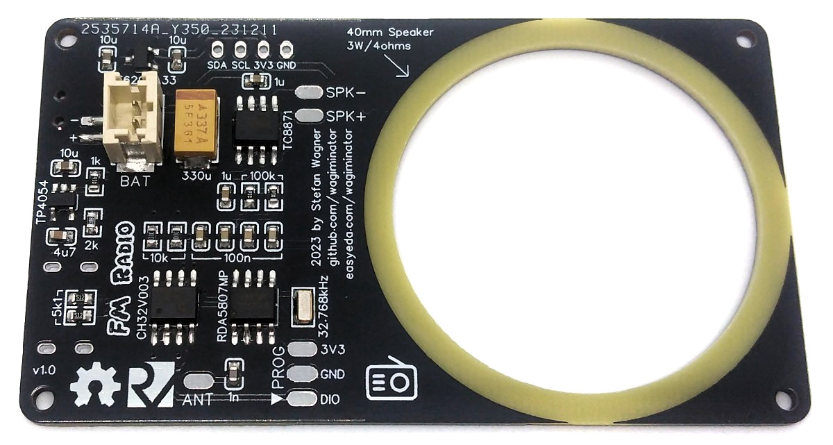
Solder all components to the PCB. Place the 40mm speaker in the corresponding cutout on the board. Glue the speaker in place with hot glue. Make sure that the glue is airtight all around to achieve good sound quality. Solder the connection cables between speaker and board. Solder the wire antenna to the corresponding pad on the board. A 75cm (30" = λ / 4) long 28AWG flexible silicone insulated wire works very well.
3D print the case. Cases with different heights are available in the "3dprint" folder. Choose the case that matches the height of your battery and speaker. Glue the battery into the case with double-sided tape. Thread the wire antenna through the small hole in the housing. To improve the sound quality, you can pack a foam mat between the battery and the PCB inside the case. This should fit snugly against the outer walls of the housing.
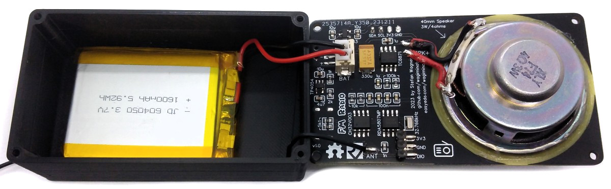
Connect the battery to the JST connector on the board. Pay attention to the correct polarity, unfortunately there is no standard here! At the latest now you should upload the firmware (see below). Use the PROG pads on the board for this. Place the board on the case and screw it with four M2x5mm self-tapping screws.
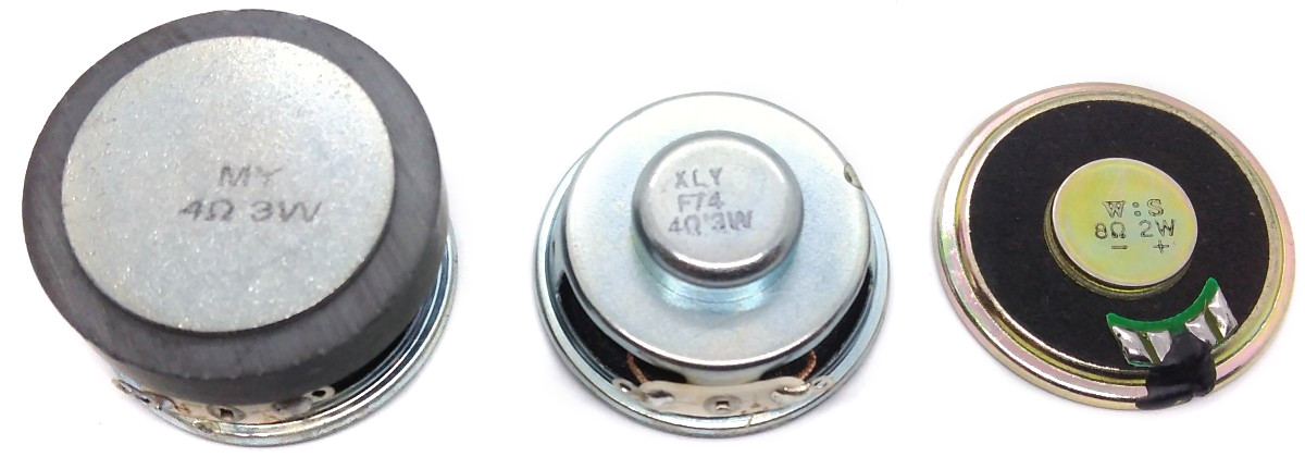
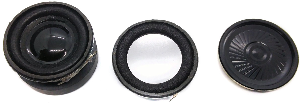
There are different loudspeakers with 40mm diameter. The flatter ones allow the radio to be built more compactly, while the taller ones have better sound quality.
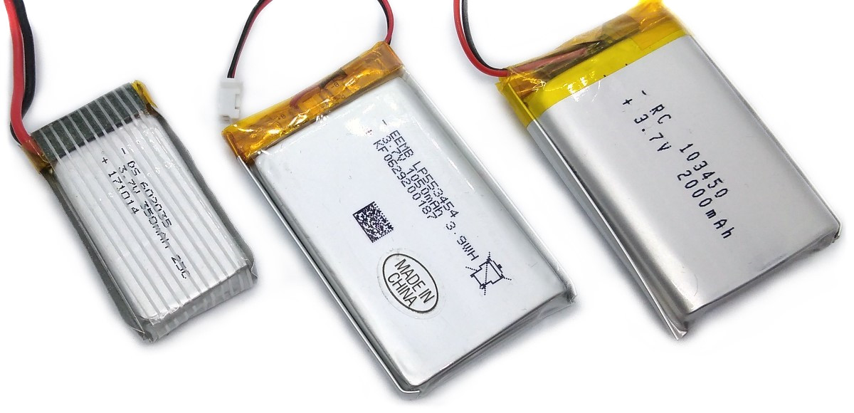
The size of the battery also affects the size of the radio. In operation, the radio consumes around 100mA - 125mA at 3.7V and medium volume. So a battery with a capacity of 1200mAh should provide around 10 hours of playtime.
Software
Controlling the RDA5807
The FM tuner IC RDA5807MP is controlled via I²C by the microcontroller. It has six writable 16-bit registers (addresses 0x02 - 0x07) and six readable 16-bit registers (addresses 0x0A - 0x0F). The RDA5807 has two methods of write access, a sequential one in which the registers are always written starting from address 0x02 and an indexed method in which the register address is transferred first and then the content. Both methods are determined by different I²C addresses. To transfer the 16-bit register content, the high byte is sent first. The RDA5807 is controlled by setting or clearing certain bits in the respective registers. The details of the meanings of the individual registers can be found in the data sheet. The current register contents are saved in the RDA_regs arrays. The RDA implementation is based on the work of Maarten Janssen.
Programming and Debugging Device
To program the CH32V003 microcontroller, you will need a special programming device which utilizes the proprietary single-wire serial debug interface (SDI). The WCH-LinkE (pay attention to the "E" in the name) is a suitable device for this purpose and can be purchased commercially for around $4. This debugging tool is not only compatible with the CH32V003 but also with other WCH RISC-V and ARM-based microcontrollers.
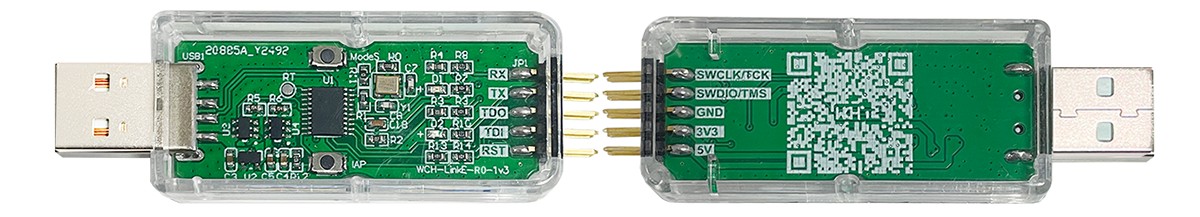
To upload the firmware, you need to ensure that the FM Receiver is switched off or the battery is removed. Then, you should make the following connections to the WCH-LinkE:
WCH-LinkE     FM Receiver
+-------+      +-------+
|  SWDIO| <--> |DIO    |
|    GND| ---> |GND    |
|    3V3| ---> |3V3    |
+-------+      +-------+
If the blue LED on the WCH-LinkE remains illuminated once it is connected to the USB port, it means that the device is currently in ARM mode and must be switched to RISC-V mode initially. There are a few ways to accomplish this:
- You can utilize the Python tool rvprog.py (with -v option), which is provided in the software/tools folder.
- Alternatively, you can select "WCH-LinkRV" in the software provided by WCH, such as MounRiver Studio or WCH-LinkUtility.
- Another option is to hold down the ModeS button on the device while plugging it into the USB port.
More information can be found in the WCH-Link User Manual.
Compiling and Uploading Firmware (Linux)
To use the WCH-LinkE on Linux, you need to grant access permissions beforehand by executing the following commands:
echo 'SUBSYSTEM=="usb", ATTR{idVendor}=="1a86", ATTR{idProduct}=="8010", MODE="666"' | sudo tee /etc/udev/rules.d/99-WCH-LinkE.rules
echo 'SUBSYSTEM=="usb", ATTR{idVendor}=="1a86", ATTR{idProduct}=="8012", MODE="666"' | sudo tee -a /etc/udev/rules.d/99-WCH-LinkE.rules
sudo udevadm control --reload-rules
Install the toolchain (GCC compiler, Python3, and PyUSB):
sudo apt install build-essential libnewlib-dev gcc-riscv64-unknown-elf
sudo apt install python3 python3-pip
python3 -m pip install pyusb
Switch off the FM Receiver or remove the battery. Connect the FM Transmitter via the 3-pin PROG header to the WCH-LinkE programming device. Open a terminal and navigate to the folder with the makefile. Run the following command to compile and upload:
make flash
If you want to just upload the pre-compiled binary, run the following command instead:
python3 ./tools/rvprog.py -f fm_radio.bin
Uploading Firmware Binary (Windows/Mac)
WCH offers the free but closed-source software WCH-LinkUtility to upload the precompiled hex-file with Windows. Select the "WCH-LinkRV" mode in the software, open the fm_radio.hex file and upload it to the microcontroller.
Alternatively, there is a platform-independent open-source tool called minichlink developed by Charles Lohr (CNLohr), which can be found here. It can be used with Windows, Linux and Mac.
If you have installed Python3 and pyusb on your system, you can also use the included Python tool rvprog.py:
python3 ./tools/rvprog.py -f fm_radio.bin
Operating Instructions
- Make sure that the wire antenna is laid as straight as possible horizontally or vertically.
- Turn on the radio using the power switch.
- Use the volume buttons to select the volume from 0 to 15.
- The next station is searched for with the "CH+" button.
- When the OLED shows "Bat: weak", you should soon recharge the battery via the USB-C port.
If there's no radio station nearby and/or you want to build one yourself, take a look here.
References, Links and Notes
- EasyEDA Design Files
- CNLohr: ch32003fun
- WCH: CH32V003 datasheets
- WCH: WCH-Link user manual
- WCH: Official Store on AliExpress
- RDA5807MP Datasheet
- TC8871 Datasheet
- TP4054 datasheet
- ME6209 Datasheet
- SSD1306 Datasheet
- ATtiny13A TinyPocketRadio
- ATtiny85 TinyFMRadio
- ATtiny412 FM Pocket Radio
- CH32V003 FM Radio Transmitter
- 128x64 OLED on Aliexpress
Schematics, diagrams and documents
CAD, enclosures and custom parts
Code
Credits
Related products


Leave your feedback...