
Visuino Display Live Forex Currency Price From Internet

Made by Ron / Displays / Notifications / IoT
About the project
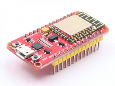
Use a NodeMCU Mini, an OLED, and Visuino to display real-time EUR/USD currency prices every few seconds from the Internet.
Items used in this project
Hardware components

Software apps and online services
Story
In this tutorial, we will use a NodeMCU Mini from Makerfabs, an OLED, and Visuino to display real-time EUR/USD currency prices every few seconds from the Internet.
Step 1: What You Will Need
1 / 3
All the modules are from Makerfabs. They have the best quality modules that are lightyears ahead of the competition, also with best affordable prices.
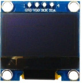
- OLED display
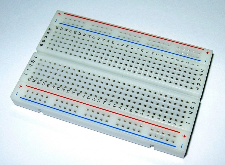
- Breadboard
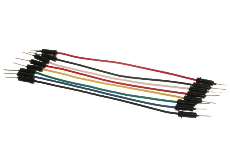
- Jumper wires
- Visuino program (Download)

- Connect GND from NodeMCU to breadboard pin (gnd)
- Connect 5V pin from NodeMCU to breadboard pin (positive)
- Connect pin 0 (SCL) from NodeMCU to OLED LCD pin (SCL)
- Connect pin 1 (SDA) from NodeMCU to OLED LCD pin (SDA)
- Connect OLED LCD pin (VCC) to breadboard pin (positive)
- Connect OLED LCD pin (GND) to breadboard pin (GND)
1 / 2
To start programming the Arduino, you will need to have the Arduino IDE installed from here.
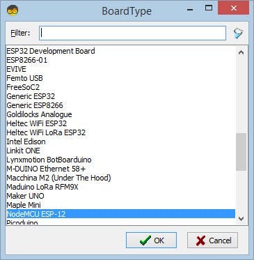
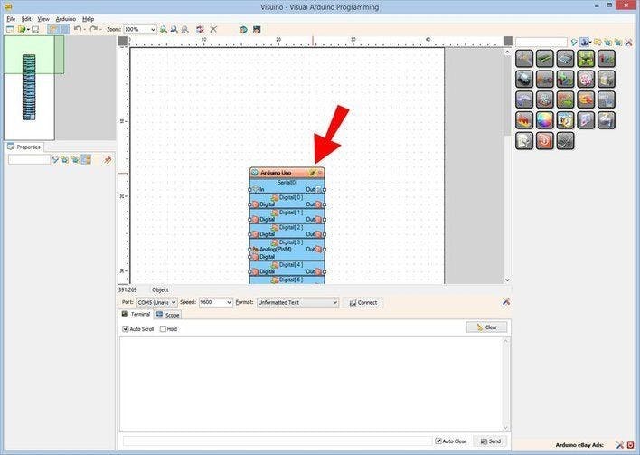
Please be aware that there are some critical bugs in Arduino IDE 1.6.6. Make sure that you install 1.6.7 or higher, otherwise this tutorial will not work! If you have not done follow the steps in this tutorial to setup the Arduino IDE to program ESP 8266! The Visuino also needs to be installed. Start Visuino as shown in the first picture Click on the "Tools" button on the Arduino component (Picture 1) in Visuino When the dialog appears, select "NodeMCU ESP-12" as shown on Picture 2
Step 4: WiFi Setup
1 / 6
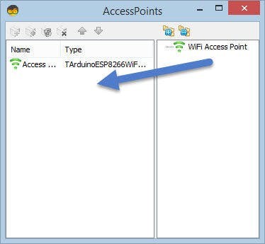
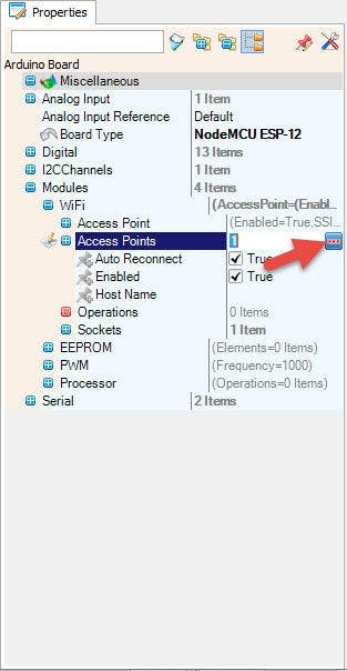
- Select NodeMCU ESP-12 and in the editor Modules>WiFi>Access Points, click on [...] button, so that "Access points " window will open.
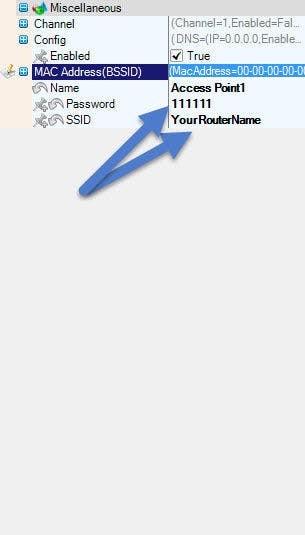
In this editor drag the WiFi access point to the left side.
- Under "SSID" put the name of your WiFi Network
- Under "Password" put the access password for your WiFi network
Close the "Access points" window.
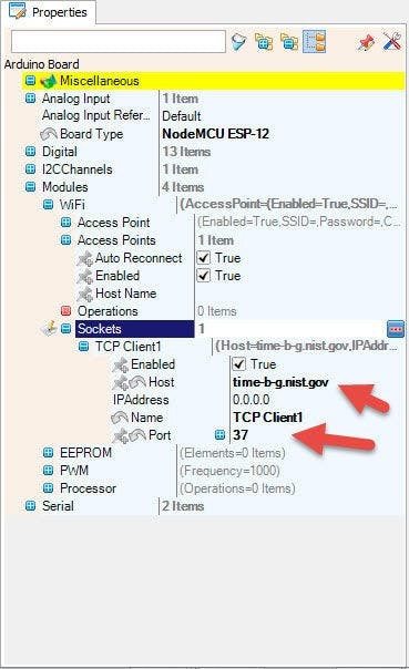
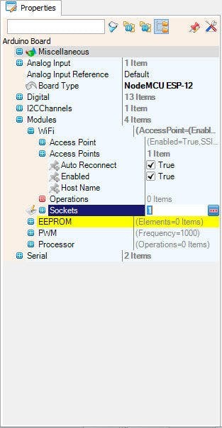
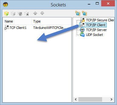
On the left in editor select Modules>Wifi>Sockets, click on [...] button, so that "Sockets" window will open.
Drag the TCP Client from right to the left side.
Under Properties window set port: 80
Step 5: Add Components in Visuino
1 / 7
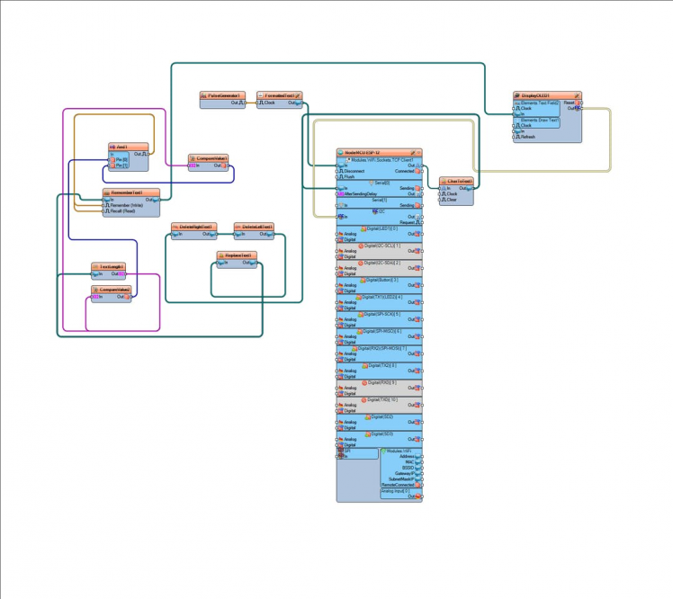

- Add "And" logic component
- Add "Remember Text" component
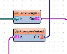
- Add "Text Length" component
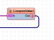
- Add 2x "Compare Value" component
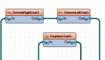
- Add "Delete Right Text" component
- Add "Delete Left Text" component
- Add "Replace Text" component
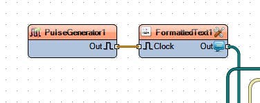
- Add "Pulse Generator" component
- Add "Formatted Text" component
- Add "Char To Text" component
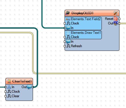
- Add "Display OLED" I2C component

- Connect "And1" pin [Out] to RememberText1 pin [Remember] and pin [Recall]
- Connect "And1" pin [0] to "CompareValue2" pin [Out]
- Connect "And1" pin [1] to "CompareValue1" pin [Out]
- Connect TextLength1 pin [Out] to CompareValue1 pin [In] and CompareValue2 pin [In]
- Connect "DeleteRightText1" pin [In] to CharToText1 pin [Out]
- also connect CharToText1 pin [Out] to NodeMCU serial[0] pin [In]
- Connect "DeleteRightText1" pin [Out] to DeleteLeftText1 pin [In]
- Connect DeleteLeftText1 pin [Out] to ReplaceText1 pin [In]
- Connect ReplaceText1 pin [Out] to RememberText1 pin [In]
- Connect RememberText1 pin [Out] to DisplayOLED1 > Text Field >pin [in]
- Connect DisplayOLED1 pin [Out] to NodeMCU ESP-12 I2C pin [In]
- Connect PulseGenerator1 pin [Out] to FormattedText1 pin [Clock]
- Connect FormattedText1 pin [Out] to NodeMCU ESP-12 > Modules WiFi Sockets TCP Client1> Pin[In]
- Connect NodeMCU ESP-12 > Modules WiFi Sockets TCP Client1> Pin[Out] to CharToText1 pin [In]
1 / 2
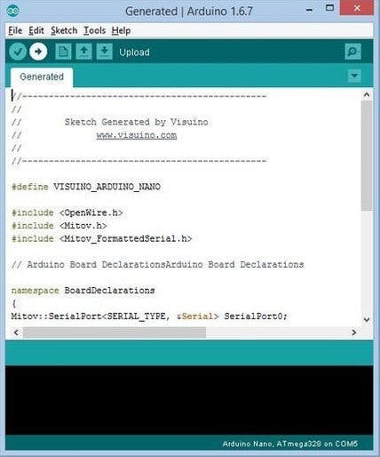
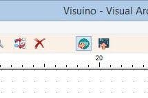
In Visuino, press F9 or click on the button shown on Picture 1 to generate the Arduino code, and open the Arduino IDE.
In the Arduino IDE, click on the Upload button, to compile and upload the code (Picture 2)
Step 8: PlayIf you power the NodeMCU module, the OLED Lcd will start showing the current price of EUR/USD.
Congratulations! You have completed your Live Forex Price project with Visuino. Also attached is the Visuino project, that I created for this tutorial. You can download and open it in Visuino: Download link All the modules can be bought at https://www.makerfabs.com
Step 9: Component Settings in Visuino
- CompareValue1: In property editor set "Value":3, and Only Changed:True, and "CompareType":ctBigger
- CompareValue2: In property editor set "Value":8, and Only Changed:False, and "CompareType":ctSmaller
- DeleteRightText1 in property editor set "Length":931
- DeleteLeftText1 in property editor set "Length":53
- ReplaceText1 in property editor set "From Value": </td><td>
- PulseGenerator1 in property editor set "Frequency":1
- CharToText1 in property editor set "Max Length":1000, and "Truncate": False, and "Update on each char":False
- DisplayOLED1 > Double click>
- in editor drag "Text Field" to the left and set in properties window "Size":2, and "Y":50
- in editor drag "Draw Text" to the left and set in properties window "Text":EUR/USD, and "Size":2
- FormattedText1 in property editor under "Text" click "..." and add this text:
GET http://webrates.truefx.com/rates/connect.html?f=h... HTTP/1.1Accept: text/html
Accept-Charset: utf-8
Accept-Language: en-US,en;q=0.7,sl;q=0.3
Host: webrates.truefx.com
DNT: 1
Credits
Related products


Leave your feedback...