
Vintage Bench-Top DC Hybrid Voltmeter

Made by electrouser805
About the project
With a DC range of -25V to +25V, a voltmeter combining analog needle & digital LEDs to represent integer & fractional voltages respectively.
Project info
Difficulty: Easy
Platforms: Arduino, SparkFun, Texas Instruments
Estimated time: 1 hour
License: GNU General Public License, version 3 or later (GPL3+)
Items used in this project
Hardware components


View all

Story
Intro
Once upon a time before the digital era, voltmeters were made with springs, needle pointer, EM coils and burden loads. Nowadays, many kids don't know what those looked like!
This is the story of an analog-looking hybrid voltmeter using digital stuff!
Don't wanna read ? Watch then ......
vmm in actionFeatures
- Capable of measuring voltage drop across any resistor in live circuit
- Measure negative voltage
- Active range -25 volts DC to +25 volts DC
- Accuracy of +/- 0.1 volts for voltage source
- Accuracy of 90% for voltage drop measured across resistor
- Improved ADC noise reduction
- Battery powered
- Artwork for desktop
- High input resistance voltage divider
- Floating ground is buffered to source/sink current
Build
The enclosure is made from old desktop calendar. The needle movement is done by servo motor and decimal is presented by 10 LEDs. An appropriate sized slit and a hole is made on the inner walls of the calendar and the servo motor and LEDs are hot glue mounted.
 1 / 3 • Preparing Desktop Calendar for Enclosure
It can measure from negative 25 to positive 25 volts with a resolution of 0.1 volts. The dial is made in MSWord using wordArt, the screenshot us transferred to Paint, inverted to get the dial. Next printed on photo paper with Inkjet printer.
Next, the control circuit is built on a breadboard, the breadboard is placed inside the calender's cleavage.
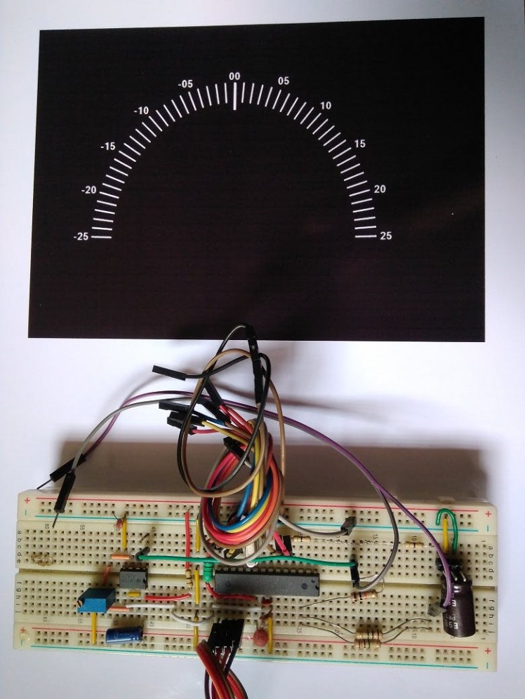 Circuit and the printed dial
Finally, the dial is cut from the photo paper and using gum, it is placed on the front side.
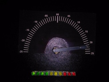
 Voltmeter Display
Program
Programming can be done in two ways. The program is written in Arduino IDE.
Method 1
Removing the actual Atmega328P from Arduino UNO board and then placing the new Atmega328P with Arduino bootloader in it. Then uploading the sketch provided, then removing the chip back to breadboard.
Method 2
Using a USB to FTDI (Serial) Module. In this method the module upload the code over serial to the bootloaded UNO chip.
Tutorial here.
Application
This is not a replacement of regular voltmeter. It is mainly useful when multiple voltages are required to be monitored at once.
It can measure voltage difference/ drop across a resistor but there is a problem known as loading effect. An 500k by 10k resistor voltage divider network is used to attenuate larger voltages to fit ADC range (0 to 1.1 volts). This resistor divider is in parallel to the external circuit and can change the actual voltage by loading it.
More on loading effects from AllAboutCircuits.
Watch this nice video on EEVBLOG about this.
Basically it's best for measuring power supply voltages, battery voltages and voltage drop across smaller (few K) resistors.
Negative Voltage Measurement Explained!
The negative voltage measurement is done with the help of a generic Opamp and some passives using a trick.
There is a function in Arduino called analogReference(INTERNAL); which will put a constant 1.1 V ( may vary from between 1.06 to 1.13 from chip to chip) on AREF pin of Uno/ATmega328P . Once this function is called all ADC conversion will happen between Gnd and AREF Volt rail.
Gnd to AREF or Gnd to Vcc range ADC conversion is known as Single ended Conversion, which requires that there the ADC measurement is done with respect to common ground ( Arduino ground ). This is not suitable for Negative Voltage Measurement.
The trick is to use one of the two points between which the voltage is measured of any external circuit ( could be one terminal of a battery or one point of a resistor) connected to 1/2 of AREF voltage. This way the other point's potential could be either greater ( in case of + ) or less ( in case of -- ) than this 1/2 AREF point, so a difference between two points can be measured.
The AREF pin can't drive load ( i.e. a voltage divider resistor ). So, this voltage is buffered with an Opamp. Buffering means, forwarding the same signal/voltage with more current driving capability and protecting the incoming signal from getting overloaded/reduced. Then the buffered output is voltage divided using variable resistor to get 1/2 AREF voltage ( in this case 0.544 V ). This half voltage is buffered again with another Opamp, Then the second buffered voltage is connected to one point of the external circuit. The other point is also connected to the external voltage. Between these two points there is voltage divider to scale down the measurement voltage. The mid point of the divider is sampled by the Arduino ADC.
The circuit looks like this -
'
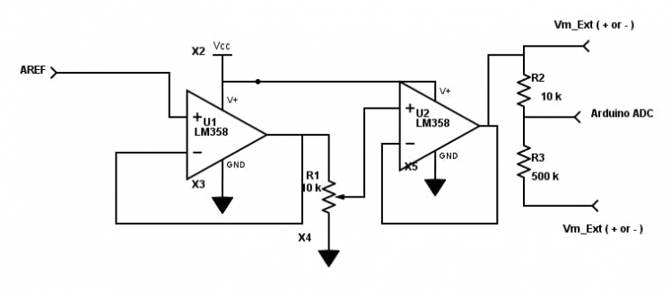 Signal Conditioning for ADC
This method has two disadvantage :
- ADC resolution drops 1 MSB, which means 10 bit ADC will become 9 bit.
- Any voltage measured on the internal circuit is not possible using that ADC pin
Schematics, diagrams and documents
Code
Credits
Related products


Leave your feedback...