

Trundlebot - The Educational Robot

Made by alistair / Kids & Family / Robotics
About the project
This fun “turtle” robot is a low cost education toy that anyone can build and enjoy learning to programme with.
Project info
Difficulty: Moderate
Platforms: MicroPython, Python
Estimated time: 2 hours
License: Creative Commons Attribution-NonCommercial CC BY-NC version 4.0 or later (CC BY-NC 4+)
Items used in this project
Hardware components


View all
Hand tools and fabrication machines
Story
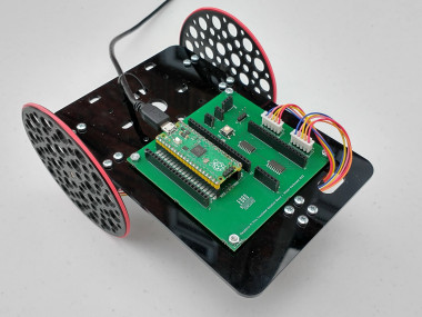
Trundlebot Overview
This is a project to create a simple low cost “turtle” like robot that anyone can own and use to learn to program with. It is based around the Raspberry Pi Pico and makes learning to programme more fun.
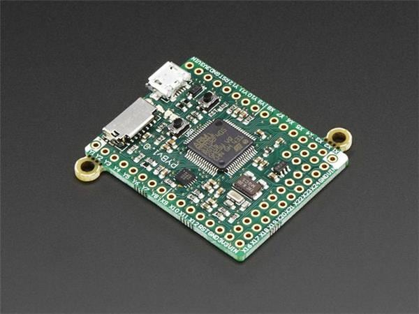
The design is compatible with Raspberry Pi Pico, Raspberry Pi Pico W, W5100S-EVB-Pico and WIZnet WizFi360.
The Trundelbot is designed to be easy to build, easy to modify and expand, affordable to everyone, and fun to play with.
This guide is designed to be accessible. The schematics and technical documents are available below if you are more technically minded.
Assembling the PCB board
You need to have a Trundlebot PCB that can be ordered online. All the details a manufacturer needs are in the “Trundlebot KiCad PCB File” and the “Trundlebot BOM File” below. Thank you to Eurocircuites for making the prototype boards.
Most of the components will have been assembled by the board manufacturer, but we still need to add some connectors. This is not hard to do and is good practice if you are new to soldering. Don’t worry, it is really really hard to break, and there are many really good tutorials online if you have not done it before.
First let's get all the parts we need for this.
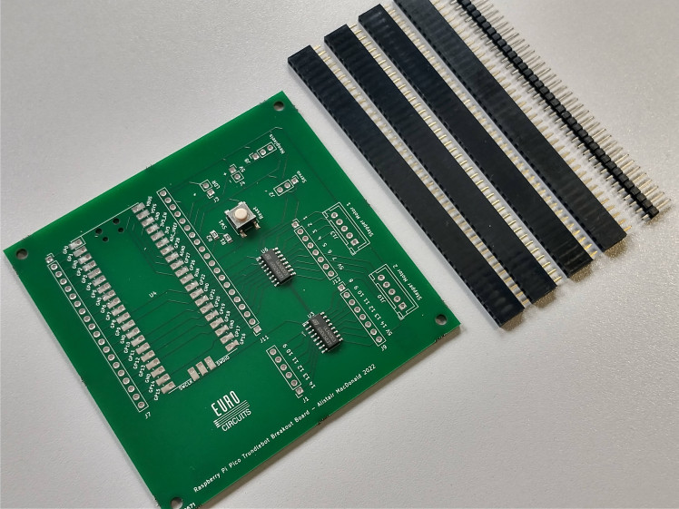
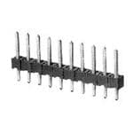
You will need the Trundlebot PCB, four 40-pin 2.54 mm pitch header socket strips, and a 40-pin 2.54 mm pitch header pin strip.
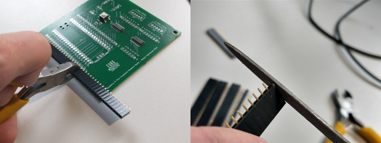
Now let's cut the headers into the lengths required. You will need 4 x 20 socket, 2 x 8 socket, 1 x 6 socket, 1 x 3 socket, and 2 x 2 socket. You will also need 2 X 5 pin header for the stepper motors and a single 3 pin header for the stepper motor.
There are a couple of tricks you can use to make soldering the connectors easier. First is to use some header pins to hold the Pi Pico header sockets in place. Having some blue/Blu/white tack to hold the headers in place will also make things easier for the other connectors.
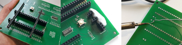
Finally when soldering long strips of headers it is good practice to solder the pins at either end, check they are straight, and solder all the pins in between.
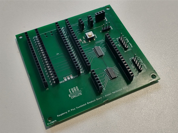
You should have something that looks like this when you are done.
Now on to the rest of the hardware.
Assembling the Trundlebot
First gather all the parts you need.
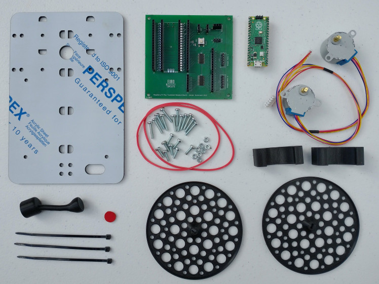
- The assembled Trundlebot PCB from above
- Raspberry Pi Pico or compatible
- 2 X 28BYJ stepper motors
- 3D printed parts (2 X “Wheel”, 2 X “Motor Holder” and “Trundlepad” from the files below)
- 2 X Rubber bands
- 20 X M3 screws (8 X 10mm and 12 X 16mm, although 20 X 12mm will suffice)
- 8 X M3 nuts
- A Trundlebot chassis (Laser cut from the “Chassis” file below)
- Felt pad (either a self adhesive "Glider" or felt cut to size)
- A cables tie
Before we start adding things to the chassis there are a few parts that are easy to assemble first. First are the wheels.
The wheels require a rubber band to be placed around the circumference to give the Trundlebot more grip. The easy way to do this is to place the wheel flat on a table and hold the band with two fingers along one side. Then pull the other side down, wrap it round, and then slowly let it draw in.
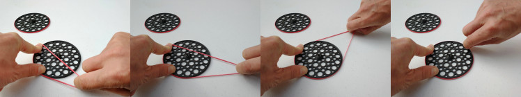
The bands will occasionally fall off, but if this happens frequently then they are probably too tight and you should try some larger ones. Flat rubber bands tend to be more reliable than square or round ones.
Next let's prepare the trundlepad. Stick on your felt or Glider. An offcut of felt stuck with Gorilla Glue Clear is photographed here. Be careful not to get the glue on the surface of the felt.
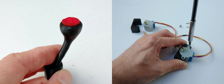
Next we need to attach the motors to the motor mounts. Simply place in the slot with the wires pointing away from the flat surface and screw in the shorter 10mm screws. The motor should not move, but be careful not to over tighten.
Now we need to attach everything to the chassis. First place a 10mm screw through a hole on the chassis for the PCB. You can hold the PCB over the chassis to confirm you have the right holes. Screw on a nut and tighten with your fingers, and then repeat for the other 3 holes. The side with the nut on is now the top of the Trundlebot.
Next screw on the motor mounts to the bottom of the chassis. Again, do not over tighten the screws. Do the same with the trundlepad. Check the following photo if you are not certain about the direction.
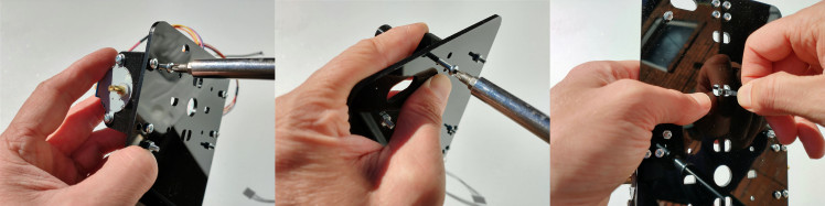
To finish off this step push a cable tie though the second set of slots from the trundlepad end secure the cables. You can also push the motor connectors though the pill shaped hole.
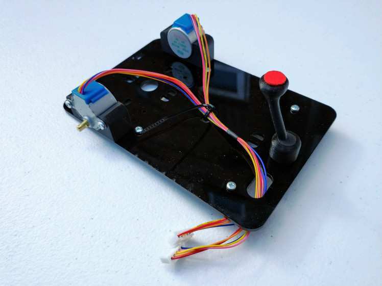
You should now have something that looks like this. You can cut off the excess cable tie.
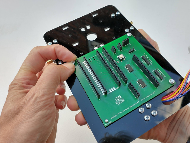
Now we can add the Trundlebot PCB we assembled before. Simply place over the screws in the orientation photographed. Screw on the remaining nuts and tighten fingertight. Connect the left stepper motor (the side of the connectors) to “Stepper Motor 1” and the right motor to “Stepper Motor 2”. The red wire should be to the bottom / front of the board.
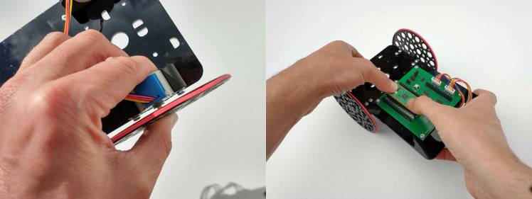
We are almost done. Now slowly but firmly push on the wheels until they will not push on any further. Finally insert your Pi Pico with the USB connector facing the top/back.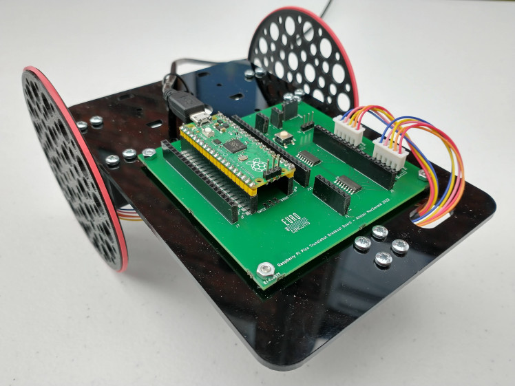
Well done, you now have built your Trundlebot. Now let's get it doing something.
Uploading the software
The easiest way to programme the Trundlebot us to use the Thonny software. Instructions to get this installed and working with the Raspberry Pi Pico is on the Raspberry Pi web site ( https://projects.raspberrypi.org/en/projects/getting-started-with-the-pico ) . Please follow these instructions until you have completed the “Blink the onboard LED” section.
To use the Trundlebot motors we first need to upload the “trundle” library. First download the library to your computer from https://raw.githubusercontent.com/alistairuk/trundlebot/main/lib/trundle.py (right clicking and “Save link as…” should do that).
Next open Thonny, select "File", then “Open…”, and then click the "This Computer" button. If the button is not shown then Thonny is not configured correctly for the Pi Pico and you should go back to the Raspberry Pi instructions. Then select the file you downloaded.
There are two settings that can now be changed. Most hardware will work fine with the default settings. You will see a line that reads “wheel_diamiter = 99”. If you use a thick rubber band you may need to increase this value to 100. The setting “wheel_separation = 138” is the distance between the middle of the rubber bands and will normally be correct.
Now we can save it to the Pi Pico by selecting "File" again, then "Save Copy...", this time clicking the "Raspberry Pi Pico" button, and entering the filename "trundle.py".
That is the library installed. It can be tested in the Thonny “shell” tab at the bottom of the window. First enter the line…
- import trundle
This will tell the Pi Pico to use the Trundle library. Next try…
- trundle.forward(40)
This should make the Trundlebot move forward 40mm. If not then check the troubleshooting section below.
Now let's have some fun with writing some code.
Programming the Trundlebot
You can programme the Trundlebot using Micropython. If you are new to this then I suggest continuing with the examples on the raspberry Pi site linked above. To move the Trundlebot we have four commands in the trundle library. Forward, Back, Left and Right. Here are some examples.
- # Include this at the top of every programme
- import trundle
- # Move forward 50mm
- trundle.forward(50)
- # Move back 20mm
- trundle.back(20)
- # Turn right 45 degrees
- trundle.right(45)
- # Turn right 90 degrees
- trundle.left(90)
A fun first challenge is to create an obstacle course and programme your Trundlebot to drive through it. Here is us having a go...
Yes, we are rubbish at it. You will do much better.
If you like the cones then the design is also available for download below. Drawing a track on a large sheet of cardboard or using household items on a table will work just as well.
There are a number of other examples at https://github.com/alistairuk/trundlebot/tree/main/examples to get you going.
Troubleshooting
If you have any problems then hopefully we have the solution here.
- The Trundlebot does not move at all.
The most likely reason for this is the stepper motor connectors are connected the wrong way round. The red wire should be at the bottom/front of the board.
- The Trundlebot turns the wrong way
The stepper motor connectors are plugged into the wrong sockets, swap over the two and it should now turn the correct way.
- The Trundlebot is not travelling the correct distance
The “wheel_diamiter” setting may need to be tweaked for your Trundlebot. See how to do this in the Uploading the software section above. If the Trundlebot does not move far enough then reduce the value. If it moves too far then increase this value.
- The Trundlebot is not turning to the correct angle
First check the wheel_diamiter is correct as this setting also affects the angle. If so then tweak the “wheel_separation” until the turn is correct. If it does not turn enough then reduce the value. If it overturns then increase the value.
Expanding and Modding
The Trundlebot is supposed to be an infinitely extendable system and does not dictate what you have to do. Anything you can do with a Raspberry Pi Pico can be done with a Trundebot, but with wheels on, and that makes it cooler.
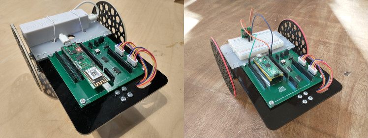
Here are a couple of examples I am working on. First is a battery adapter that allows the Trundelbot to be controlled over Wifi. Second is a small transmitter to allow the Trundlebot to turn on and off smart sockets as it moves.
If you want to add your own extensions to the Trundlebot then the Trundlebot Expansion Plate design can be downloaded from below. The expansion plate simply slots over the screws to hold your project in place.
Final Notes
If you would be interested in buying a circuit board or 3D printed parts kit then leave a comment here. If there is enough interest then I will look at creating a not-for-profit marketplace or crowdsource project to make them available to all.
Also thank you to Eurocircuits for supporting this project. Thanks to them I have a few boards to give away to after school projects. Again comment below if you are interested in one.
Schematics, diagrams and documents
CAD, enclosures and custom parts
Code
Credits
Related products


Leave your feedback...