
Sony DIY Retro MP3 Player

Made by electrouser805 / Music
About the project
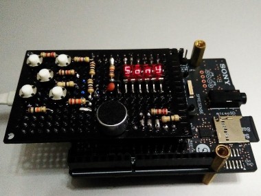
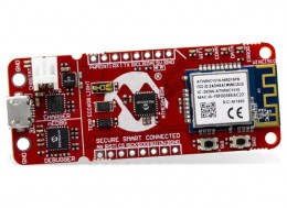
A plain vanilla MP3 player build with Sony Spresense board which has a display + 5 buttons for controlling volume/play/pause/changing songs.
Project info
Difficulty: Moderate
Estimated time: 1 hour
License: Creative Commons Attribution-NoDerivs CC BY-ND version 4.0 or later (CC BY-ND 4+)
Items used in this project
Hardware components
View all

Story
About
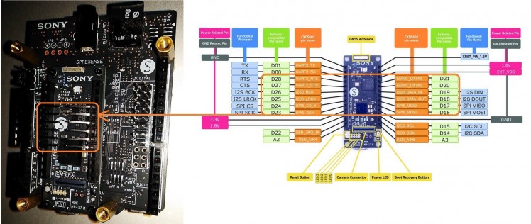
This is an MP3 player with user control buttons and display based on Sony Spresense board. It utilized the extra GPIOs (D16-D28 and A3) on the main board for user interface. There is also a microphone for recorder function.
The benefit of this design is that, it lefts all the I/O pins on the outer rows available for further development of complex project and still use the Sony Spresense as a music player.
Features
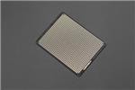
- Bubble display UI
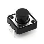
- 5 buttons for user Input
- Play/stop, volume up/down, prev/next song selection
- 50 step volume control (-20dB step)
Following video demonstrates the functions :
My speaker is broken, so it's tested with headphoneHardware
The UI Shield: 5 buttons, 1 mic, 7-segment display
First, a 6x4 cm double sided protoboard is darkened with Black permanent marker for matching colors with the main/extension board.
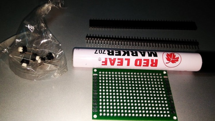 Coloring black and adding headers
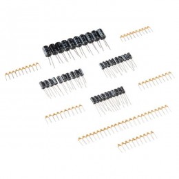
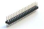
Next, male and female headers are placed on the sony spresense board for bringing out D16 to D28 I/O pins, Gnd, 1.8V, A3 and Analog MIC A on the blacked protoboard. The protoboard is placed on the headers connected to the main board and soldered.
The protoboard is positioned in such a way, that it does not cover the GPS antenna (for future project).
 Top side soldered
Then, the protoboard is unplugged from the Sony Spresense board for soldering the seven segment 4 digit display, 5 user switches and a mic.
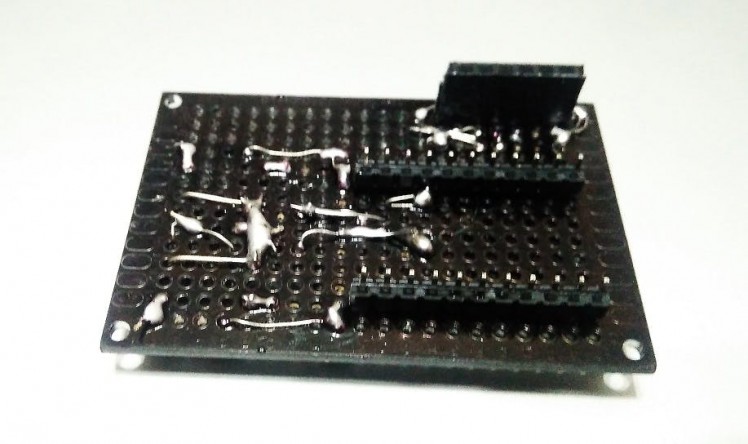 Bottom side Soldered
After soldering all the components, it's plugged again on the main board with proper alignments.
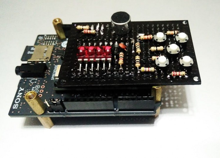 UI shield mounted on Sony spresense board
Warning!
The main boards I/O pins are 1.8 volts, as the bubble display operates between 1.6-2.0 volts, all the segment/digit pins are directly connected to the I/O pins of main board through male header.
 12 GPIO pins D16-D28 (except D22) for the display (see code for pinmap)
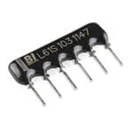
All the user buttons are connected to ADC A3 on main board through 1k/2.2k/4.7k/10k/22k resistors. A3 has a 10k pulldown (this is on board resistor) resistor on it.
Main board ADC has a full scale voltage of 0.0 to 0.7 volts for reading 0 to 1023. Pressing on each button creates a different voltage level on A3 due to these voltage divider combinations (e.g 1k||10k or 2.2k||10k or 4.7k ||10k ). That's how which button is pressed is registered and associated functions are executed.
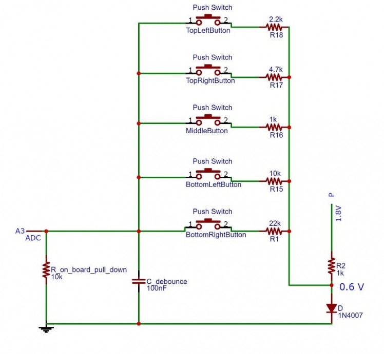 ADC Switch Sensing
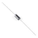
To get a safe 0 to 0.7 volts range, a silicon diode with 1k is connected between 1.8 V and Gnd. One end of 1k/2.2k/4.7k/10k/22k each resistors, connects to the anode of the diode, other end goes to the ADC through 5 of those push switches. (see schematic above)
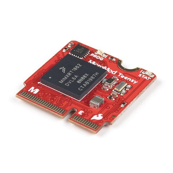
Sony Spresense main + Extension boards
The UI shield sits on the main board and the main board sits on the extension board. Extension board allows SD card support and audio input/output capabilities.
Besides all the Uno R3 equivalent I/O pins on the extension boards are available for future projects without undoing the MP3 player hardware.
Programming
The core functionalities are based on SDHCI and Audio library for the sony spresense boards example code.
API details can be found here.
Required Additional Stuff
- Micro SD card with MP3 songs (formatted in FATex)
- Headphone/speaker (32 ohms/8ohms)
- USB/5V power supply (500mA)
- USB data cable (2.0)
- Renaming of MP3 files as 1.mp3, 2.mp3, 3.mp3 etc.
- Copying encoder/decoder bin files to SD card
- Spresense Board Library version 1.1.3
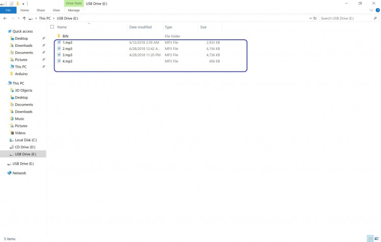 MP3 renaming
Caveats & Conclusion
Right now play/stop, song prev/next and volume up/down functions are working. Rest of the features will be added later.
- There is a "3 second play and stop bug" when USB mass storage option is enabled from code, thus disabled.
- mp3 bit rate should be 192 kbps. Lower bit rate gives faster tempo
- ADC switch may rarely give wrong operations (during transition).
- Songs closing/loading takes about 2 seconds of file operation.
- MP3 files are required to rename 1.mp3, 2.mp3, 3.mp3 and so on.
- There is mic for recording but recorder function is not added yet on code.
This is not a replacement for commercial solutions but a good starting point for audio control projects like annunciation system, talking voltmeter, etc.
Schematics, diagrams and documents
Code
Credits
Related products

Leave your feedback...