
Solid State Protection System For Various Ac/dc Applications

Made by electrouser805 / Home Automation
About the project
CoolMOS based isolated AC or DC load controller with ZVS switching and short circuit, overload, over/under voltage & frequency protections
Project info
Difficulty: Moderate
Platforms: Infineon, Microchip, SparkFun
Estimated time: 7 days
License: GNU General Public License, version 3 or later (GPL3+)
Items used in this project
Hardware components


View all
Story
Introduction
In this project, an advanced, configurable Solid State Protection System with additional features will be developed using CoolMOS.
Why CoolMOS C7 is used in this project?
- High Drain to Source voltage capability up to 600V
- High Current Switching capability up to 75A
- Low 28 mOhms Rds(on) for Efficient and Cooler operation
- Solid State Fast Fault Interruption (no moving parts)
- Suitable for wide range of applications
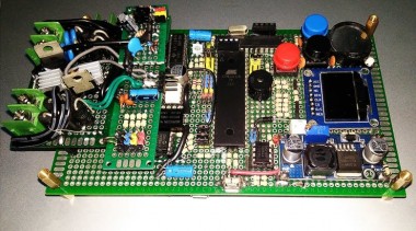
Final Hardware
After building the final hardware :-
 CoolMOS SSP and more....
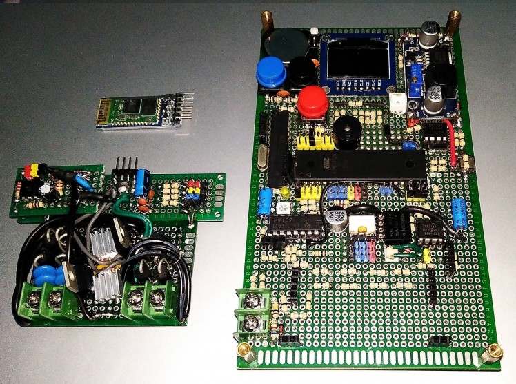 Controller Logic Board, Protected Solid Switch Board & Bluetooth Module
Features
- Source and Load side Protection against Surge & Flyback voltage
- 1500 Vrms minimum Isolation between Control and Power sides
- On board OLED display for monitoring and device configuration
- Multi-purpose design to support Wide Range of Applications
- User Configurable Overload and Short Circuit Protection
- Comparator and Interrupt based Short Circuit Detection
- Soft Start Capability with real Zero Crossing Hardware
- Voltage, Power & Energy Sensing for DC Application
- Current and Frequency Sensing for AC Applications
- Capability to switch both AC/DC loads up to 600V
- RTC for periodic load control and Fault Logging
- OTA/Wireless (Bluetooth) Firmware Upgrading
Application Demonstrations: Single Device, Multiple Solutions
Following are some of the few demonstration how CoolMOS can be used in different applications to serve "not only as a switch but also as a fast protection and fault interrupting device". Events like overload, short circuit, over/under voltage for DC, overload and over/under frequency for AC can be detected with this solution. These protection schemes are user configurable to meet different application scenarios.
Target Application Automotive: Auxiliary System Smart Fuse
Automotive auxiliary system consists of Lighting, Door/Window Control Motors, Window Wiper, Heater etc. These loads may become faulty and create short circuit on the battery power distribution system. Instead of using regular blow fuse to protect car batteries, CoolMOS can be used to implement Smart Fuse.
Smart Fuse for Automotive Auxiliary SystemSmart Fuse restores itself once the fault is cleared. A combination of comparator, current sensor and Interrupt makes the fault detection super fast. As CoolMOS is an automotive grade solution, it is suitable for this purpose.
Target Application Consumer: DC Home Energy Meter & C/B
This device can be used In DC Homes, to keep track of energy consumption and interrupt short circuit events. Therefore, serving as the purpose Energy Metering and (C/B) Circuit Breaker together.
DC Home Supervision Circuit Breaker and MeterFaulty condition like under/over voltage which may be harmful for the DC loads or overload/short circuit which is damaging for the source can be detected with this solution. CoolMOS acts as a safe power switching & fault interrupting device.
Target Application Industrial: Electronic Contactor/SSR
Industrial applications use Magnetic Contactors for switching high power loads. Since CoolMOS has higher Voltage/Current spec, it can easily replace Magnetic Contactors in many applications.
High Voltage AC SSR with ProtectionThis example demonstrates, how CoolMOS based Solid State Relay can switch AC power. The switching is performed at Zero Crossing of 230V. 50 Hz AC, also knows as Soft Switching for which CoolMOS C7 is ideal. The load was 100 Watts incandescent light. Lastly, a short citcuit was emulated by pressing the trip button.
Building the Hardware : Build Log
1 / 2 • Soldering: Hardware Building in Progress Debugging: Testing isolated gate drive signalPutting all the high power semiconductors together :
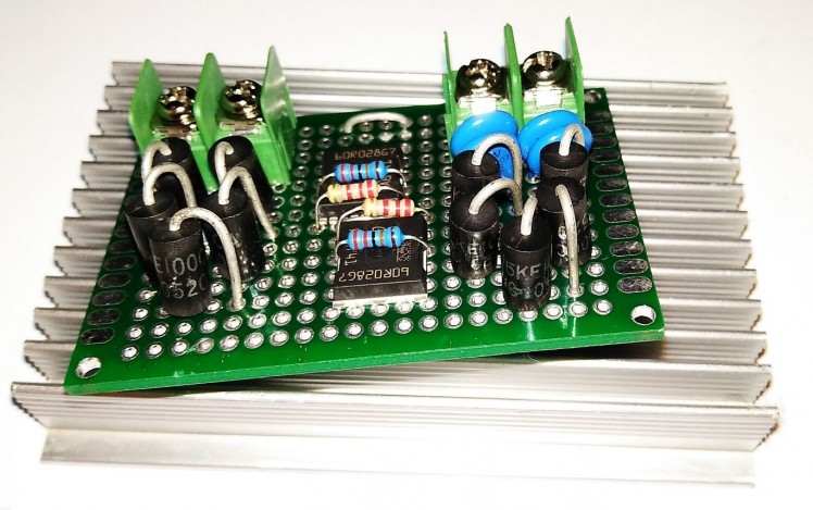 1 / 4 • Bunch of Power Bros ( CoolMOS, TVS and MOVs )
Project development in progress:
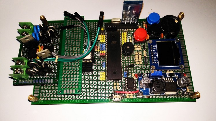 1 / 2 • CoolMOS Solid Switch is connected to the Control Board
Theory of Operation: Hardware Explained
Control, Monitoring and UI
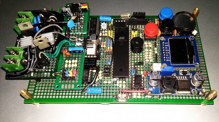
The solution is developed around a custom development proto board which has an Atmega32A microcontroller (MCU) as the system controller. A 128X64 pixel 1306 OLED display for monitoring parameters, 3 push switches for user input and a buzzer for alarm makes the UI section.
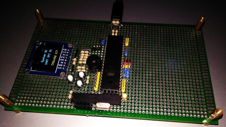 Custom Development Board
It is programmable through Bluetooth<->Serial (or USB<->Serial)modules which interfaces with the on board ISP programmer ( Atmega8A/Atmega328P programmed as Arduino as ISP ). The ISP programmer programs the Atmega32A chip through SPI interface.
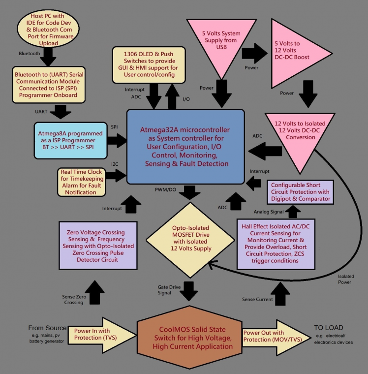 System Block Diagram
Reasons why this custom board is used:
- Enough I/O pins available for design
- Breakout of all mcu pins for breadboard prototyping and verification
- On board soldering space for permanent circuits after verification
- Easy Bluetooth-UART programming with Arduino IDE
Wireless Bluetooth ISP Programming with UART-SPI
One of the painful part of hardware prototyping is that, it requires connecting the development board to PC and program it again & again until a working firmware is ready !
This is where Bluetooth ISP (In Circuit Programming) comes handy. This method requires 2 steps:-
Step 1: Prepare an ISP programmer according to this instruction
- Get a spare Arduino board and connect to PC
- Burn the Example code from Arduino IDE : File > Example > Arduino ISP
- Remove the programmed Atmega328P chip from Arduino board and solder it on the Development Board of this project.
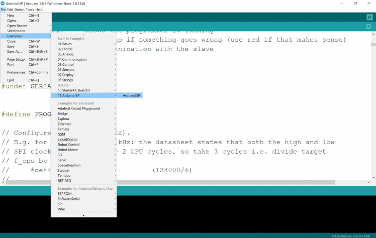 Making an ISP programmer
Step 2: Prepare Bluetooth-UART link according to this instruction
- Get a HC-05 Bluetooth Module
- Connect to PC with a UART module in AT command mode
- Change UART Setting to 19200, 0, 0
AT
AT+UART = 19200,0,0
AT+RESET
- Connect the HC-05 to ISP programmer according to following diagram:-
After completing both steps and putting both the modified HC-05 & Atmega328P*** programmed to act as ISP programmer on the development board according to this circuit diagram, now the development board is ready to code.
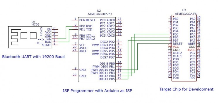 Bluetooth ISP programmer circuit
CoolMOS Bi-Directional AC/DC Configurable Switch
MOSFETs are by default unidirectional switch, in a sense that the other direction will always conduct through body diode inside the MOSFET. So, it won't work as a switch on AC or reversed polarity DC.
But, if Gate pin of one MOSFET is connected to the Gate pin of another MOSFET and Source pin of the first MOSFET is similarly connected to the Source pin of the second MOSFET as following configuration :
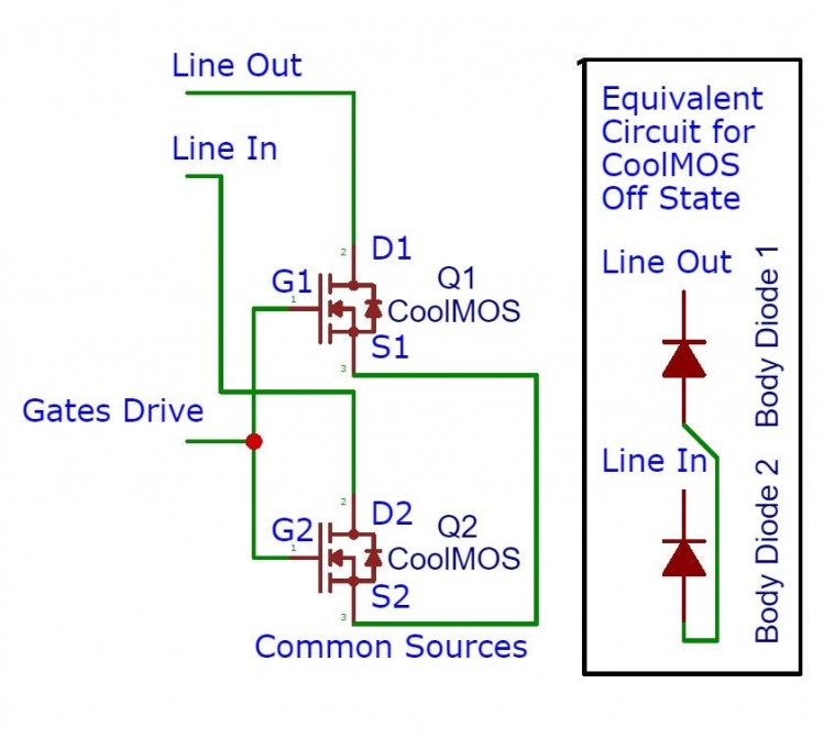 CoolMOS Bi-Directional Solid Switch/Relay
Then, this configuration will be able to switch and block both AC/DC. Since, both the gate pins are tied together, when both MOSFETs are Off, the body diodes inside the MOSFETs will form Back-to-Back configuration, which can block current even for AC/Reverse Polarity DC.
Since, CoolMOS has a high Vds of 650 Volts, this configuration can easily handle standard 110/230 VAC and 5/12/24/48/120/240 DC systems.
When, positive gate drive voltage is applied with respect to source, both MOSFETs will turn on and current will enter through one of the drain pin (coming from supply side) of the first MOSFET and exit through the other drain pin (going to load side) of the second MOSFET. It does not matter which direction this current is flowing, as long as Vgs is above the threshold voltage.
Current Path : Supply <> Drain2 <> Source2 <> Source1 <> Drain1 <> Load
CoolMOS Drive: Opto-Isolated Drive with Isolated Supply
In this project, the control voltage level is 5 volts ( for muc, display, sensors etc) but the controlled voltage may be as high as 600 VDC or 400 VAC.
That's why, every interface between low voltage side and high voltage side must be isolated. If something goes wrong, isolation will prevents high voltage getting into low voltage side as there is no direct conduction path. Isolated sides don't share common ground and prevents interference on Digital circuits from Power circuits.
There are mainly 2 types of isolation :-
- Optical Isolation for signals
- Magnetic Isolation for power
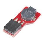
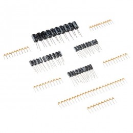
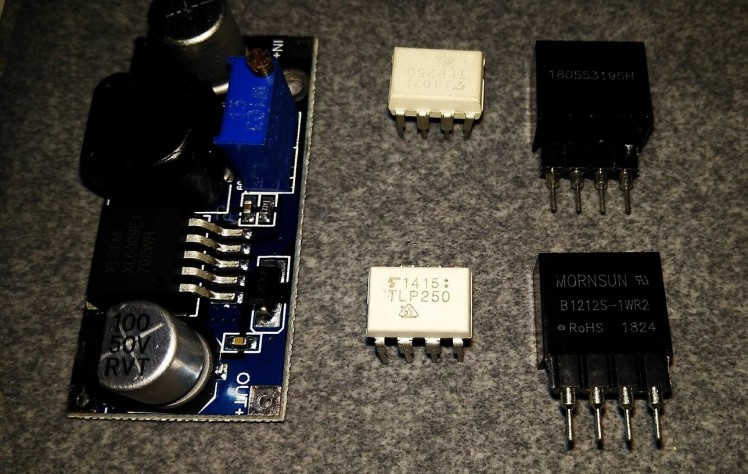 DC-DC boost converter , Opto-Isolator & DC-DC Isolated Converter
To turn on CoolMOS properly, 12 volts Gate to Source voltage should be good enough. But this gate drive voltage must be isolated. To create this voltage, first an XL6009 DC-DC boost converter is used to step up 5 volts to 12 volts. Then, B1212S isolated DC-DC converter is utilized to get isolated 12 volts from 12 volts output of the XL6009.
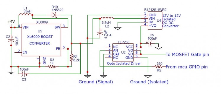 Opto Isolated Gate Drive with Isolated Supply
B1212S-1WR2 has a tiny flyback converter consists of switching element, tiny transformer and rectifier, which turns 12 volts into isolated 12 volts. This kind of isolation is magnetic isolation.
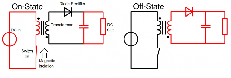 Flyback Isolated DC-DC converter (source: Wikipedia)
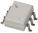
This isolated 12 volts is supplied to power the TLP250 opto isolated gate drive IC. Inside this IC, there is an IR LED which can be turned on/off directly from 1.8/3.3/5.0 volts mcu pin through a current limiting resistor. The IR light will turn on or off the pull-push output drive transistors which will connect the gate drive pin to Isolated 12 Volts or Isolated Ground.
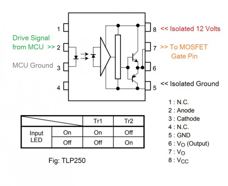 TLP 250 Opto Isolated MOSFET Drive (Source:Datasheet)
CoolMOS Load Side Protection: TVS Snubber against Transient
Most real loads (motors, HVAC, lights etc) are inductive in nature. The problem with inductive load is, when interrupted (turned off), these will create a voltage spike somewhat like this :
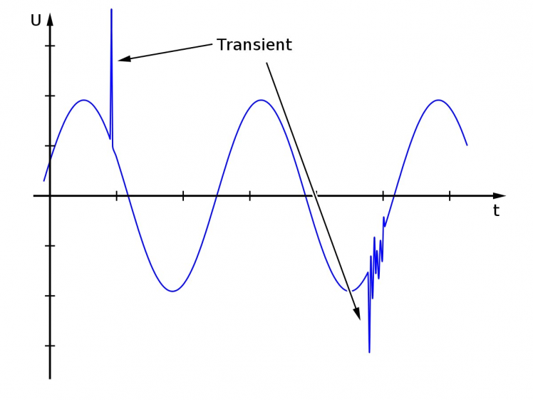 Transient voltage (source:wiki)
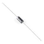
If this voltage exceeds 650V, it will destroy CoolMOS instantly ! Therefore, it is necessary to suppress this voltage spike. One way to suppress this event is to use TVS diodes.
TVS diodes are like zener diodes, except they can handle much larger voltages and power for a short period of time. They act in nano seconds and clamp down the transient voltage spikes.
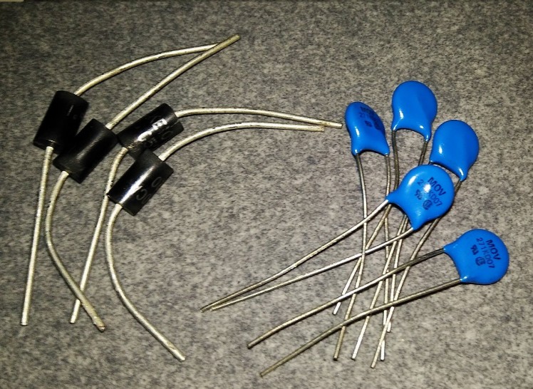 TVS & MOV for transient voltage suppression
For this project, 1.5KE100CA TVS Diode is selected which has a withstand voltage of 85 volts, breakdown starts at 95 volts and clamp up to 135 volts. It's bi-directional, which means it can clamp on AC and reverse polarity DC too.
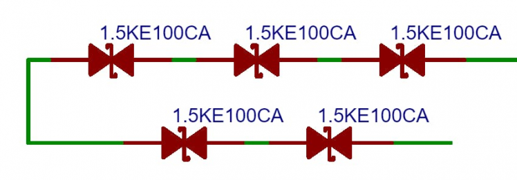 5 TVS Bidirectional diodes in series
A total number of 5 diodes in series is required. Which will give a withstand voltage of
85 x 5 = 435 volts.
Since, AC voltages are represented in rms value (110/230 vac) but the TVS will experience the peak voltage, 5 TVS will start to conduct for any voltage above 310 V (rms) and start to clamp near 350 V (rms) up to 500 V (less than CoolMOS 600V)
Above numbers are calculated using this formula : V(peak) = V(rms) * 1.414
For, 110 VAC systems, 3 TVS diodes should be enough and for 230 VAC, 5 TVS diodes are recommended. Ideal clamp voltage should be less than CoolMOS maximum allowable Vds but 20% higher than nominal supply voltage.
CoolMOS Source Side Protection: MOV against Voltage Surge
MOV or metal oxide varistor is a protection device against voltage surge like TVS diodes with few differences:
- Can usually handle larger transient voltage
- Difference between max allowable voltage and clipping voltage is large
- Degrades over time and eventually fails (short or open)
- Slower in response /cheaper than TVS diodes
- Best for mains input transient protection
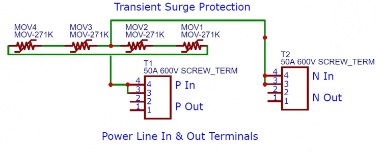 4 MOVs (2 series strings in parallel) on mains incoming protection
MOVs can protect against transient events from lightning, large load swing, power line faults etc. In this project MOV 271K is used which has 175 VAC (rms) maximum allowable voltage with maximum clamping voltage of 455 VDC @ 25A.
Since, this project is intended to be used with both 110/230 VAC systems, 2 MOVs in series is placed and two such strings are paralleled.
It is recommended to use 5 TVS diodes in parallel with this 4 MOVs for amplitude clipping, because 2 MOVs in series has a higher clamping voltage than Vds of coolMOS.
CoolMOS Soft Switching, Zero Crossing Detection & Frequency Sensing
The idea behind Zero Crossing Switching is to -
- Turn On Load when Voltage is crossing zero
- Turn Off Load when Current is crossing zero
This kind of switching is knows as Soft Switching. Soft Switching reduces power loss on switching elements during switching transition because one of the component of power equation ( P = V * I ) is near zero.
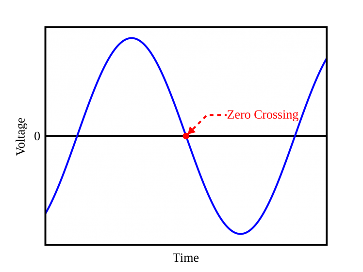 Zero Crossing Point (Source: Wikipedia)
Benefits of using CoolMOS in Soft Switching :
CoolMOS C7's rugged Body Diode are fast enough to handle both Soft Switching and Hard Switching
To perform Soft Switching, microcontroller needs to monitor the Zero Crossing Points on the Supply Voltage and Load Current continuously.
A typical 50/60 Hz mains voltage will have 100/120 zero crossing points per second, which is monitored with following circuit :
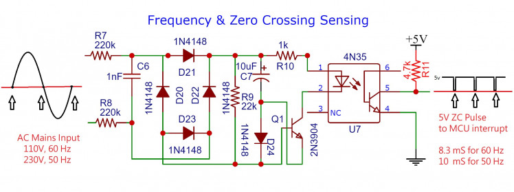 ZVC detection circuit
This circuit will produce pulse train on every zero voltage crossing (ZVC) points and interrupt the mcu to inform the ZVC points.
Two things can be done with this timing information:
- To switch on a load, enable the CoolMOS Gate just at ZVC point
- Measure AC frequency by measuring the time between 2 ZVC pulses
AC Frequency = 1 / (2 x Tbtcp),
where, Tbtcp = Time between two consecutive pulses. Note that, the measured frequency will have some error due to pulse width and mcu execution delay.
Here is the test result of ZVC detector :
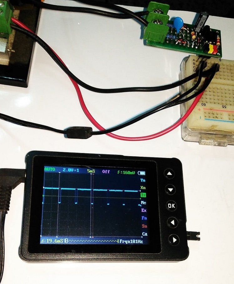 Tested on 230V, 50 Hz mains
Note: During test VAC was 242V and Frequency was 50.5 Hz
CoolMOS Protection against Short-Circuit & Overload with Current Sensing
ACS712/758 series Hall Effect Isolated current sensor is a critical component for this project. This sensor can sense both AC/DC currents and represent the magnitude of the current with an Analog Voltage. When current is zero this Analog voltage is 2.5 volts. If a positive DC current flows through the sensor, this value will increase from 2.5 volts by the amount of mV/A sensitivity and vice versa.
For AC current, the Vout will oscillate above and below 2.5 volts usually like a sine wave.
In this project, ACS712-20A version will be used which has a sensitivity of 100mV/A. Thus, a 5A load current will yield 3.0 Volts (2.5+0.5) output.
Using this current sensor's output, following features can be implemented :
- Instantaneous Short Circuit Protection
- Overload Warning & Shutdown
- Nominal Load Current Monitoring
- Zero Current Switching Tracking
- Power Metering
Short circuit fault must be dealt within micro seconds to protect CoolMOS and other electrical components (e.g. Supply & Load). Using ADC to measure current is too slow for this purpose, because the system MCU might be busy updating display, fetching time data over I2C, measuring frequency etc.
A short circuit event must override everything microcontroller is doing right now and immediately execute gate drive turn off routine, to clear the fault. The fault current setting must be programmable too, which enables this project usable for different types of applications.
Following circuit explains the programmable fault current detection mechanism:
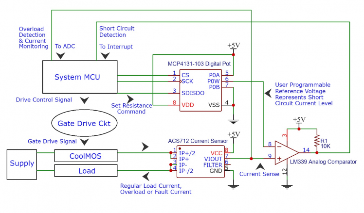 Configurable Short Circuit and Overload Protection with Current Monitoring
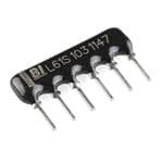
MCP4131 is a 7 bit (127 steps) digital 10k potentiometer (pot) programmable through SPI (Soft SPI) protocol from the system microcontroller. P0A, P0W, P0B pins of this chip are the legs of the 10k pot. P0W is the wiper pin, which sweeps between 0 to 10k with about 80 ohms steps. This sweeping is performed from the microcontroller by sending commands over SPI (in this case Bit Shift Soft SPI).
P0A is connected to 5v and P0B to Gnd, this way P0W pin will output step voltages from 0 to 5000 mV in steps of about 40mV (5000/127 = 39.37). This P0W pin's voltage is the "User Programmable Reference Voltage" which is conneceted to the (-) input of LM339 Comparator.
Now, (+) input of LM339 Comparator is connected to the Vout of ASC712 current sensor.
Let's assume a motor load has nominal full load current of 2A and starting current of 7A which will yield Vout of ACS712 :
2.5 V + 2 A * 100 mV/A = 2.7 V and 2.5 V + 7 A * 100 mV/A = 3.2 V.
The MCU set the MCP4131 P0W pin's resistance such a way that it output 3.5 V. Under normal operation the Comparator will output LOW. If suddenly a Short Circuit occurs, the Vout of ACS712 will spike and make the Comparator go HIGH. Comparator's output is connected to Hardware Interrupt Pin of system microcontroller. This Interrupt will cause the mcu to immediately turn off CoolMOS by disabling Gate Drive Signal. This is how the Short Circuit Protection works.
As, for Overload and Current Monitoring, ACS712 Vout is also connected to the ADC, which will periodically check current for showing on display.
User can configure the Fault Current, Overload Current according to application requirements.
For higher current application ACS758 current sensor is a better choice but the 10 bit ADC of the mcu makes it difficult to monitor small currents with this current sensor.
Following circuit may be used for ZCS purpose. Hysteresis might be necessary for window detection.
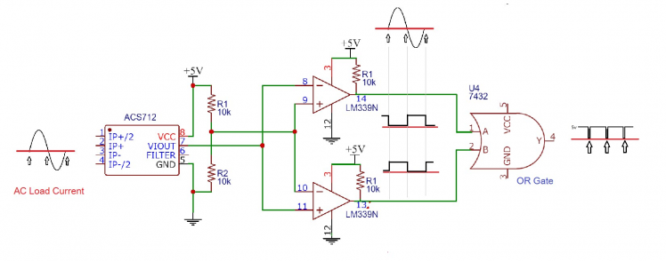 Current Zero Crossing
It detects the current zero crossing by comparing the Vout of ACS712 current sensor against 2.5 Volts. Since, the Vout will swing above and below 2.5 volts for AC load (amplitude depends on load current). During, zero current crossing Vout will be 2.5 when both the comparators will output LOW making the output of the OR gate go low for a brief period of time. This output can be connected to an Interrupt enable input pin of the microcontroller to detect the zero current crossing point and perform ZCS operation.
A note on AC current calculation : AC (rms) current is calculated by detecting the max/min (peak) current with the current sensor and dividing by sqrt(2). This method will work with sinusoidal load currents.
AC RMS Current = Peak Current/ 1.414
System Clock and Alarm
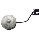
1307 RTC is a timekeeper chip, which can retain date & time information when the whole project is powered down. It only requires a 3V CR2032 Battery to keep going. It communicates with I2C protocol with the system microcontroller.
The purpose of time keeping is to enable following features:
- Timer Load Control
- Periodic Load Control
- Overload Time Duration Monitoring
- Event Logging for Faults
As for alarm, a buzzer unit is connected to one the digital pin of the microcontroller.
It is used to draw user's attention on following events :
- Short Circuit Trip
- Overload Warning
- Timer Alarm
Other Possible Application
With slight modification/addition of few more circuits (also firmware), following application specific solutions can be realized :-
- AC/DC Main Switch
- Automotive Battery Charge Controller
- Overload Limiter and Load Shedding Controller
- Under/Over Frequency Shutdown System
- High Voltage DC Disconnect Switch for Solar
- Programmable Load Controller
- DC Motor Speed Control
- Skip Cycle Power Control for AC
- DC-DC Buck/Boost Converter
- Bluetooth Wireless/IoT Load Control
- Energy Metering
References
- CoolMOS Hard and Soft Switching
- Voltage Surge
- TVS Diode
- MOV Selection Guide
- MOV vs TVS
- Zero Crossing Detector
- Isolated DC-DC Supply
- Opto-Isolated Gate Drive
- Arduino on Atmega32 with SPI
- Arduino ISP
- Bluetooth Sketch Upload
Additional Resources
Arduino IDE (ver 1.0.6)
*** For this Project Atmega8A is used as ISP programmer instead of Atmega328P but circuit connection and ISP firmware is exactly the same.
Disclaimer
WARNING: THIS PROJECT DEALS WITH LETHAL VOLTAGE LEVEL AC/DC APPLICATIONS. THOSE WHO ARE NOT COMFORTABLE WORKING WITH LETHAL VOLTAGE LEVEL, IT IS ADVISED NOT TO REPLICATE THIS PROJECT.
- "Infineon Technologies" logo is the trademark of CoolMOS manufacturer, used to enhance coolness of the project.
- Reference Information used during this project development are added on references section.
- This is a "one size fit all" overkill design with bunch of protection features. For specific applications, certain elements of the circuits may not be required.
Schematics, diagrams and documents
Code
Credits
Related products


Leave your feedback...