
Solar Energy Harvesting Project To Power A Remote Msp430 With 2.4ghz Notification

Made by mbparks / Communication / Sensors
About the project
Solar energy can be harvested on a small scale to provide a self-sustaining energy source for remote installations.
Project info
Difficulty: Difficult
Platforms: Texas Instruments
Estimated time: 2 weeks
License: GNU General Public License, version 3 or later (GPL3+)
Items used in this project
Hardware components


View all
Story
At its simplest, energy harvesting is the ability to take one form of energy and transform it into electricity that can be stored in a battery or supercapacitor (also referred to as a ‘supercap’ or ‘ultracap’). Solar applications range from high voltage roof-top photovoltaics to small solar installations for remote, low power applications. Much attention is given to solar power as an alternative to oil, which is a large-scale application, but solar energy can be harvested on a small scale to provide a self-sustaining energy source for remote installations. The solar panel charges batteries during the day and the remote monitoring unit might transmit a signal or even log the data locally. Energy harvesting devices of all kinds are used to power many low energy applications including mobile device battery chargers, wearable electronics, and remote sensor networks. The MSP430 microcontroller is an ideal remote-use MCU because it is incredibly power-efficient.
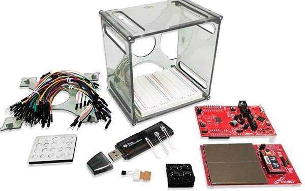
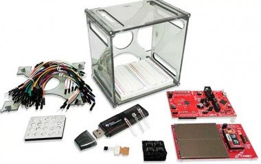
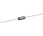
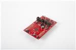
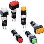
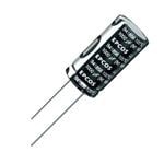
Figure 1:The Bill of Materials in visual form.
To highlight the use of solar energy in a remote application, we are going to use the Texas Instruments (TI) MSP430 microcontroller in a wireless application that you might be tempted to make yourself. Specifically, we are going to test out an Energy Harvesting (EH) platform to power a remote mailbox delivery notification system. The mailbox is used for lack of an actual professional requirement, but the same set-up can be used for remote transmission of a completed action. Once you have a basic grasp of circuit design and programming a microcontroller, you might want to begin explore different microcontroller architectures and platforms to see what's possible. Chip manufacturers sell development boards or kits as a way for engineers to develop and test an application quickly and without the hassle of first building a custom board. Although design engineers use them frequently, makers will find these “dev kits” to be a fantastic opportunity to wade into the deep end of the electronics design pool.
There are many microcontroller platforms in the world, and some may be better suited for certain applications than the venerable Arduino. Here, we present a project using the very popular, extremely low power Texas Instruments (TI) MSP430 microcontroller in an application you might be tempted to make yourself. Here, an Energy Harvesting (EH) solar platform powers a remote notification system.
Project Overview: MSP430 LaunchPad Powered via Solar Panel
Although this set up can be used for any similar remote notification, ours detects when mail is delivered and tells a computer indoors. The computer then drives a servo motor that moves a physical indicator upon status change, when the mail has been delivered.
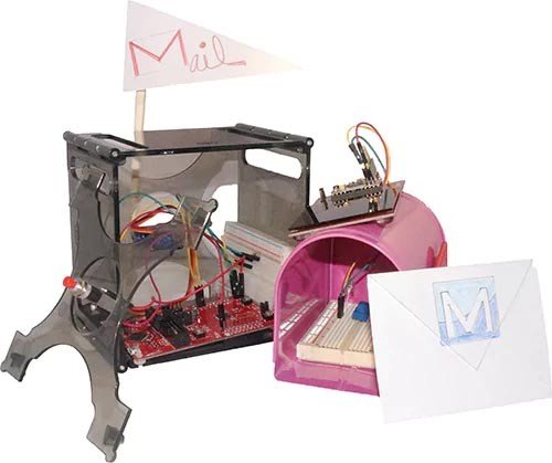
Figure 2: The whole set-up, as wired.
The project consists of two modules: the first is an outdoor solar panel to power the MSP430, an RF transceiver, and a simple ambient light detection circuit mounted inside the mailbox itself. The second module (indoors) is connected to a USB debugger dongle, a computer running a sketch (program), and the MSP430 LaunchPad development board that drives a servo motor to physically move an indicator arm upon status change.
Remote Harvesting (Outdoor) Component
Outdoors, we are using the eZ430-RF2500-SEH Solar Energy Harvesting Development Tool. From the product bulletin, we know the following:
The eZ430-RF2500-SEH Solar Energy Harvesting module includes a high efficiency Cymbet solar panel that can also operate indoors under low-intensity fluorescent lights to provide enough power to run a wireless sensor application with no additional batteries. This kit also has inputs for external energy harvesters and stores additional energy in a pair of Cymbet EnerChip thin-film rechargeable batteries that look like large IC chips.
The eZ430-RF2500 is a kit within a kit; that is, it is included in the eZ430-RF2500-SEH Solar EH kit and is used to run the remote energy harvesting application, which we mount outside with the solar panel. The included eZ430-RF2500 is a complete USB-based wireless development tool itself, and is based around the MSP430 MCU (specifically a member of the MSP430F22x4 family, where the “x” is a number that may vary.) It includes a debugging interface that allows for real-time, in-system debugging and programming for the MSP430 and is also the interface to transfer data to a PC from a wireless system. An external sensor can be integrated to collect additional data, although we don’t use this capability in this project. The eZ430-RF2500 tool kit includes:
- A USB-powered emulator to program and debug an application in-system
- Two 2.4-GHz wireless target boards with MSP430F ultra-low-power MCUs
- A battery expansion board and AAA batteries
- 1 pushbutton
- 2 LEDs
- The eZ430-RF2500T wireless target board
- Integrated TI CC2500 – a 2.4 GHz, ISM band multi-channel low power transceiver
- Removable USB stick enclosure
- Example wireless sensor network project measuring temperature, voltage, and signal strength
- Includes IAR Kickstart and Code Compose Essentials Core Edition, which include an assembler, linker, source-level debugger and limited C-compiler
- Full documentation on CD-ROM
The “–SEH” kit integrates many features that we would have to otherwise design from scratch, including the solar panel, a pair of thin-film rechargeable batteries, protection circuitry, a TI MSP430F2274 MCU, and a CC2500 2.4-GHz wireless transceiver. We will also need to devise a simple voltage divider circuit to use with the ambient light sensor. Since we are simply looking to detect the absence or presence of light inside the mailbox, the voltage divider will suffice. There are more complex circuits that utilize the ambient light sensor as a type of NPN transistor (the base being light sensitive and adjust the emitter to collect current flow) if you wish to have greater resolution, but that’s another topic.
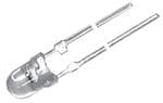
We will use a small 220-ohm resistor in series with a 10k-ohm potentiometer for one half of the voltage divider and the ambient light sensor for the other half. The potentiometer will allow us to manually adjust the sensitivity of the ambient light sensor once it is installed without having to rewrite the firmware if change our location or natural lighting conditions change. One additional alteration we need to make to the ”remote node” MSP430 board (the one outside managing the solar harvesting) is to solder two rows of header pins to make easy access to the microcontroller pins and allow for easy rewiring if we use the boards in a future project.
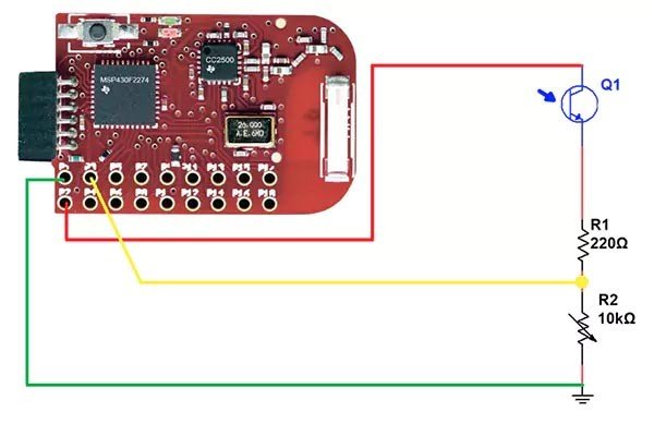
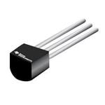
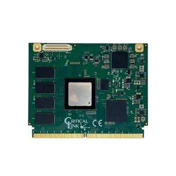
Figure 3: The outdoor mailbox circuit with ambient light sensor with adjustable pot, and the Texas Instruments’ MSP430FR5969.
The solar EH development board provides control circuitry that allows the solar panels to power the MSP430 microcontroller if the sunlight is bright enough. The Cymbet EnerChip batteries in the TI solar kit have extremely low self-discharge rates, making them ideal for EH applications. Once the sunlight drops below an adequate level, the solar panel kit will automatically begin to power the MSP430 from the EnerChip batteries instead. This is an extremely convenient integrated function and will provide enough energy for approximately 400 RF communication bursts before the batteries are depleted. By tweaking the time interval between communication bursts, you can get quite a lot of use out of this board without having adequate sunlight. This is extremely important in many remote-sensing applications.
Programming the MSP430 is fairly straightforward for engineers who have built using other microcontroller platforms. The MCU located indoors, LaunchPad development kit (MSP-EXP430FR5969), comes with a CD containing source code and applications. However, you can ensure that you are installing the latest version of TI’s Integrated Development Environments (IDE) called Code Composer Studio (which was at version 6.0.1 as of this article), and using the latest firmware by but visiting www.ti.com. For others who are coming from a relatively simple IDE such as the official Arduino IDE, don’t let all the features of a more complex IDE overly concern you. The tutorial that comes with the eZ430-RF2500 is well written and will show you everything you need to know in order to make tweaks to the preloaded firmware. To upload new firmware you will use the included USB debugger dongle. Just be sure to remember which MSP430 is the remote node (the one outside with the solar panel) and which one contains the hub firmware (inside, on the LaunchPad kit controlling the servo motor that sets the physical flag.)

Figure 4: No software can run without hardware, so this schematic of the circuit shows the MSP430 LaunchPad with connections to the Servo motor and the switch that resets the physical flag once the mail has been retrieve from outdoors.
We will be making minimal tweaks to the default firmware that comes preloaded on the MSP430 remote node. Specifically, we are tweaking the portion of the code that reads the battery voltage so that it will read the voltage on an external analog input pin, in our case analog pin A0. Recall from the BOM listed earlier that the solar kit comes with the solar panel, an MSP430 MCU (the “remote node”), and two wireless eZ430-RF2500T target boards. The little eZ430-RF2500T boards transmit and receive signals that tell the inside MSP430 setup that the inside of the mailbox has been exposed to light.
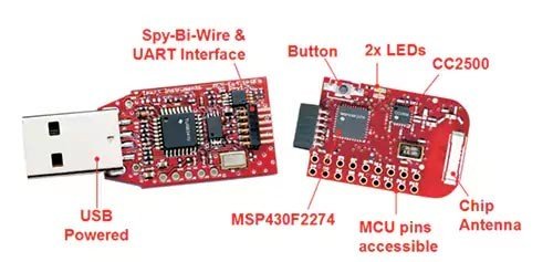
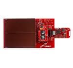
Figure 5: The eZ430-RF USB debugging interface and eZ430-RF2500T wireless target board featuring the CC2500 Low-Power 2.4 GHz RF Transceiver.
The eZ430-RF2500T target board pinout shows that A0 from the MSP430 remote node is brought out to pin 3 on the eZ430-RF2500T target board. This is one of the external pins that we soldered male header pins into earlier for easy access. If you look at the default firmware installed on the remote node MSP430 module we are changing this line of code:
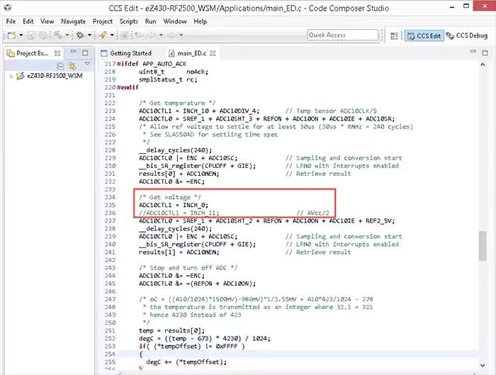
Figure 6: Re-using the demo code that came already installed on the RF2500-SEH MSP430 boards, the above line was tweaked for the remote node firmware using Code Composer Studio. This gets uploaded to the ez430-RF2500T via USB dongle.
After saving the change, we can now upload the new node firmware to the remote MSP430 that’s managing the solar energy harvesting panel (physically located with the panel out by the mailbox) using the USB dongle hardware as a programming tool. Then it’s simply a matter of hooking up the ambient light sensor (as shown in Figure 3) and connecting the MSP430 target board into the EH board (as shown in Figure 4). Remove jumper JP8 and allow the solar panels to begin to charge the board. Verify that the LED onboard the MSP430 remote node blinks when you attach it to the solar panel (Cymbet) board. One thing to note is that if you power the project down and store the EH Cymbet board, be sure to replace jumper J8 before storing the EH board.
At this point if you were going to install this permanently be sure to get a weatherproof enclosure and use heat shrink and a sealant (perhaps something like sugru) to seal the enclosure and keep external wiring tidy. When mounting the device to a mailbox, recall that if you live in the northern hemisphere, it is ideal to face solar panels to the south to maximize sunlight exposure all year round.
Indoor Set-up
The indoor portion of our mail delivery notification system will require the use of a Windows computer. If you can’t spare a computer for a remote project, this whole EH project could be built using just microcontrollers, however using the computer allows you to create new features for this project such as running Python script to send an email upon status change.
The indoor portion consists of the aforementioned Windows computer that will be running a Processing sketch that will interface with two devices external to the computer:
- The inside MSP430 that is running the hub firmware and attaches to the computer with the USB debugger hardware “dongle.”
- The TI LaunchPad Experimenter Development board that controls the servo motor to raise a physical flag inside the house.
We are going to use the open source Processing tools to develop our desktop application in a program called a “sketch.” I choose Processing because when you are in the prototyping phase, there are few development environments that make handling serial communications and creating a basic user interface (UI) as easy as Processing.
To summarize the indoor hardware set up in more detail, the MSP430 module that runs the hub firmware attaches to the computer with the USB debugger hardware dongle. The debugger will show up as a COM port on your computer. Make note of which COM port, as we will use that information in the Processing sketch later.
The other piece of hardware that will connect to the computer is the TI LaunchPad Experimenter Development board. This will enable us to interface with a servo motor that will raise a flag to let the user know that the mail has been delivered. We will also attach a button to allow the user to reset the system (and lower the flag via the servo) after they have gone out and retrieved the mail. As with all digital I/O, don’t forget to include a pull-up or pull-down resistor to prevent a floating input that can make your application unreliable at best and downright faulty at worst.
The pseudocode for our Processing sketch follows:
- Read the serial data packet coming in from the COM port connected to the eZ430-RF2500T board, which is connected to the USB debugger.
- Parse the data packet to ignore the hub data packet and listen only for the remote node data packet.
- Parse the remote node data packet to look for the voltage reading from the ADC.
- If the voltage read is less than 4.5V, assume mail is being delivered.
- Send serial data packet to the LaunchPad letting it know mail was delivered and to raise the flag.
The LaunchPad that controls the servo will be programmed using the Energia IDE instead of the Code Composer Studio that was used earlier. This IDE looks quite similar to the Processing IDE and should make transitioning between the two very easy, and troubleshooting any communication bugs much easier. The firmware will wait until a specific keyword is received from the computer; in this case the flag will be a string with the value “MAIL”. Once it receives the keyword it will then turn the servo 90 degrees, raising the flag. We can use a servo library provided on the Energia website which will make driving the servo much simpler by abstracting the code required to do pulse width modulation duty cycle calculations; it reduces the servo interaction to a simple function call for us. In addition, we need a function to handle the reset button connected to one of the LaunchPad digital I/O pins. In this case the function will drive the servo to lower the flag and allow the system to once again listen for the “MAIL” flag coming in on the serial port.
Conclusion
There are a great number of microcontroller platforms (and software tools) out there and using a Texas Instrument LaunchPad development board is a great way to get started. The MSP430 has extraordinarily low power requirements and is ideal for energy harvesting applications where power efficiency is key. Whether you are a seasoned engineer or a weekend warrior maker, learning different platforms is an incredibly valuable skill. Exposure to a variety of platforms allows more flexibility when thinking through all possible solutions for solving specific problems. Here, we laid out one possible solution for a remote mail delivery notification system using the TI MSP430 microcontroller. How would you modify it to suit your needs, or would you repurpose the design for a completely different application?
Credits
mbparks
Mike Parks is the owner of Green Shoe Garage, a custom electronics design studio and security research lab located in Southern Maryland. He produces content for the Gears of Resistance which shares news and tips for those interested in the maker movement, open-source hardware and software, STEAM education, citizen science, and digital citizenship. He is also an extra class ham radio operator, a licensed Professional Engineer in the state of Maryland, and most notably a dad.
Related products


Leave your feedback...